Table of Contents
This is an old revision of the document!

EVO: Engine Mechanicals
Camshafts

Removing / Installing Evo Cams
Sub-Documents
- . . . Installing Evo Cams
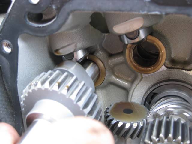
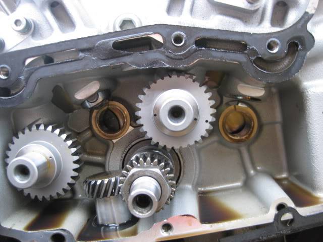
Positioning the Pinion Gear
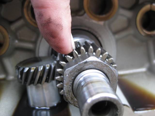
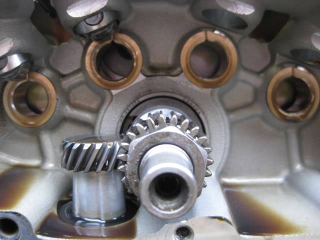
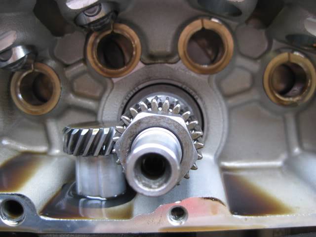
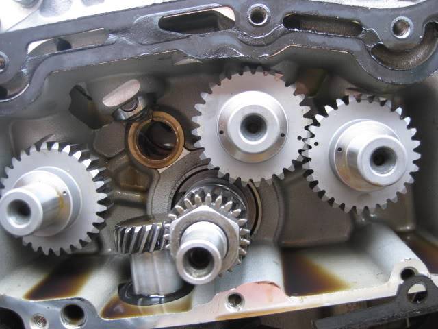
| The pinion gear has a notch on one of the teeth. Rotate the notch to point towards the center of the #2 cam hole. 1) | It may not be easy to get it to settle straight on. At this location, the piston is rising to about 3 teeth before TDC (exhaust stroke). It's too far right in the this pic. 2) | And too far left in this one. While rolling the engine backward to align the mark, the weight of the rod / piston adds a small amount of motion force to a small turn of the wrench or rear tire. 3) |
 |  |  |
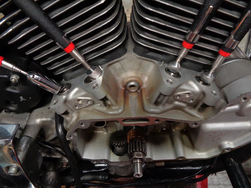
Working Around the Lifters If Installed
- Obviously, it's easier to have the lifters removed and out of the way when installing cams.
However, it's not an real issue with the lifters installed. They will probably have to be raised up slightly so the cam lobes clear them on installation. Just make sure the lifters have been primed with oil before buttoning up the cam chest. - There is only a very small clearance between the camshaft and the bushing.
If there is any binding, do not force the cam in. The steel shafts can damage the brass bushings. Pull it back out and try again. - Lube the cam journals and bores before installing them.
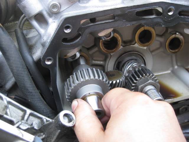
| Bring each cam up it's bushing and align it straight before attempting to slide it in. | The lifter hangs down below the cam lobe camshaft lobe 4) | A telescoping magnet can be useful to hold them out of the way 5) |
 |  |  |
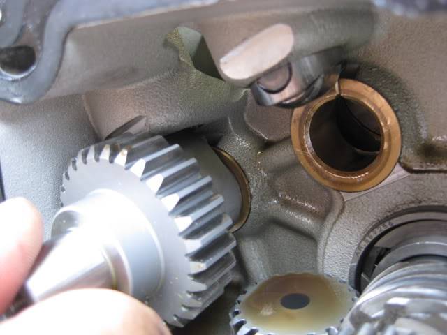
Or, the lifter can be bumped a little while the cam is on it's base circle as in below.
| Roll the cam around to it's base (small) circle end, slip the shaft under the lifter and turn the dot where it needs to be 6) | ||
 |  |  |
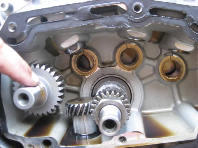
Timing The Cams
- Install each cam in it's respective bushing (1-4 from back to front).

- #1 and #3 cams should go in first. The order of these two are unimportant as long as the dots are aligned properly.
- Caution: Double check the numbers on #1 and #4 cams before installing them.
These two look alike and are the only ones that have 1 dot each.
Switching them can result in engine damage from the valves opening / closing out of sync.
| #1 cam dot faces the center of the #2 cam bore | #3 has two dots. Each dot faces toward the center of the two adjacent cam bores (#2 and #4 respectively). The dots won't line up correctly installed upside down. |
 |  |
- #4 cam can be installed at any time after #3 is in place and it's the least of the worries of installing incorrectly (outside of checking that the cam number is correct).
- #2 cam has two separate gears on the same shaft and three alignment dots.
The smaller gear behind meshes with both #1 and #3 while the bigger outside gear meshes with the pinion gear.
(The outside gear drives all of the cams with help from the pinion gear).- It is also the most difficult one to install.
With all three dots seemingly aligned properly, you'll probably still have to massage any one of the adjacent gears to get #2 to slide in.
Be patient and don't force it or scarring of the bushing can occur. - Match up the pinion gear mark and the middle cam dot first. Then massage or move cams 1 or 3 to mash up in alignment.
You'll have to pull #2 out (just out of mesh in order to move the others.
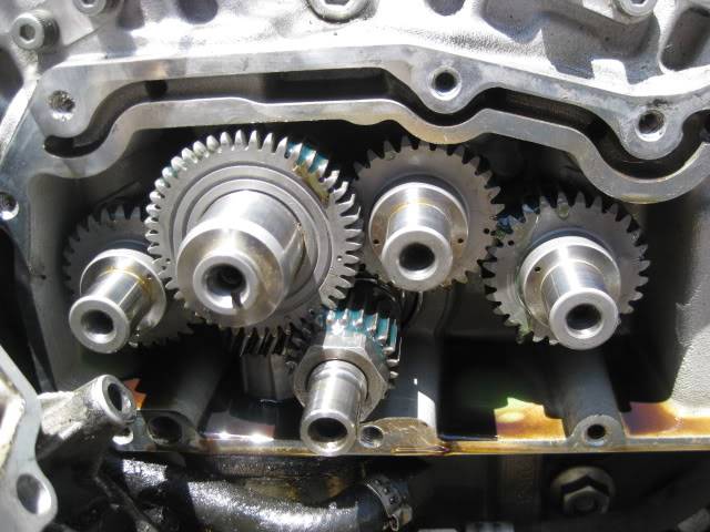
| #4 cam dot faces the dot on #3 | #2 cam dots line up with 1,3 and the pinion gear mark. This is how it should look when done |
 | 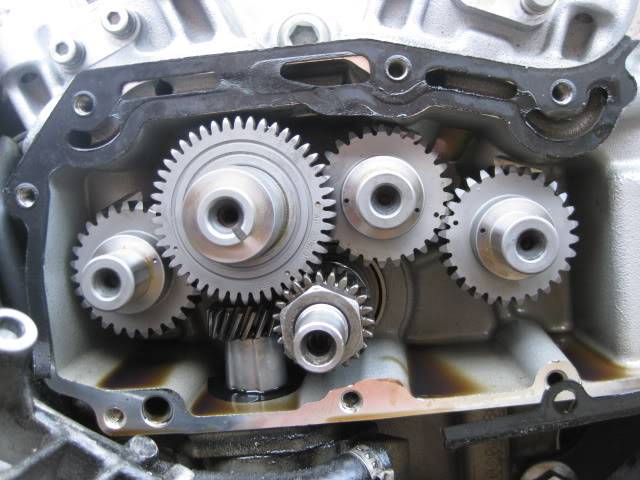 |
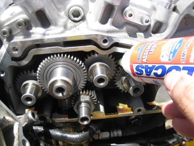
Before Installing the Cam Cover
| Lube the cover bushings and the cam gears and shafts. 8) | |
 |  |
Verifying TDC by Cam / Timing Cup Positions
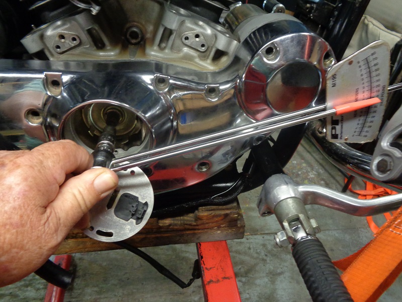
- While positioning the piston to TDC, the general rule of thumb is to place your finger in the spark plug hole and wait for pressure to be forced out past your finger to verify you're on the compression stroke.
- An extra visual (when you've got the piston to TDC) is to check the position of the slot in the #2 cam or the timing cup (assumed that they are installed and done correctly).
Click on a pic to enlarge:
- With the gearcase cover off: The #2 cam slot will face up and to the left on compression stroke and down towards the right on exhaust stroke.


- With the gearcase cover on, ignition module removed: The slot in the timing cup sits inside the slot in the #2 cam so the positioning is the same respectively.


Pinion Gear
Compatibility 13)
Frame mount Evos 1986-2003 do not list a part number for the pinion gear and it appears the pinion gear is part of the (cam gear set).
| Pinion Gear Part# | Year Models |
| 24047-00 | 2004-2016 All Models |
XL Pinion Gear Color/Size Info here: http://xlforum.net/forums/showthread.php?t=1963918
Timing Cup (Rotor)
Cam Bushings
- The cam bushings get their oil from the fling off of the cam gears and drain back from the top end down the pushrod tubes that puddles in at depressions in the castings where the cam bushing slots are aligned. So basically they are drip fed. Also the cam bushings on the case side are open to the crank behind them, and probably get splash there too. 17)
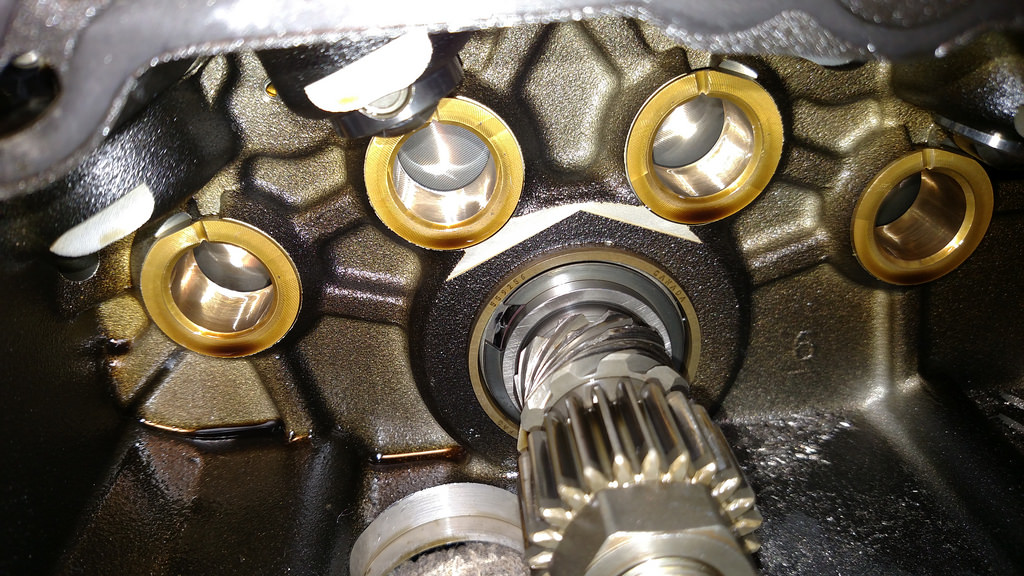 | 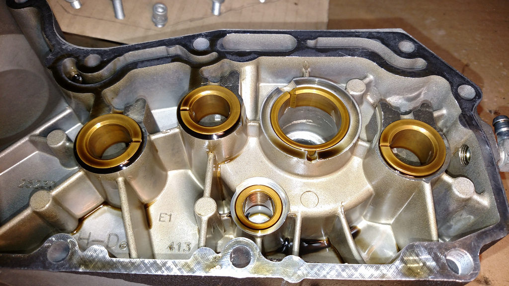 |
| 2010 1200X Inner Cam Bushings (broken teeth on oil pump gear) 18) | 2010 1200X Cam Cover and Bushings 19) |
1)
, 2)
, 3)
, 4)
photo by Phillober of the XLFORUM http://xlforum.net/forums/showthread.php?t=1122547&page=6
6)
photos by Phillober of the XLFORUM http://xlforum.net/forums/showthread.php?t=1122547&page=6
7)
photo by Phillober, annotated by Hippysmack of the XLFORUM http://xlforum.net/forums/showthread.php?t=1122547&page=6
8)
photos by Phillober of the XLFORUM http://xlforum.net/forums/showthread.php?t=1122547&page=7
11)
photos by Hippysmack
13)
From HD Parts Catalogs 2004 pg 17, 2005 pg 19, 2006 pg 19, 2007 pg 19, 2008 pg 19, 2009 pg 25-27, 2010 pg 25-27, 2011 pg 25-27, 2012 pg 25-27, 2013 pg 29-31, 2014 pg 17, 2015 pg 19, 2016 pg 19
18)
photo by lostNdallas of the XLFORUM http://xlforum.net/forums/showthread.php?t=1974986&highlight=bronze+drive+gear&page=6
19)
photo by lostNdallas of the XLFORUM http://xlforum.net/forums/showthread.php?t=1974986&highlight=bronze+drive+gear&page=4