Table of Contents
This is an old revision of the document!

EVO: Engine Mechanicals - Sub-02A
Installing Evo Cams (91 and Up)
Positioning the Pinion Gear
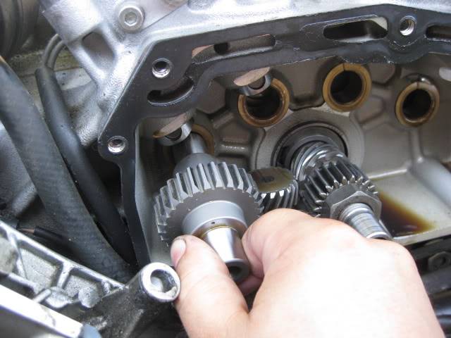
- To rotate the engine to correctly position the pinion gear, either:
- Put the transmission in 5th gear with the (rear wheel of the ground) and turn the wheel forward.
The wheel will still offer some resistance with the plugs in so take them out also. - Or (with the primary cover off), use a wrench on the engine sprocket nut
(with the transmission in neutral AND the spark plugs removed). - Or (with the cam cover off), use a 15/16“ wrench on the pinion gear nut
(only with the transmission in neutral AND the spark plugs removed).
Turning the pinion side against compression and tranny gearing can result in mis-aligned flywheels.
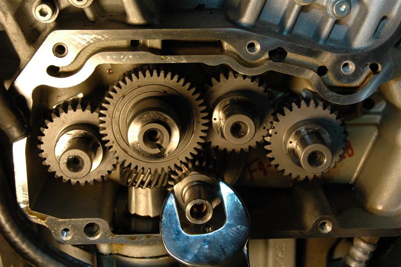
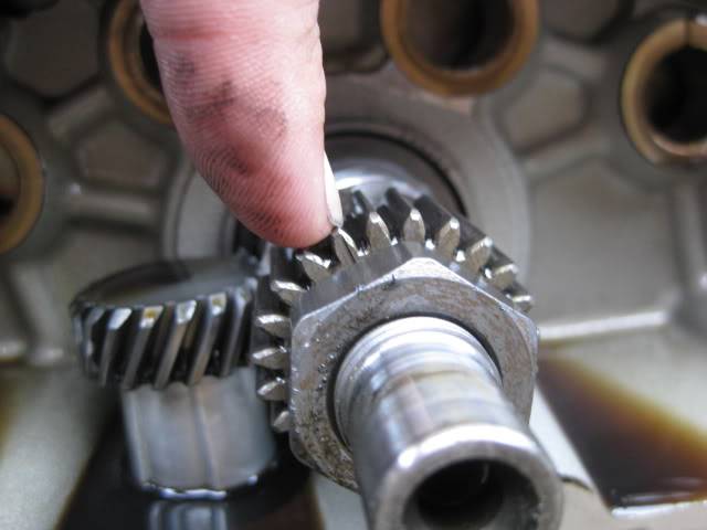
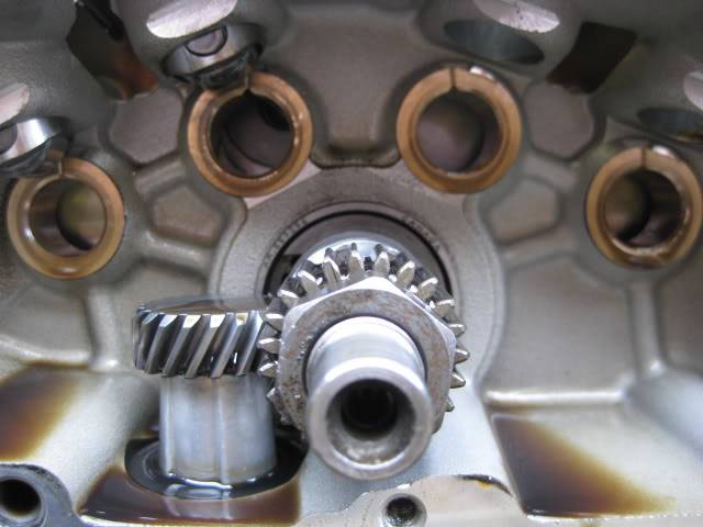
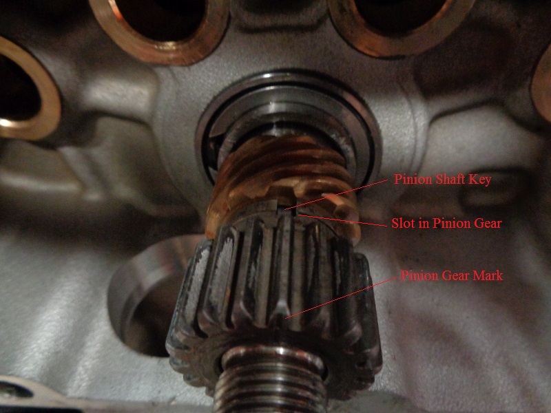
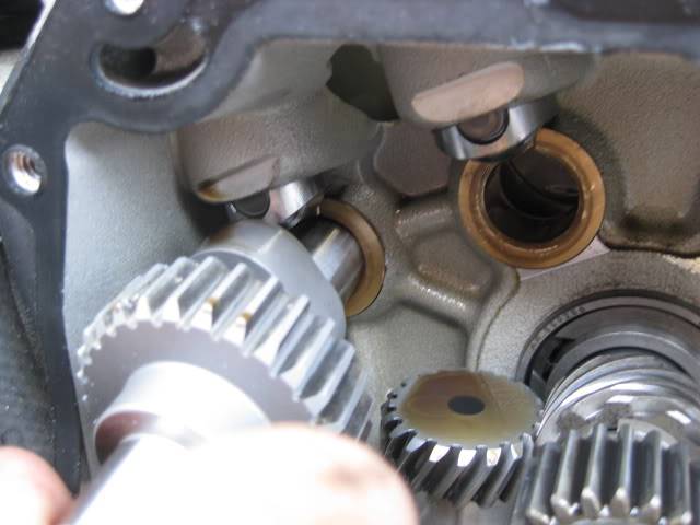
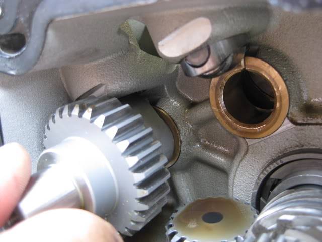
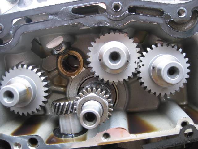
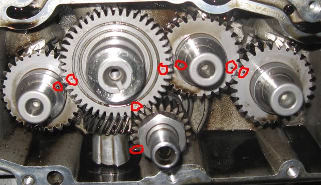
| The pinion gear has a notch on one of the teeth. Rotate the notch to point towards the center of the #2 cam hole. 2) | It may not be easy to get it to settle straight on. At this location, the piston is rising to about 3 teeth before TDC (exhaust stroke). It's too far right in the this pic. 3) | And too far left in this one. While rolling the engine backward to align the mark, the weight of the rod / piston adds a small amount of motion force to a small turn of the wrench or rear tire. 4) |
 |  |  |
Inspect the Pinion Gear Mark and Keyway Slot
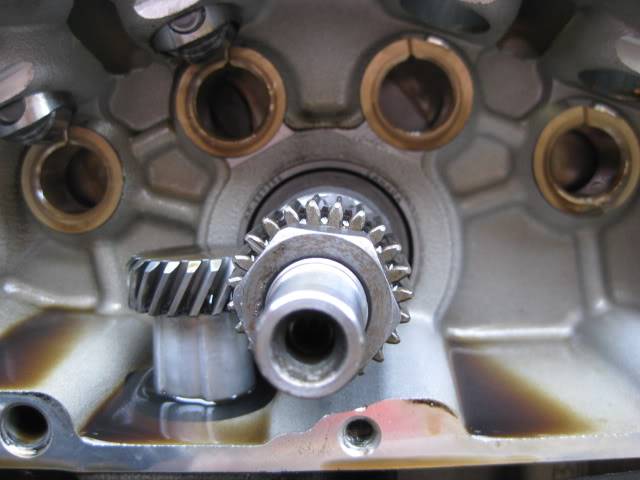
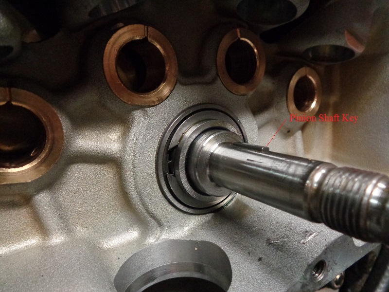
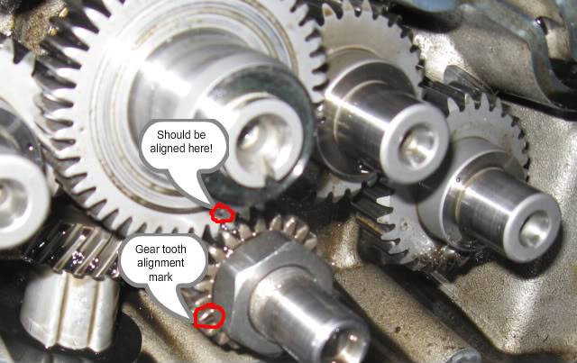
To be sure where the mark should be on the pinion gear, look at the keyway on the shaft. The key and the correct tooth should be in line with each other. 5)
The mark on the gear is a visual aid only and it represents the position of the pinion shaft.
So, it can also be said that the keyway on the pinion shaft should line up with the center of #2 cam.
Installing the Cams
Checklist
- Read the Service Manual prior to performing any work! 8)
- Make sure the cams are clean and free of debris prior to installation (brake cleaner works well for this).
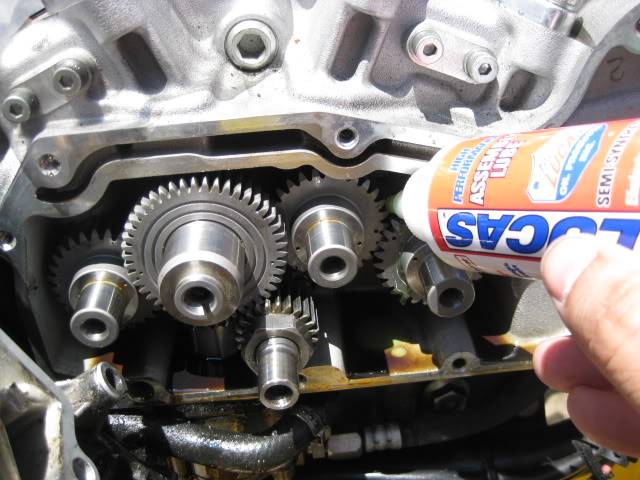
- Lube the cam journals and bores before installing them.
You can wait until the cams are in place to lube the gears but this needs to be done as well to help lube them until oil pressure can get to them. - Install each cam in it's respective bushing (1-4 from back to front).
- There is only a very small clearance between the camshaft and the bushing.
If there is any binding, do not force the cam in. The steel shaft can damage the brass bushing. Pull it back out and try again.
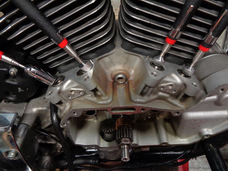
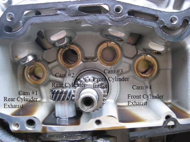 Cam hole identification in the gearcase: 9)
Cam Timing Mark Identification
Note: If your cams have “V” markings on them, disregard those markings. The “V” markings on the cams are not used for timing Sportsters. 10) 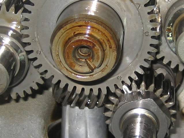 11)
11)  12)
12)
Here's a Buell XB using the 'V' timing marks on the cams. 13)
Working Around the Lifters If Installed
- Obviously, it's easier to have the lifters removed and out of the way when installing cams.
However, it's not a real issue with the lifters installed. They will probably have to be raised up slightly so the cam lobes clear them on installation. - Just make sure the lifters have been primed and pumped up with oil before buttoning up the cam chest.
| It is common practice to leave them soaking in clean oil (same as you'll be using) while removed. | |
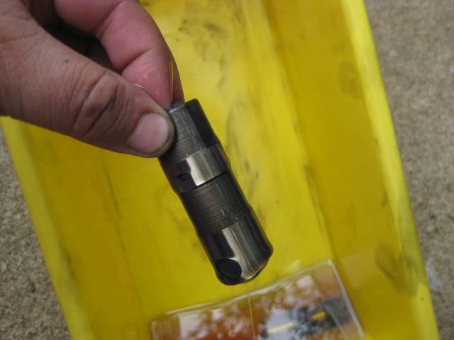 |  |
| Bring each cam up to it's bushing and align it straight before attempting to slide it in. | The lifter hangs down below the cam lobe camshaft lobe 14) | A telescoping magnet can be useful to hold them out of the way 15) |
 |  |  |
Or, the lifter can be bumped a little while the cam is on it's base circle as in below.
| Roll the cam around to it's base (small) circle end, slip the shaft under the lifter and turn the dot where it needs to be 16) | ||
 |  |  |
Timing The Cams
Piston Position (TDC) Has Nothing To Do With Cam Installation or Timing
The mark on the pinion gear has to be pointing to the center of the #2 cam.
That's all there is to it. It's not any more complicated than that.
If you turn the crank to where the mark is pointing to the center of the #2 cam, the piston position is decided for you.
You can't move the mark on the pinion gear independently of the piston position.
They are mechanically connected (pinion gear-crankshaft-connecting rods-pistons). 17)
Exactly where the piston is positioned when you've got the pinion mark pointing to the center of the #2 cam is totally irrelevant.
It happens to not be TDC on either cylinder.
But the piston position is not your reference point, the mark on the pinion gear is your reference point. 18)
The cam markings are defined as (in the middle of a cycle) not at TDC.
They were factory marked to be installed as such making them properly aligned relative to the whole engine rotation.
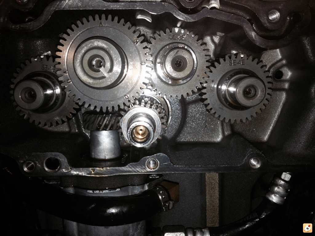
All four cams are installed as described in the service manual and as illustrated below without rotating the cylinders.
Then when the engine is rotated to TDC, the valves will be opened and closed at the right time.
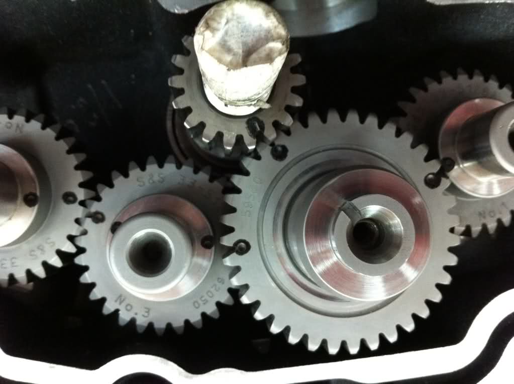
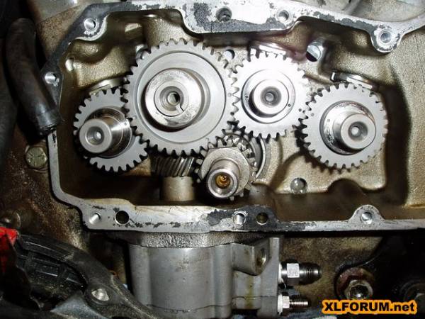
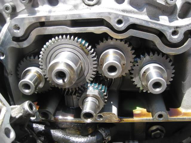
All cams are mechanically aligned based on the placement as in the pictures below. 19)
All you have to do is line up the dots on the gears. 20)
Checklist
- Caution:
The dots on the cams correspond to the cam lobe positioning in relation to the crankshaft, pistons and valves.
Cam lobes open / close the valves at the proper 'time' and in relation to the rise and fall of the pistons.
All dots must line up properly.
Incorrect cam timing can result in engine damage from the valves opening / closing out of sync.
Some damage pics from this can be seen below.
- Double Check the numbers on #1 and #4 cams before installing them.
These two look alike from the front and are the only ones that have 1 dot each. - The notch on the pinion gear tooth can be difficult to make out. It's just a small slot cut long-ways on one tooth face.
You may need to clean the pinion gear teeth enough to be able to clearly tell the difference.
See pics of the pinion mark by itself above.
Cam Placement and Arrangement
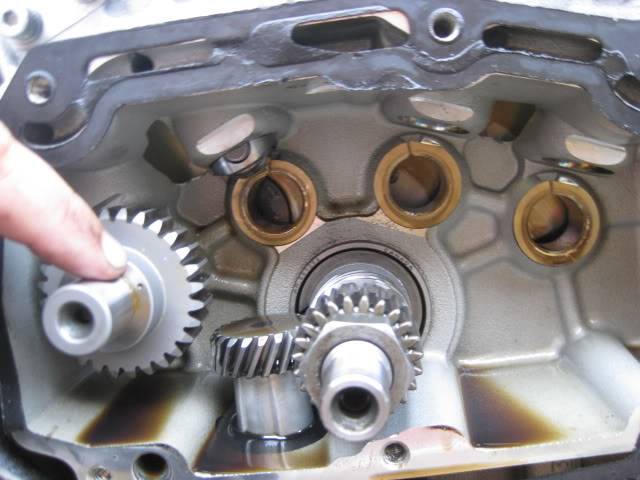
- #1 and #3 cams should go in first. The order of these two are unimportant as long as the dots are aligned properly.
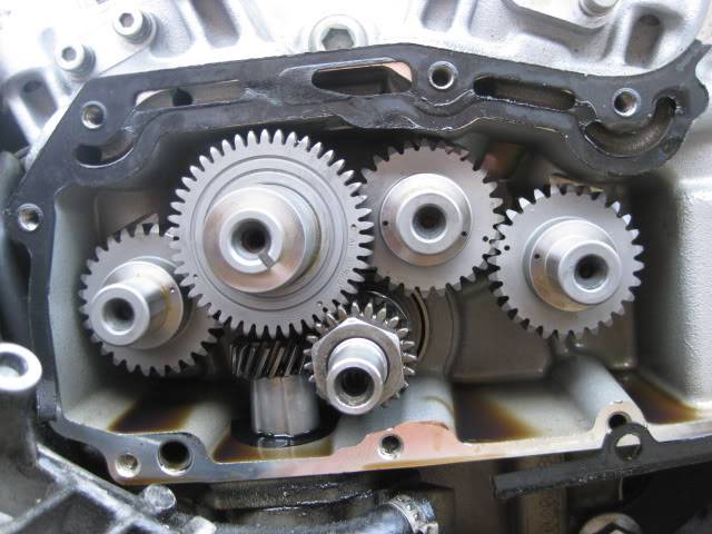
| #1 cam dot faces the center of the #2 cam bore | #3 has two dots. Each dot faces toward the center of the two adjacent cam bores (#2 and #4 respectively). The dots won't line up correctly installed upside down. |
 |  |
| 86-90 cam alignment 21) |
 |
- #4 cam can be installed at any time after #3 is in place and it's the least of the worries of installing incorrectly (outside of checking that the cam number is correct).
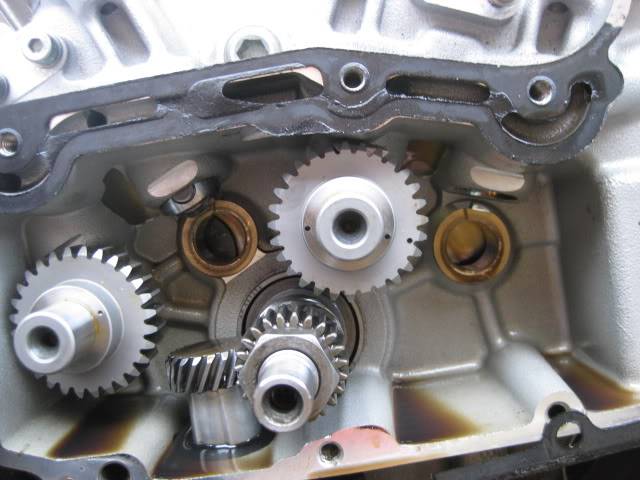
- #2 cam has two separate gears on the same shaft and three alignment dots.
The smaller gear behind meshes with both #1 and #3 while the bigger outside gear meshes with the pinion gear.
(The outside gear drives all of the cams with help from the pinion gear).- It is also the most difficult one to install.
With all three dots seemingly aligned properly, you'll probably still have to massage any one of the adjacent gears to get #2 to slide in.
Be patient and don't force it or scarring of the bushing can occur. - Match up the pinion gear mark and the middle cam dot first. Then massage or move cams 1 or 3 to mash up in alignment.
You'll have to pull #2 out (just out of mesh in order to move the others.
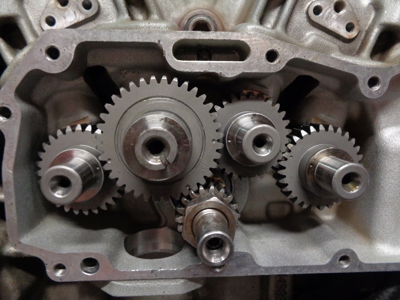
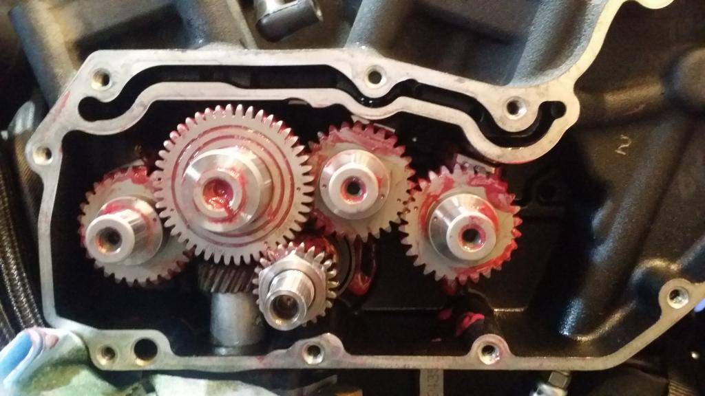
| #4 cam dot faces the dot on #3 | #2 cam dots line up with 1,3 and the pinion gear mark. This is how it should look when done |
 |  |
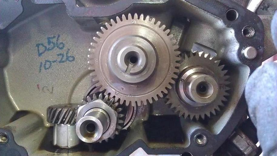
The Exact Position of the Timing Marks May Have To Be Interpreted
- Sometimes, the cam marks leave room for interpretation as in don't quite line up dead bang.
The root cause of the problem is the clearance between the camshafts and their respective bushings.
Without the cover in place, the cams hang down some.
Some hang down more than others because they have less support.
It's particularly bad on the #1 cam, as pictured, because the #1 cam sags down and the #2 cam doesn't (it's supported by the pinion gear).
And, you're relying on a mark on the #1 cam that's not directly on the teeth. 22)
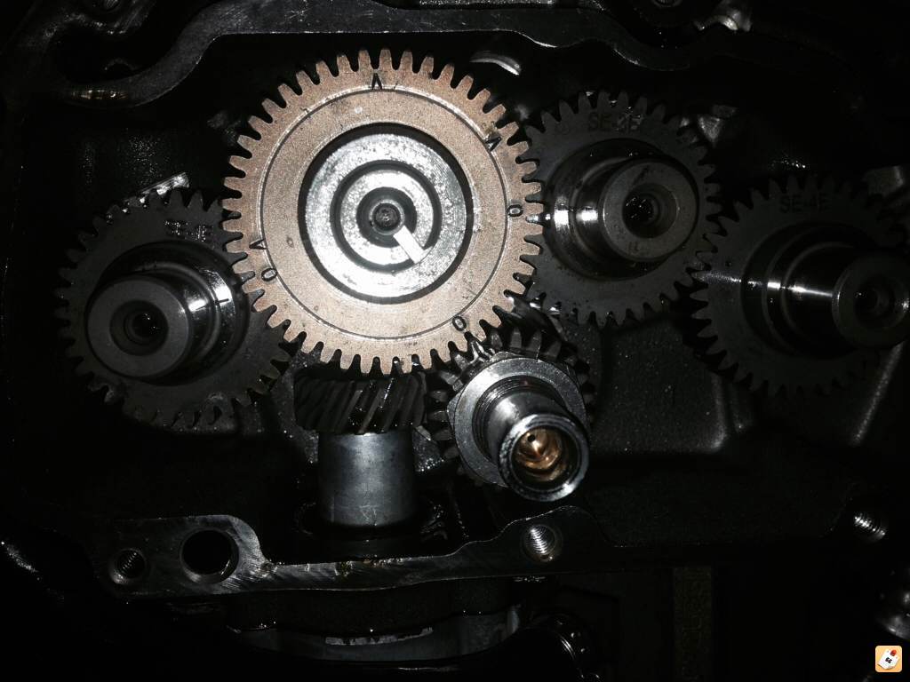
- With #2 being in a fixed location against the pinion gear and #1 cam sagging a bit, the gears between the two stay in mesh.
But, due to gravity and the cams not being supported by the cover just yet, #1 cam can 'roll' or sag slightly in it's bore.
This makes it look off center with #2 cam centerline. 25) - In reality, you have two gear connections that are plainly visible and really leave no room for interpretation: 26)
- Pinion gear to Cam #2.
- Cam #3 to cam #4.
- The gear connections you're concerned about are the ones you can't see (behind #2 outside gear):
- Cam #2 to cam #1.
- Cam #2 to cam #3.
Before Installing the Cam Cover
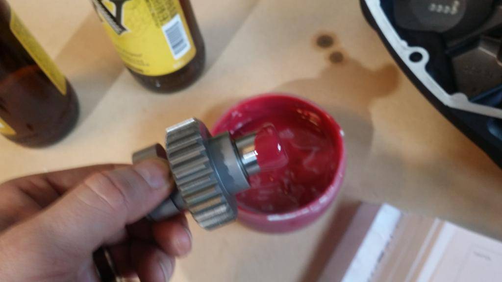
| Lube the cover bushings and the cam gears and shafts. 27) | |
 |  |
| Some like more than others but the more lube, the better. Just be sure not to put thick lube in the pinion shaft hole and block the oil path. 28) |
|
 |  |
Damage Pics From Incorrect Cam Timing
Some useful links on cam installation
- Installing XL Cams from Hammer Performance. AKA, more than you ever wanted to know about installing cams in an XL. (aswracing)
- XL Camshaft Installation from NRHS Performance