Table of Contents
This is an old revision of the document!

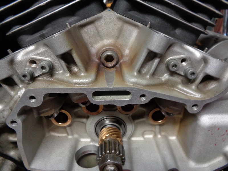
EVO: Engine Mechanicals - Sub-02B
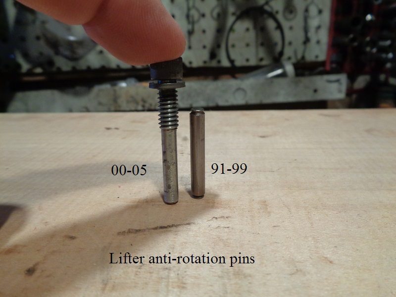
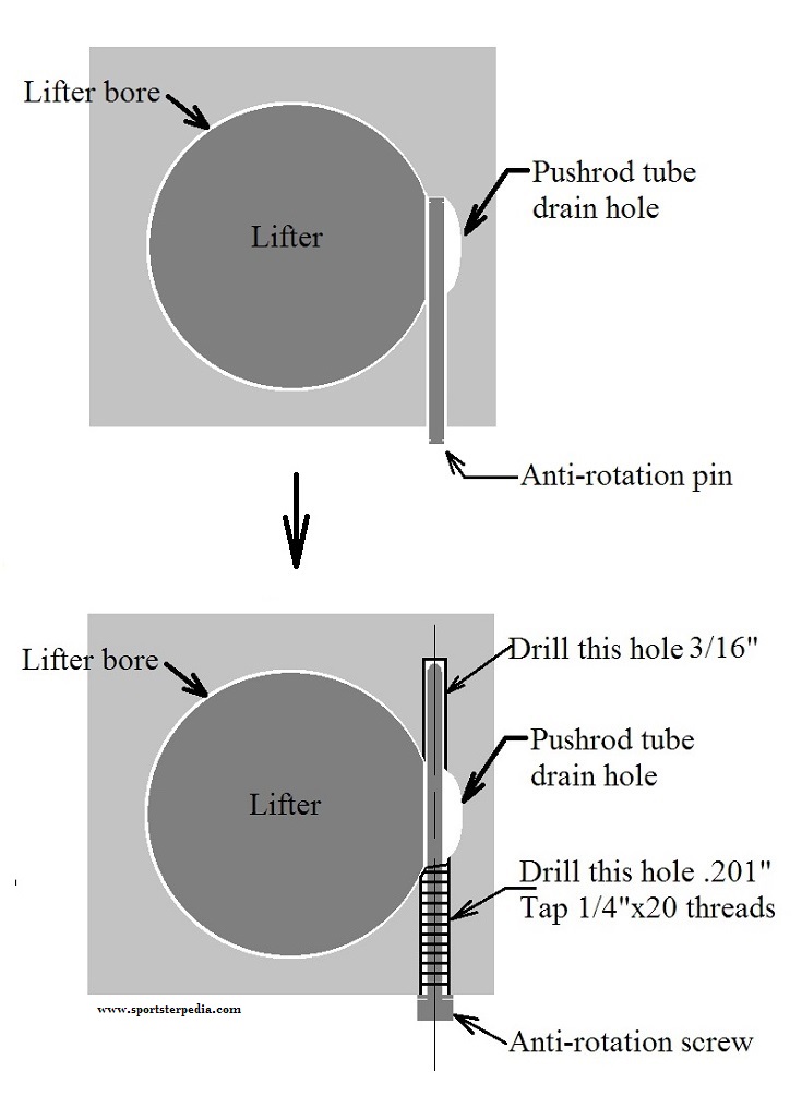
91-99 Lifter Pin Upgrade to 00-05 Lifter Pin Screws
The stock pin on 91-99 engines is supported only on the outboard side of the lifter bore only. 1) 2)
Therefore, it doesn't have a lot of strength or stability (particularly with inadequate clearance).
And it doesn't take much contact (from the lifter) to cause a failure.
By drilling the hole deeper and using a longer pin, you gain support for the pin on both sides of the lifter bore, inboard and outboard.
Zipper's has a long pin kit that came out in the 90's.
It is an alternative to tapping for the threaded pins. 3)
That retains the stock look with the triangular cover.
You can also have longer pins made at your local machine shop.
But you still have to drill the hole longer for the extra length pins.
But then HD one-upped them in 2000 when they came out with the screw-in pins (18532-00) as shown below. 4)
Not only is it longer to provide better support like the Zippers solution, but the outboard side is positively locked in place via the threads.
The main thing with installing either style upgrade is to drill the hole straight. If you're off even slightly, the tappet pin may try to bind the lifter. 5)
It can be done with a hand drill on an assembled motor if you're careful, but it's best done in a drill press or a mill with the right case half removed.
Basically you just punch the hole deeper with a 3/16“ drill bit, drill the outer portion only with a .201” bit and tap it to 1/4-20“ threads.
Put tape on each drill bit so you know where to stop.
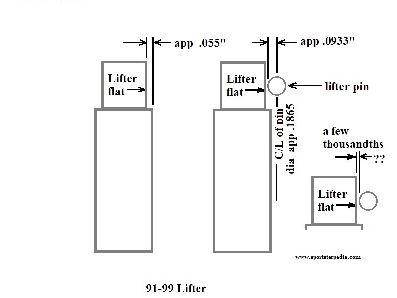
Anti-roll pins are designed to keep roller lifters from turning sideways during operation.
A roller that's turned sideways does not roll. 6)
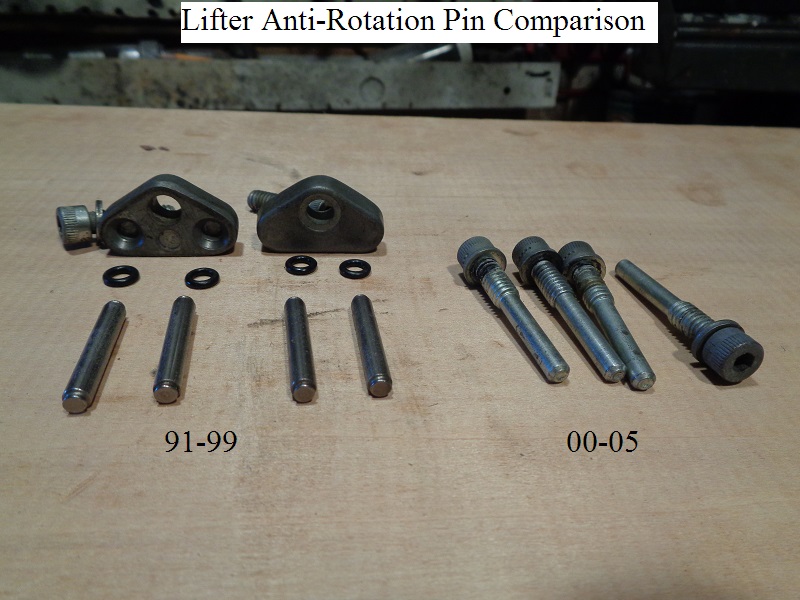
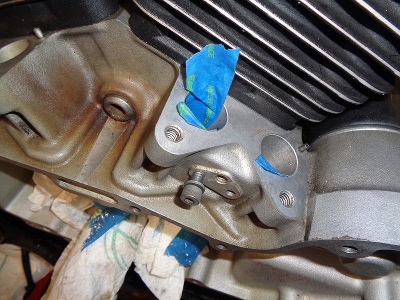
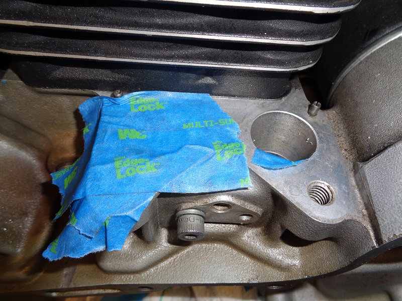
| 91-99 lifter pins vs 00-05 lifter pin screws 7) | |
 |  |
Considerations Before You Begin
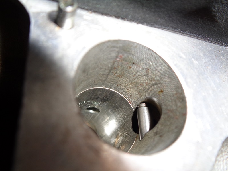
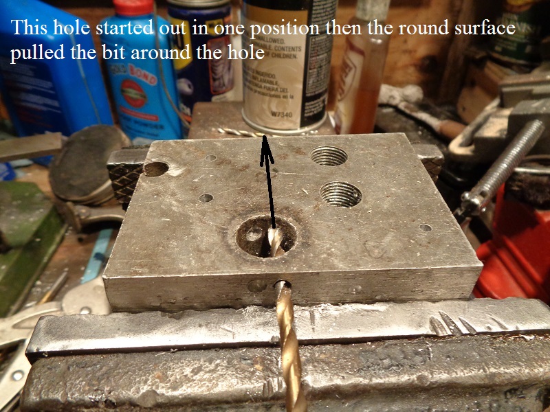
The end of the pin in the pic below bumps into the circular wall you have to drill into.
Notice how the left side of the pin touches the wall and the right side doesn't.
The pin diameter is split between the lifter bore and the pushrod tube drain.
The pin sits just a few thousandths away from the lifter flat also.
 8)
8)  9)
9)
Simplified drawings of the upgrade:
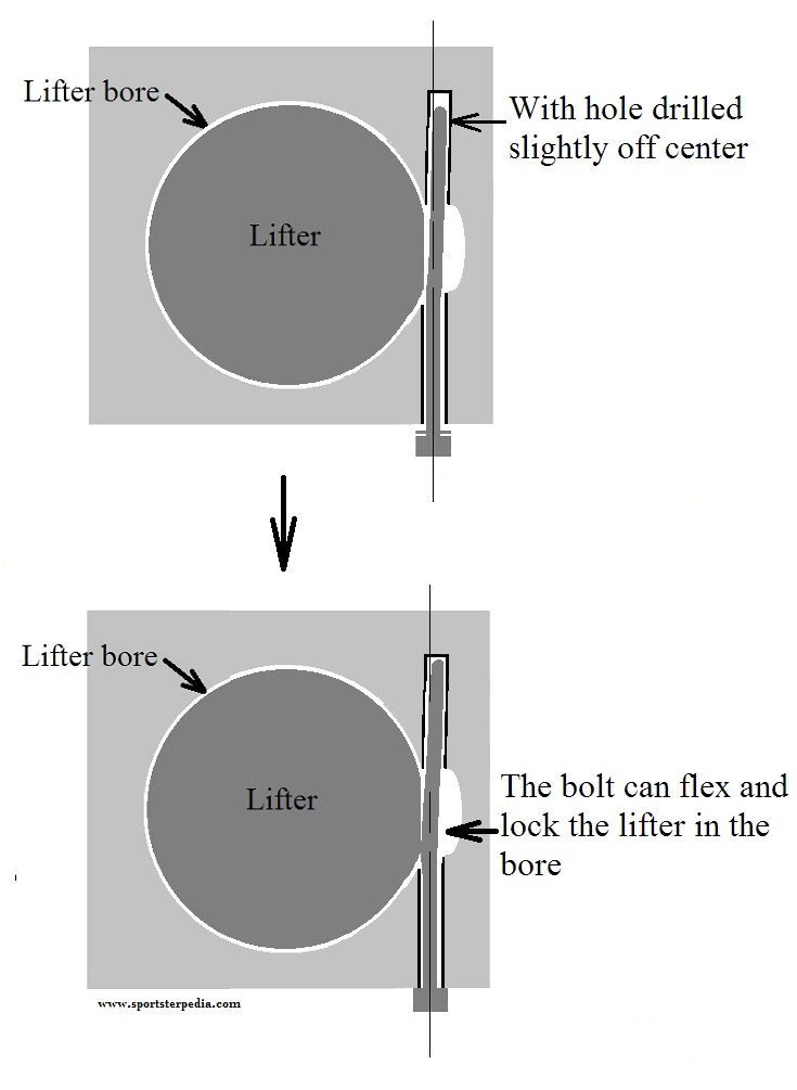
Caution: The 3/16” hole has got to be drilled straight, else the screw can lock up the lifter when installed.
The drawing on the left is a perfect scenario as the screw should be installed.
The drawing on the right represents what can happen if the hole is not drilled straight.
In this case, the hole is drilled off center and the threads were cut straight.
The screw slid in the hole fine but it cinched up close to the lifter when tightened.
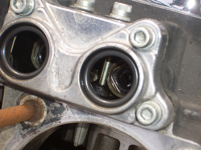
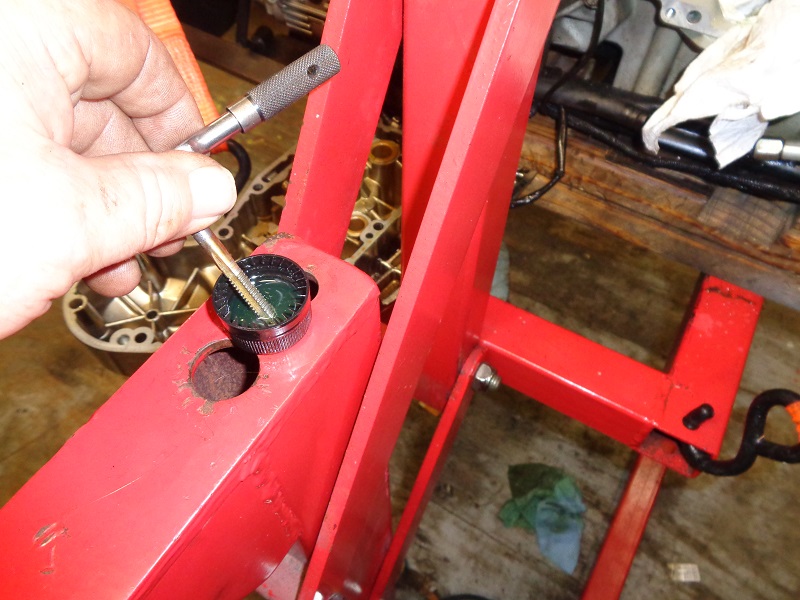
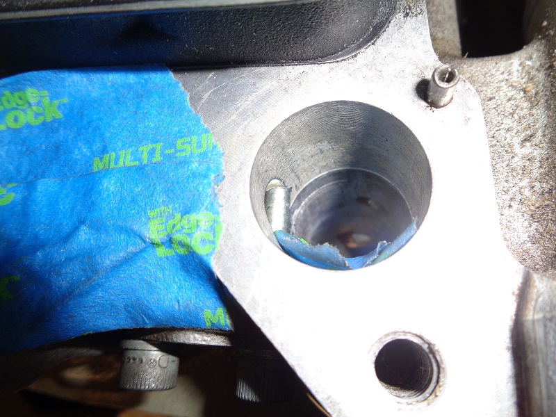
Factory tappet pin clearance on an 05 engine.
 11)
11)
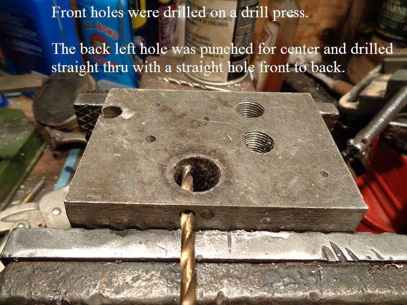
Below is an example gone wrong using a scrap piece of aluminum.
The big hole represents the pushrod drain hole beside the lifter bore.
The hole being drilled represents the back hole needed for this mod.
The front holes were dilled straight in a drill press.
The back holes were drilled with a hand drill.
The left back hole was drilled straight thru using a center punch to keep the drill bit from wandering.
The right back hole was attempted to drill without a center punched and the bit wandered off.
 |  |  |
This above was a practice run but when drilling on the engine, you have one shot get a straight hole the first time.
And there are four holes to drill equaling four separate chances of getting them all right or one or more wrong.
That's why this is best done at a reputable machine shop with the cases split and the right case on a milling machine.
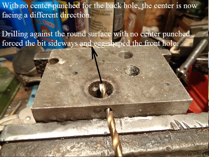
There is no way to get a good center punched on the back wall to be drilled.
The 3/16“ drill bit is a slip fit into the existing 3/16” outside hole.
And even then, the round hole at the back of the wall will try to pull off a center punch.
The hole you will need to drill in the back wall for the new pin has to be drilled straight with the original outboard hole.
If this hole is not straight with the outboard threads you'll have to tap, it can cause the lifters to bind up.
There are a couple things you can try to help ensure the hole is straight.
It is advisable to practice on a scrap piece of aluminum before drilling and tapping into the engine.
The hole to be drilled needs a close tolerance.
A center must be established before drilling with the 3/16“ bit.
Else the bit can wander slightly and create an off centered hole.
There is plenty of meat in the front hole to hold the bit steady for drilling the back hole with just a hand drill.
The front wall is thicker than the length of threads on the screw.
The difference is the vertical circle you're drilling into. It will force the end of the bit sideways with the bit still being straight thru the front hole.
Drilling the hole straight
Below are some ideas to help keep the drill bit straight through from the front to the back hole while drilling.
However, outside of going it alone with a hand drill and a bit, there still is a certain amount of precise required.
- Use sharp drill bits and a sharp tap.
- A dull bit will mushroom the sides of the hole into the bore and can hinder lifter movement when installed.
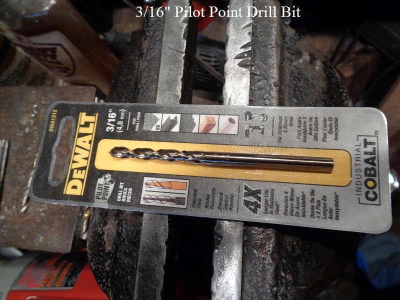
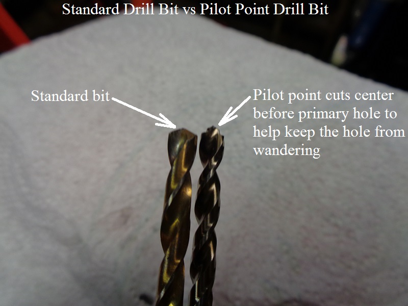
- A pilot point drill bit can be used to drill the pin holes deeper.
- It has a built in 'center bore' on the end.
- It cuts center first and the fluted cutter comes in to cut the primary hole.
- This helps to keep the bit from wandering and keep the hole centered throughout the cut.
- Try a using a hand held 3/16” hollow sleeve as a guide. 12)
- You can use a hand held 3/16“ sleeve with a smaller bit inside as a guide to make the initial center for the bigger 3/16” bit.
- The sleeve should be a close fit thru the front hole to align with the rear hole location.
- The hollow sleeve is held firm to the back wall and in perfect alignment with one hand (being long enough to reach out side the front hole).
- The smaller pilot drill bit is inserted thru the (same size) hole in the sleeve to drill a small (center) hole in the back wall.
- The center bit doesn't have to go the entire pin length distance but far enough to allow the 3/16“ bit to bite to that center.
- Then the 3-1/6” bit is inserted (without the guide) to drill the back hole using the center hole you just made.
- Cookie cutter sleeves you'd buy at the hardware store are not always flat on the end or perfectly round. 13)
Then you have to drill a pilot hole (straight) through.
If this hole is off center, the hole in the back wall will be also.
In going with the adage of the hole being be 1/2 the O.D., the pilot hole would around 9/32“.
The smaller the drill bit, the more it will flex while drilling (especially if you push on it).
Go slow and let the bit do the cutting.
A machined sleeve may work better but it would need to be a tight slip fit and not loose to let the circular motion of the drill point pull it towards the small hole.
- You can tap the hole first and then center drill the back wall through a bolt. 14)
- Basically, you use the bolt as a sleeve.
- Here are a couple videos showing this concept by bustert of the XLFORUM
- The same considerations apply here as with using a sleeve as in above with the exception of;
- The bolt can be threaded into (and dead ended at) the back wall.
- This would help steady the 'bolt sleeve'.
- Thread clearance can be a problem.
- Tapping with the standard pre-drill size for 1/4”x20 leaves a slight play in the threads when a bolt is turned into the hole.
- This is normal. But when the bolt dead heads into the back wall, the thread clearance can allow the end of the bolt to shift.
- The pre-drill hole size for 1/4“x20 threads is .201”
- This leaves a little wiggle room in the threads (aka wiggle room for the drill bit on the back wall).
- If you used a .196“ or even a .199” pre-drill, the threads would have a little less clearance to wiggle.
- You'd just have to be more careful while tapping.
- You can go it alone with a hand drill. 15)
- This is the easiest route and probably the way most would try it at home.
- However, results may vary.
- There is nothing scientific about it.
- It's best to practice on a scrap piece of aluminum to get the feel for it.
- Take your time, go easy and let the drill bit do the cutting.
- See Using a hand drill only below with pics of the using this method.
| Pilot bit comparison to standard drill bit. 16) | |
 |  |
Installing the Screws Using a Hand Drill Only
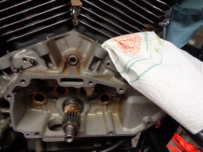
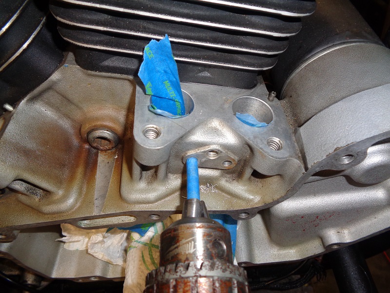
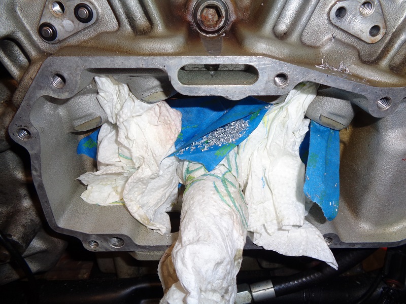
First, clean the bores with solvent on a rag (Acetone used here).
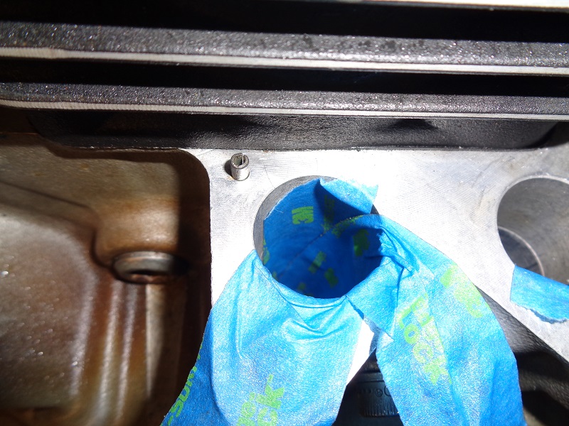
The oiling holes coming into the bores need to be taped of so aluminum shavings don't get into them.
(tape won't stick to oily surfaces)
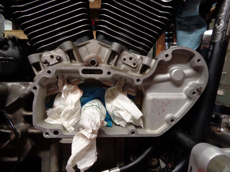
Tape off the oil inlet holes on the outside and the blind rifling holes on the inside of the bores.
Tape the camshaft bushings and splash holes in the wall in the gearcase.
Tape around the pinion shaft bearings and cover the shaft.
| Protect the gearcase oiling holes from aluminum shavings. 17) | ||
 |  |  |
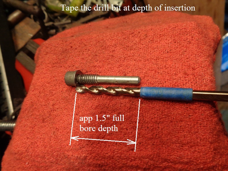
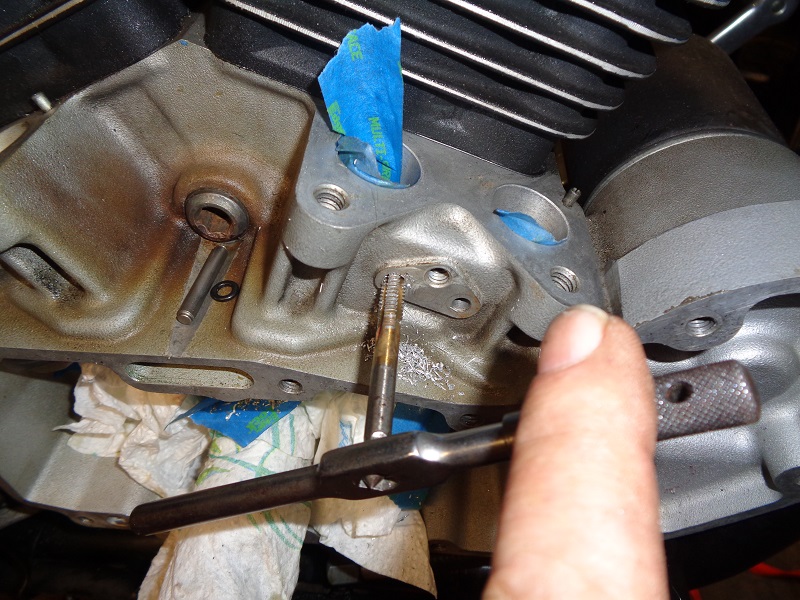
Drilling the pin hole deeper
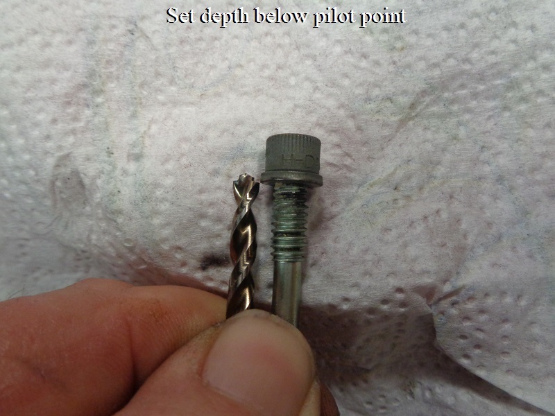
Measure the length of the pin to be installed and tape the drill bit to reflect max depth of the hole to be drilled.
Mark the drill bit the length from under the washer to the end of the pin.
This way you don't drill too far and into the crankcase area by mistake.
| Mark the depth to drill with tape. Start below the pilot point. 18) | Dip the bit in oil before drilling. 19) | |
 |  | 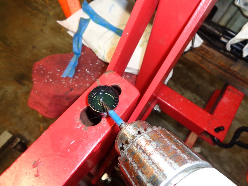 |
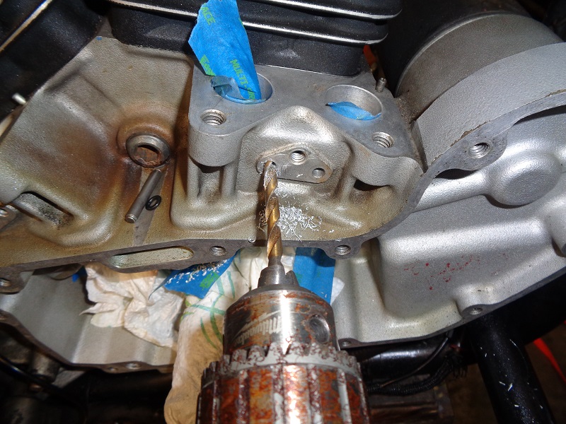
Insert the drill bit into the existing 3/16“ hole and lightly press the against the back of the hole.
Use the drill on low speed and let the bit do the cutting. Only use light pressure toward the hole.
It takes longer to cut the new hole this way but too much pressure added can twist the bit sideways and move the center of the hole.
| Drill the hole to the end of the tape with the 3/16” bit. Then stop and pull the bit out of the hole. 20) | ||
 | 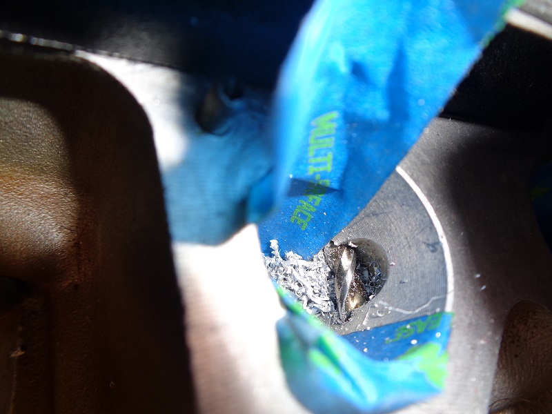 |  |
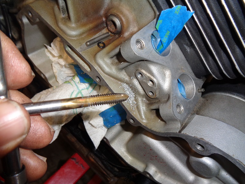
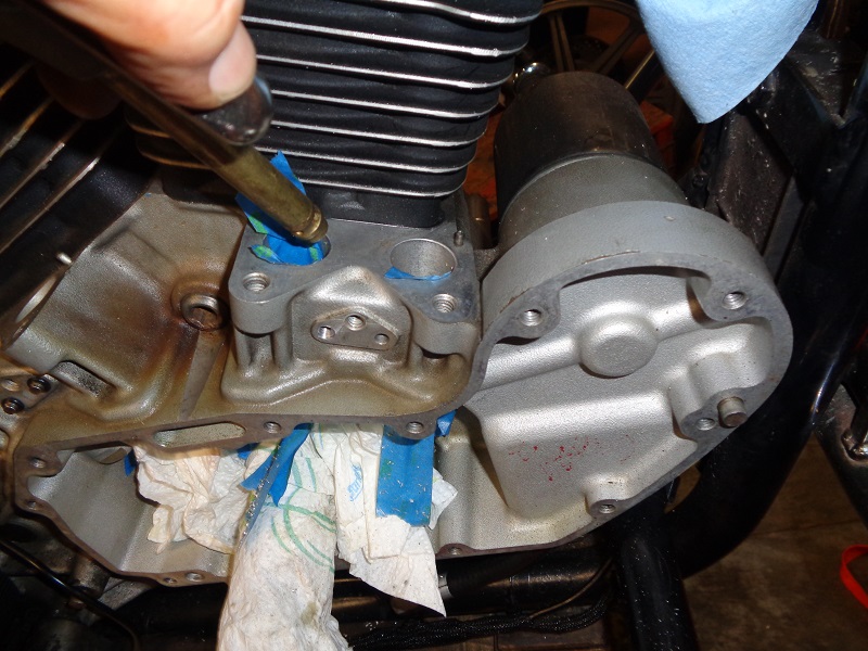
Tapping the outboard side
The outside hole now has to be pre-drilled with a .201“ bit for 1/4”x20 threads to be cut for the pin screw.
Line up the bit as straight as possible.
Caution: The hole center can be changed if not careful. The bigger bit will follow the existing hole.
But leaning off center while drilling can wallow the hole.
This could move center as well as create a wider (egg shaped hole) and looser fitting threads in the end.
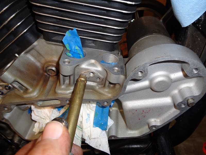
| Swap to a .201“ bit (pre-drill size for 1/4”x20 threads) and drill the outside hole only. Apply oil to the 1/4“x20 tap, line it up straight and slowly cut the threads. Turn the tap in about 3/4 turns and back it out, turn it in until it stops, cut another 3/4 turn, back it etc. 21) |
||
 |  |  |
| Remove the tap periodically, clean the shavings off of it, oil it and run it back in to continue threading. Blow the chips out with compressed air. 22) |
||
 |  |  |
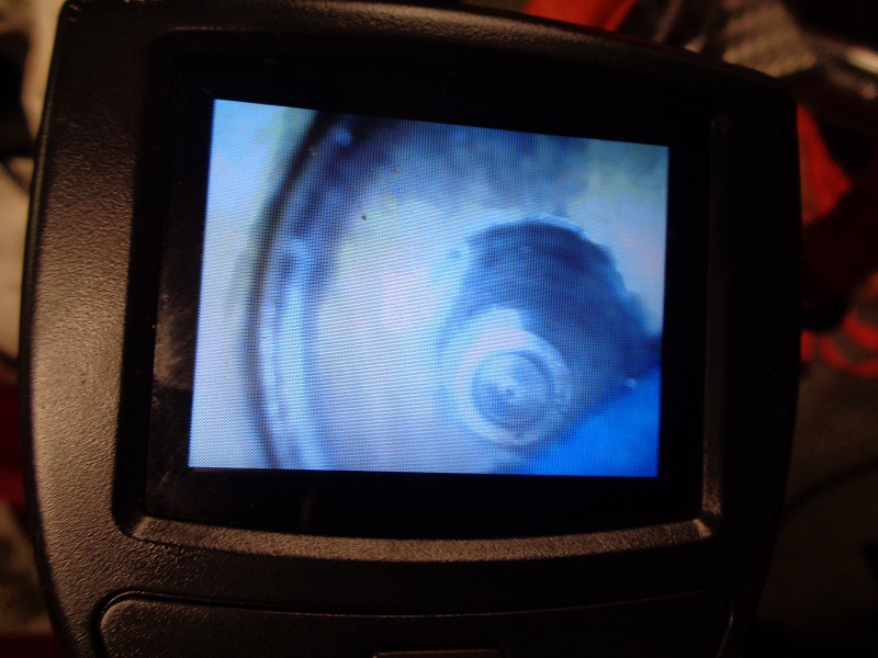
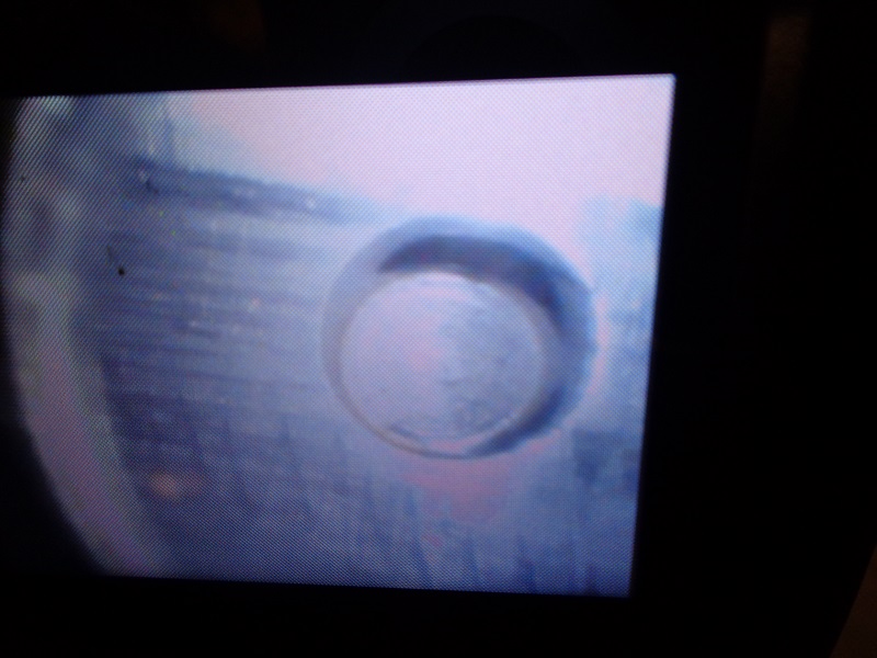
| You can use a small inspection camera to check the oiling holes for aluminum shavings. 23) | This is the new extended pin hole. 24) | |
 |  |  |
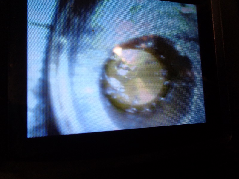
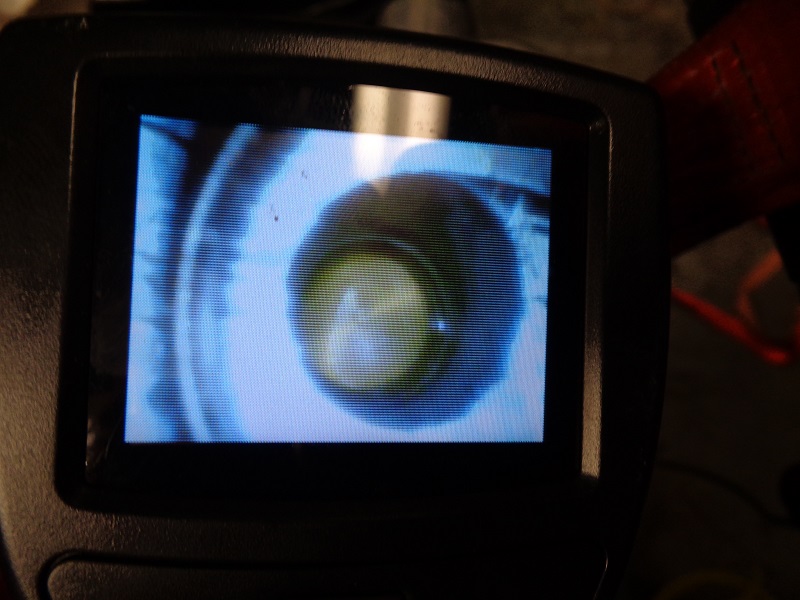
| This is the oil feed hole in the bore. 25) | The blind hole on the inside of the bore got splashed during blowdown. 26) | A straw into the air gun placed in this hole removed the chips. 27) |
 |  |  |
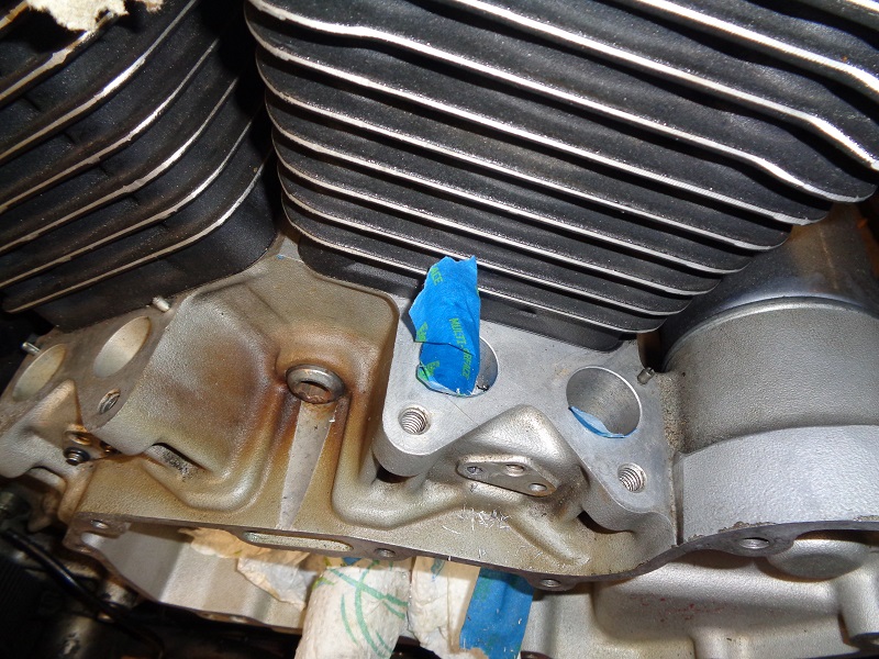
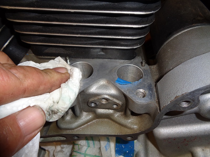
| Clean the area in and on top of the bore, reapply tape as needed, 28) | ||
 |  |  |
| Cover the hole you just finished and repeat for the remaining bores. 29) | ||
 |  |  |
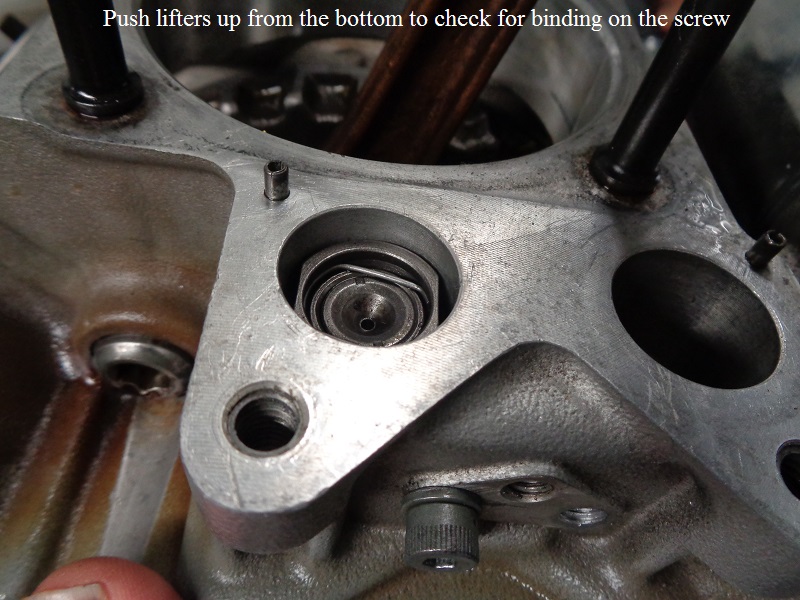
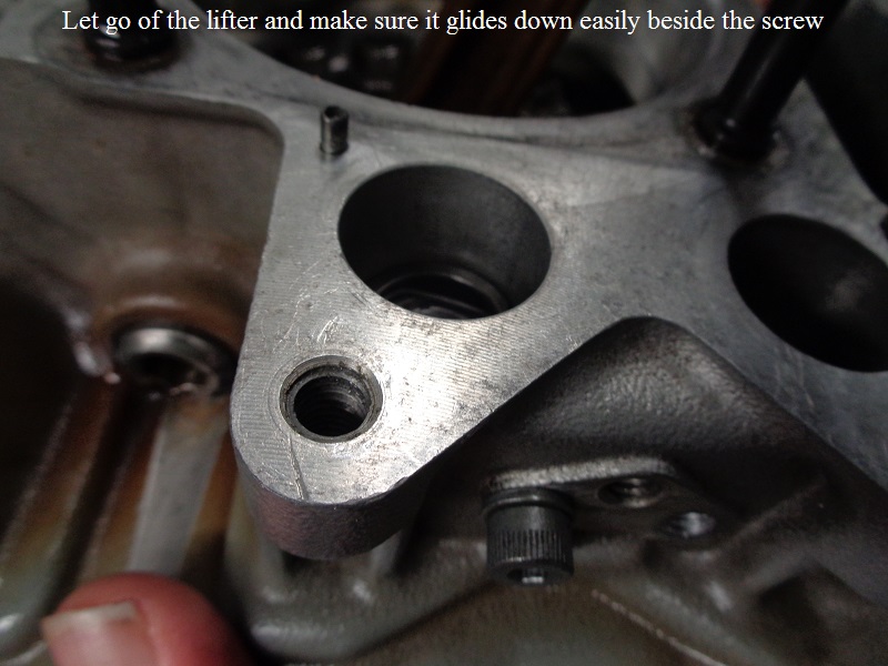
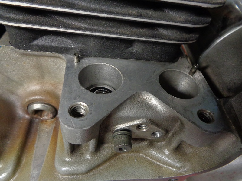
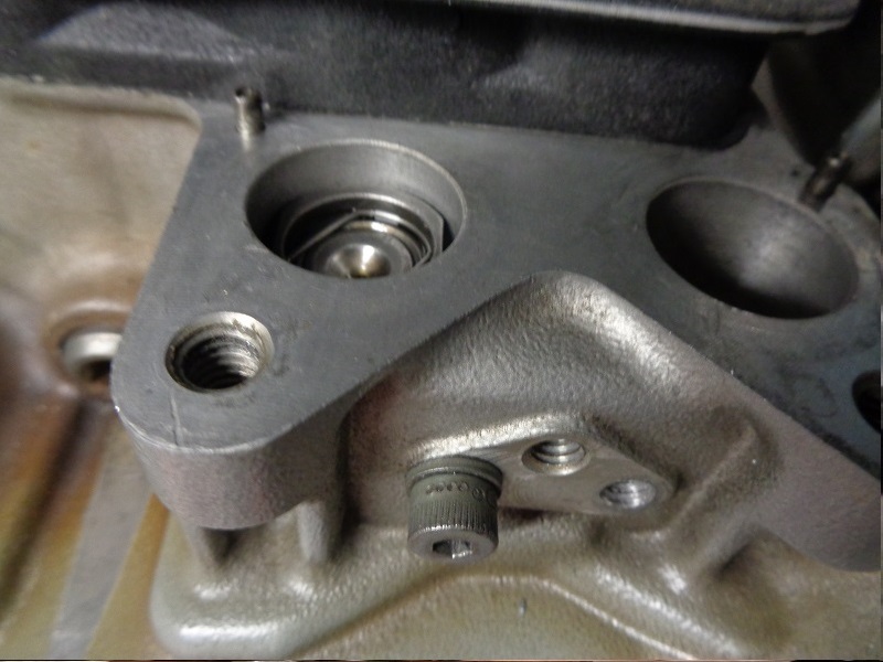
Test Fit the Lifters
Test fit the lifters movement up and down with the screws installed.
With each pin in place, you should be able to push the lifter up from the bottom with your finger with no resistance from the pin.
The you should be able to let go of the bottom of the lifter and see it glide down and stop in the lower part of the bore by itself.
 |  |
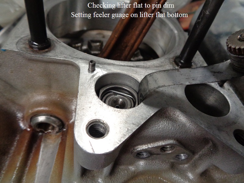
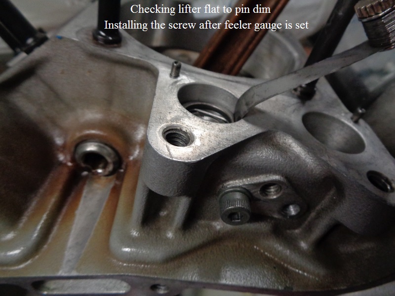
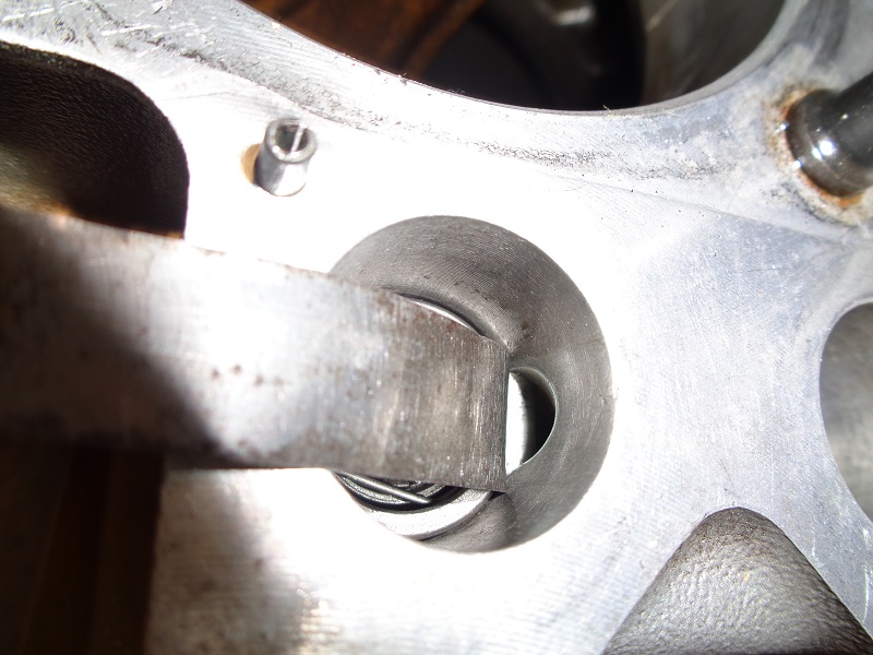
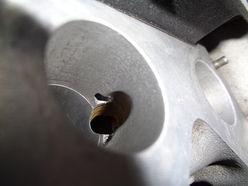
You can use a feeler gauge between the pin and lifter flat.
The gauge below has wide blades so the lifter was raised without the pin installed, lowered and the pin was inserted.
In this case, start with the smallest feeler gauge and work up in size until the screw will no longer go in the hole.
The lifter below has app .001” clearance to the pin screw.
 |  |  |
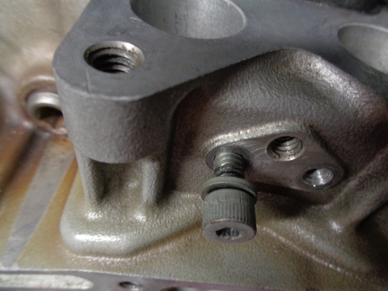
If a screw locks up a lifter when installed, the back hole did wander away from center.
The lifter below was moving fine with the bolt inserted and threaded to the head but not tightened.
It locked up as soon as the bolt was torqued to 10 in lbs.
Upon tightening, the bolt flexed in the middle as in the example diagram above against the lifter.
 |  |
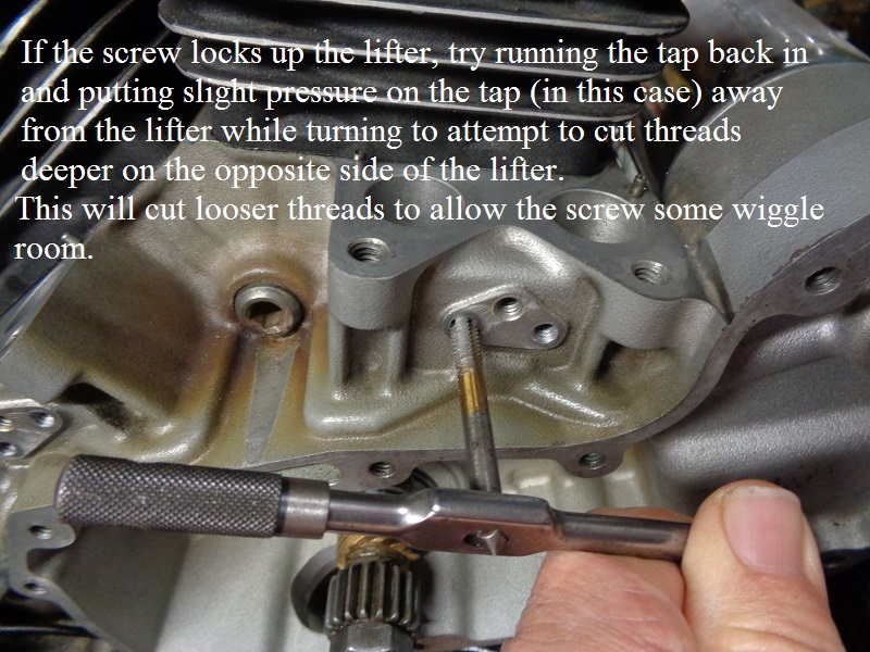
If the lifters lock up
Try running the tap back in and putting slight pressure on the tap (in this case) away from the lifter while turning to attempt to cut threads deeper on the opposite side of the lifter.
It worked in the pics below. Afterwards, the lifter moves up and down freely without binding with the bolt tightened.
 | 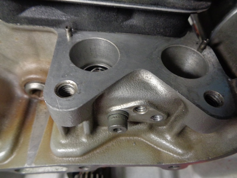 |
With the stock pins on a worn engine, there was a slight circular twist possible to the lifters with the pins installed.
Now, with the screws in place, the lifters don't twist anymore and all have easy up and down movement.
The threads are a looser fit on the threaded hole that was adjusted which allows the bolt to tighten without cinching up.
But the integrity of threads are still intact.
 |  |  |
But again, this is better done at a machine shop.