Table of Contents
This is an old revision of the document!

EVO: Engine Mechanicals - Sub-04B
Rocker Box / Rocker Arm Inspection and Servicing
See also in the Sportsterpedia.
The forgoing is a compilation of maintenance and clearancing advice from the XLFORUM.
Most of these aren't mandatory unless you notice a problem upon inspection.
If problems are found, below are some examples of how those have been addressed.
Clearancing the Rocker Boxes
High lift cams or changes in the valve springs can cause contact in the rocker box. 1)
When you have high lift cams, as the rockers push your valves open they are also putting a sideways pressure on the valve stems. 2)
Even if you haven't installed performance parts or have acquired a bike that you're unfamiliar with;
Inspecting the rocker boxes can clue you in to possible problems from wear before it's too late.
If something were to wear down or overheat or come lose for instance. 3)
Worn valve guides can also offset the spring travel and let them hit the covers. 4) 5)
When using bronze valve guides, they are cut shorter to allow for valve clearancing.
That causes the valve guides to wear out in an hour glass shape.
When the valve retainers hit the rocker boxes it pushes the valves sideways and wears out the inside of the valve guides faster than usual.
Adding clearance in the rocker box is not described in the FSMs since the factory took care of that when they built it. 6) 7)
But it's incredibly important with OEM modifications or a performance build to check clearances in the rocker box.
Anytime you deviate from factory setups, it's not optional to overlook this step.
Unfortunately, it's also one of the hardest steps to get people to pay attention to.
Professional mechanics will sometimes skip this step (or take it lightly) more than non-professionals do.
Take this seriously.
Upper Rocker Box / Cover (All)
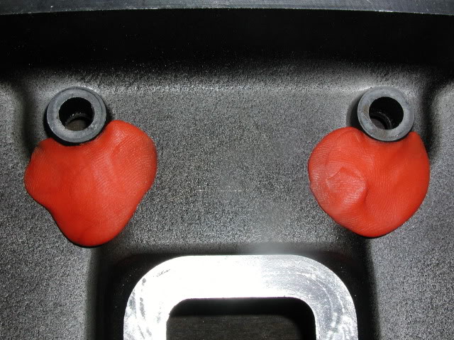
Check the clearance between the rocker arm and the underside of the rocker box cover. 8)
With high lift cams, the rocker arm will often make contact with the rocker box top.
You can use a little play-dough or modeling clay to check this clearance.
Place it in the areas as in the pic below, install it and turn the engine over.
Then remove the cover and see if anything got up intp the clay and where.
Pull the tops and look for little marks on the inside. 9)
There shouldn't be any outside of factory casting marks.
Rocker or pushrod contact will appear as marks that shouldn't be there.
If any are found, a little strategically located grinding cleans it right up.
Occasionally, 536 cams can cause the rocker arms to hit the rocker box tops (on the pushrod side).
This is rare, but it can happen.
Contact here should cause any damage, but it'll cause noise and leaks. 10)
A lot of rocker box top leaks have been traced to this.
Middle Rocker Box Spacer (91-03)
This is a mod to curtail the issue of puking oil out the breathers. 13)
86-90 engines do not have a crankcase breather valve incorporated into the rocker boxes.
However, the first answer would address other known factors for wet sumping.
This mod consists of;
Chamfering the umbrella hole to 60 degrees (included angle),
And drilling out the existing drain back hole to 1/8“.
To the extent the drain back hole is enlarged, it bypasses the umbrella valve.
Maybe 1/8” isn't enough to cause an issue,
But the umbrella valve is what keeps the air inhalation/exhalation to a minimum,
And inhalation/exhalation is what carries oil out the breathers.
So you don't want to bypass it any more than necessary.
You could probably do the chamfer, but not the drain hole enlargement.
Then, if you still have the issue, you could also drill out the drain hole.
The rocker box middles use the same casting for both the front and rear cylinder.
And there's a facility for the umbrella valve on both ends of each middle spacer.
So you can try this, and if it doesn't work, just move the umbrella valve to the other end and use the rocker box middle on the other cylinder.
In other words, this mod is undo-able, a one time thing.
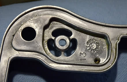
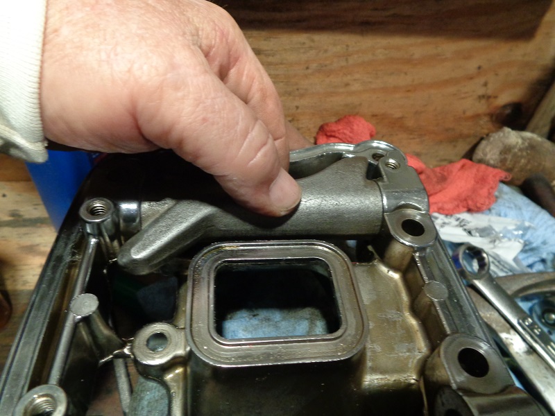
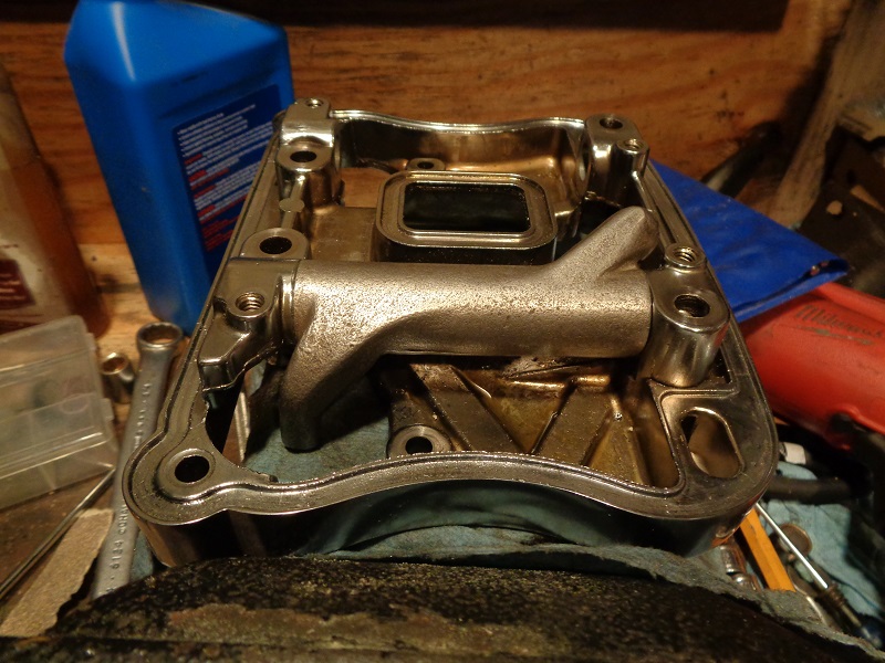
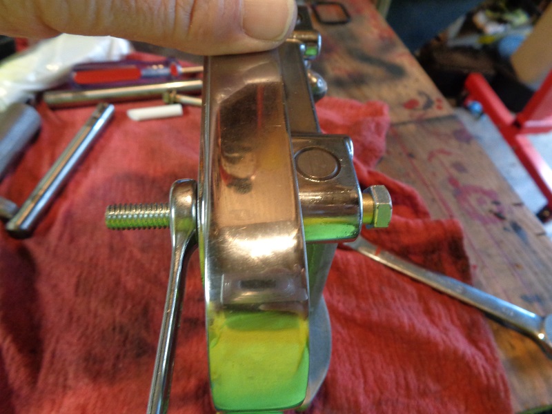
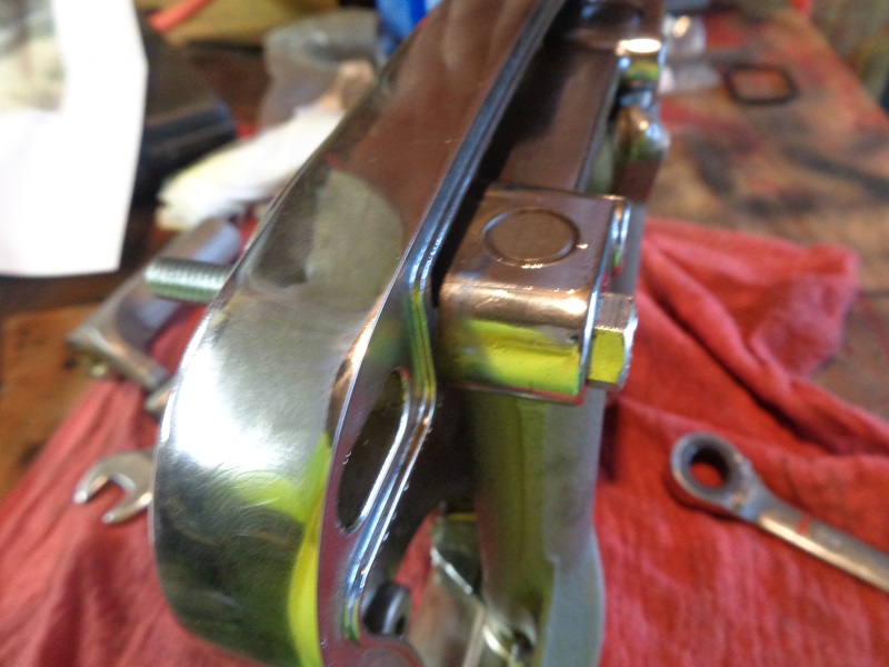
The umbrella hole is the one in the middle of the picture below.
The drain back hole is the tiny little hole to the right of the sideways 13 in the picture.
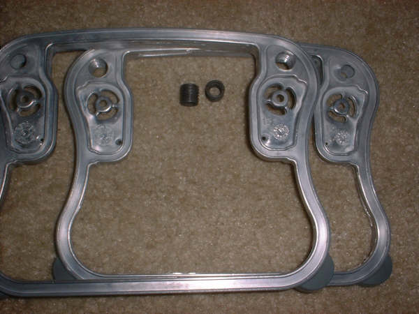
Another suggestion is to enlarge the tiny oil drain from ~.070 to .09375 and add threaded inserts as oil standoffs. 15) 16)
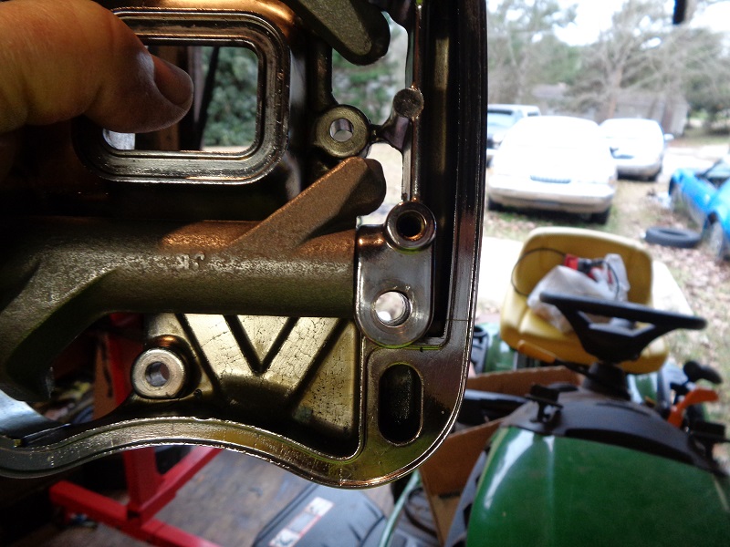
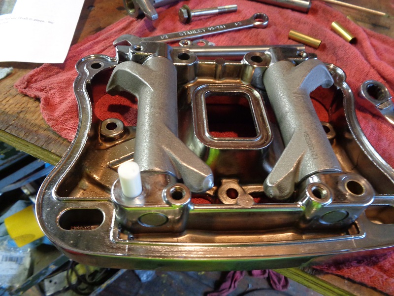
Looking at the pictures below, you can see 3 holes that are in a roughly oval shape area in the corners of the middle rocker box cover. (2 per rocker box, only 1 is used per cylinder)
With each downstroke, the air in the crankcase is forced thru the umbrella valve.
The air has an oil mist in it.
The oil is supposed it settle out in this little chamber and drain back to the cylinder head thru the tiny oil (bottom of oval area).
Slightly enlarging the little hole lets the oil drain back easier.
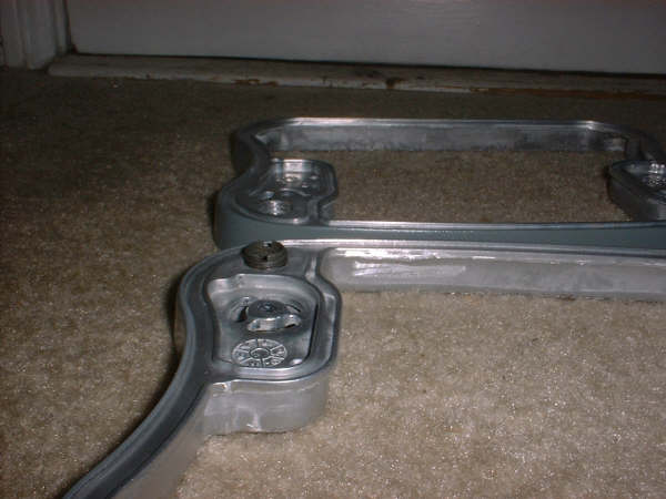
Air that enters this oval(ish) chamber has to go somewhere.
So it goes out the big hole on top, thru the breather bolts and out.
The threaded insert just provides a lip around the hole.
So any oil that drops out of suspension around the hole won't drain out the breather.
It just makes it a little bit harder for oil to go out the breather.
The inserts below were left overs from another project.
You can use anything that does the same thing.
You can buy a product online called “Slobber Stoppers”. https://www.ebay.com/itm/200917426709
It comes with threaded barrels similar to the threaded inserts below to eliminate oil mist from getting into the air cleaner.
Lower Rocker Box / Cover (All)
Check for Warpage
When you have the lower rocker boxes removed, be sure to check their flatness on pane of glass or other extremely flat surface. 19)
Spring Clearance
The most critical clearance in the rocker box is the clearance between the valve springs and all areas of the rocker box around it. 20)
If the valve spring or retainer is allowed to touch the rocker box, it forces the valve to land sideways on the seat.
This causes seat recession and the resultant loss of seal, which of course saps power among other things.
Performance springs are larger in diameter than the factory springs and they will generally want to touch the rocker box.
You absolutely must provide a minimum of .025“ of clearance all around the valve spring and retainer.
Grind or file on the rocker box as needed to achieve this clearance.
Note that with a beehive spring pack, this probably won't be an issue, but check it anyway.
With a conventional straight wound performance spring pack, it will almost certainly be an issue.
Check for clearance issues between the valve spring / collar and the rocker box. 21)
When running big springs and cams, the additional lift can run the springs into the inside edge of the rocker.
In that case, the rockers should be clearance for the bigger springs.
This is more than just a nuisance noise. It will cause valve seat recession.
This means pulling the heads and changing seats, an expensive proposition.
That's one of the nice things about the 7mm valves with beehive springs in the late heads, it eliminates this problem.
| Lower rocker damage from valve spring impact 22) | ||
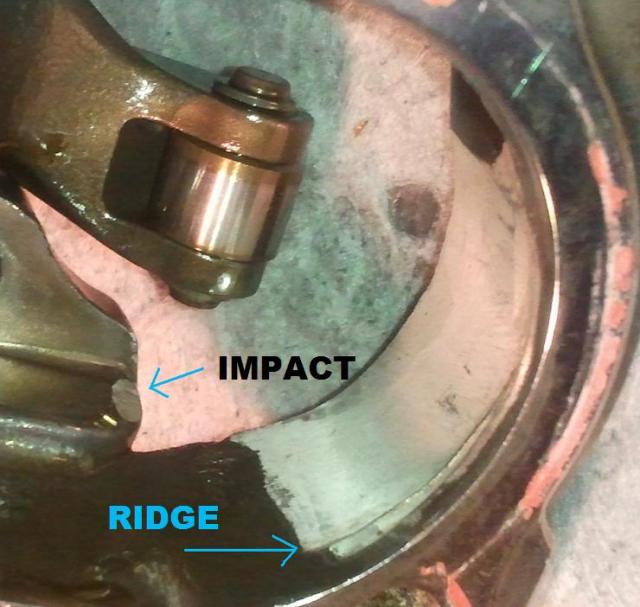 | 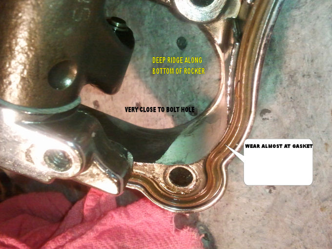 | 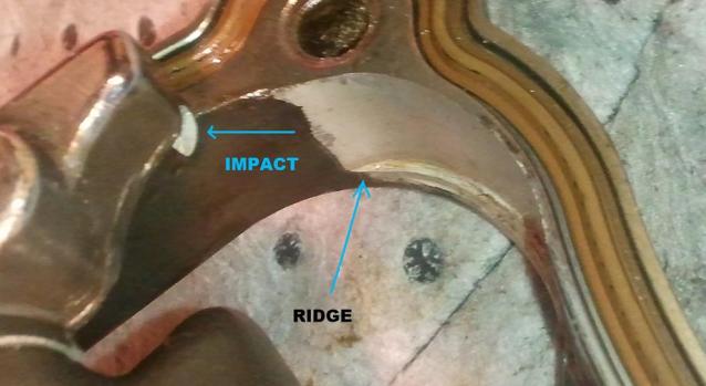 |
Valve spring clearance is a very common issue with high performance straight wound springs. 23)
Back before we went to beehive springs, this was a major headache for us.
People would lose valve seal and swear up and down they clearanced their rocker boxes adequately.
But later on, we'd get their rocker boxes and find spring/retainer gouge marks in them.
No matter what we did, we just couldn't get people to take it seriously.
If those springs hit the insides of the rocker boxes, you WILL get recessed valve seats, not maybe.
This issue went away when we migrated to beehives, thankfully.
It was a major motivating factor behind finding beehives that would work.
But they're not really suitable for all applications in HD motors.
Of course, now we're moving beyond beehives to the next great thing.
What you're looking for is to make sure the spring cannot contact the side of the box.
The clearancing can be done with a drum sander on a dremel type rotary tool 24) or a die grinder.
| Big springs can cause this issue. 25) | The clearancing job doesn't have to be pretty. You're just creating space for the springs to miss the rocker. 26) |
You can use a Sharpie marking pen or other to mark where the springs are too close so you'll know where to relieve the rocker box.
Arm Clearance
This condition was noticed when using S&S roller rocker arms and big cams.
But these areas can be checked while using stock or other rocker arms also.
Symptoms were a ticking noise on the top end on cold starts. 31)
The roller rockers were just grazing the rocker box assembly.
All 4 were just barely nicking the box.
It stopped when the bike got warm and stretched.
Clearance can be done with a die grinder or Dremil Tool.
| Check for wear at the side of the pushrod arms at the box. 32) | |
| Check for wear at the side of the valve arms at the box 33) | |
| You can see where the contact occurs. 34) | |
| After clearancing the box. 35) | ||
| Rockers installed and not hitting the box anymore. 36) | |
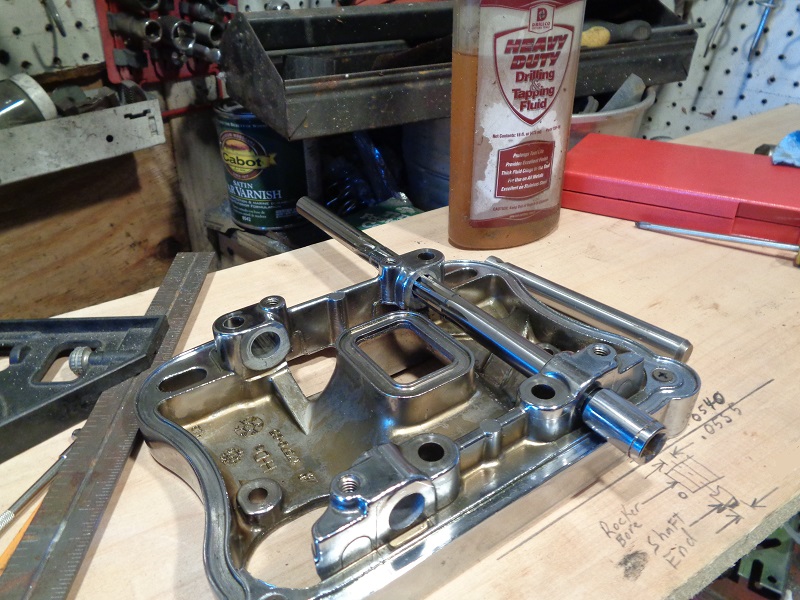
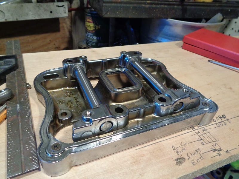
Rocker Arms
The rocker arm shaft is not supposed to rotate from it's installed position.
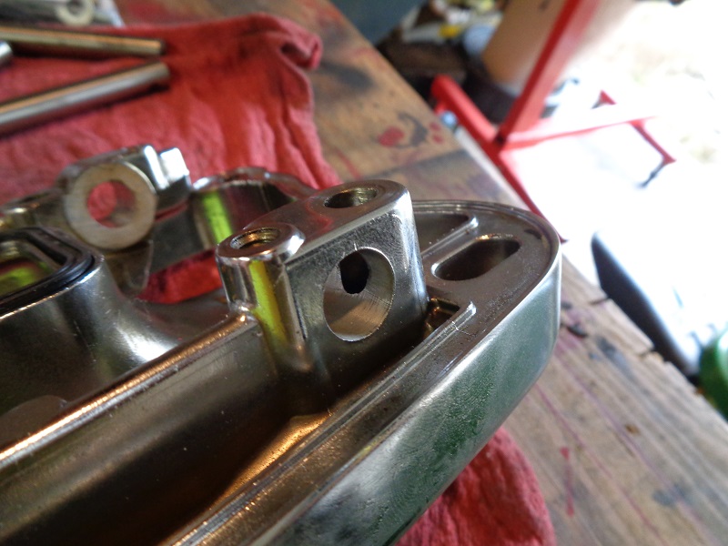
The shafts have a notch in them that the bolt is supposed to butt up against which locks the rocker arm shafts in place. 37)
However, the bolt hole is too large which leaves a gap there.
This gap allows the shaft to slightly rotate and hit the bolt which causes an annoying ticking/tapping noise.
Normally what rotates is the rocker arm itself.
The bushings in the rocker arm pivot around the rocker arm shaft.
The shaft runs through bushings on both ends of the rocker arm.
These bushings can expand due to normal wear.
The FSM suggests visual inspection and measuring of specific clearances as outlined below as a guide to when to replace parts.
Ultimately, it's an individual judgment call as to replacing parts that are within measured specs.
Rocker Arm Specs
Service wear limits are a guideline for measuring parts that are not new.
Replace parts when their measurements exceed the wear limits below.
If wear limits are not given for a part, refer to the new install specs. 38)
| Rocker Arm Specs | New Install | Used Service Wear Limits |
| Shaft in bushing (loose) | .0005” - .0020“ (.013 mm - .051 mm) | .0035” (.089 mm) |
| End play | .003“ - .013” (.08 mm - .33 mm) | .025“ (.64 mm) |
| Bushing fit in rocker arm (tight) | .004” - .002“ (.10 mm - .05 mm) | No variance |
| Rocker Arm Shaft Specs | New Install | Used Service Wear Limits |
| Shaft fit in rocker cover (loose) | .0007” - .0022“ (.018 mm - .056 mm) | .0035” (.089 mm) |
Inspection before removal
Check the end play of each rocker arm
The ends of the rocker arms can wear down the area where they touch the lower rocker box.
- Push the rocker arm to one end.
- Check the clearance between the other end and the cover with a feeler gauge.
- The FSM suggests to replace the rocker arm or lower cover or both if the end play exceeds .025“ (.63 mm). 39)
| Checking end play 40) | |
Check Arm Contact at Valve Spring
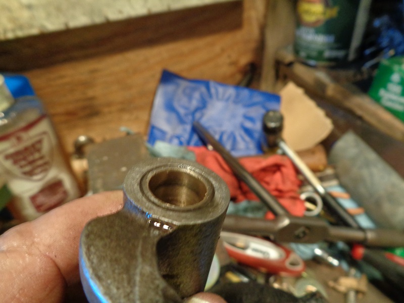
Inspection after removal
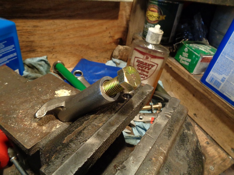
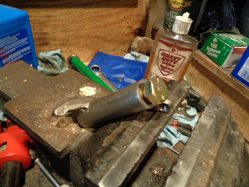
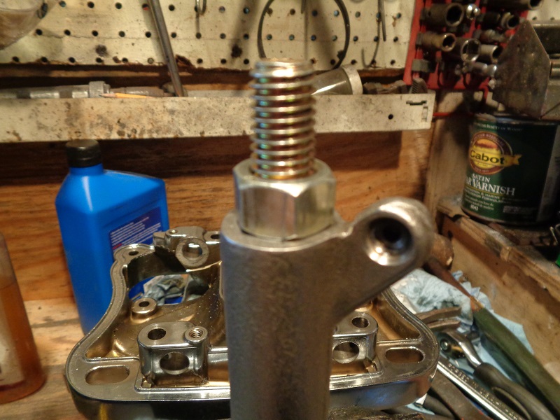
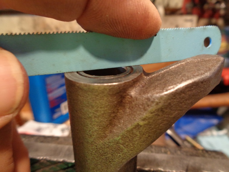
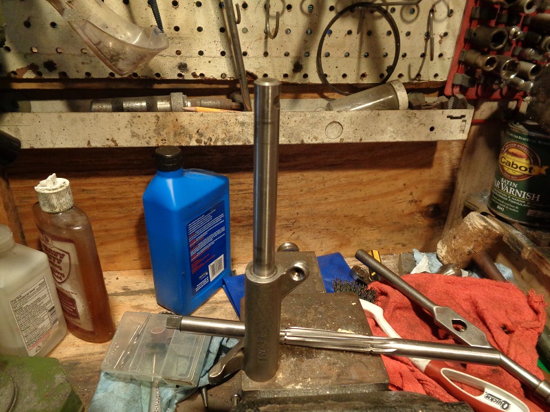
If the rocker arm shafts will not slide out on their own;
You can remove them by tapping them out using a hammer and a soft metal punch. 43)
 | 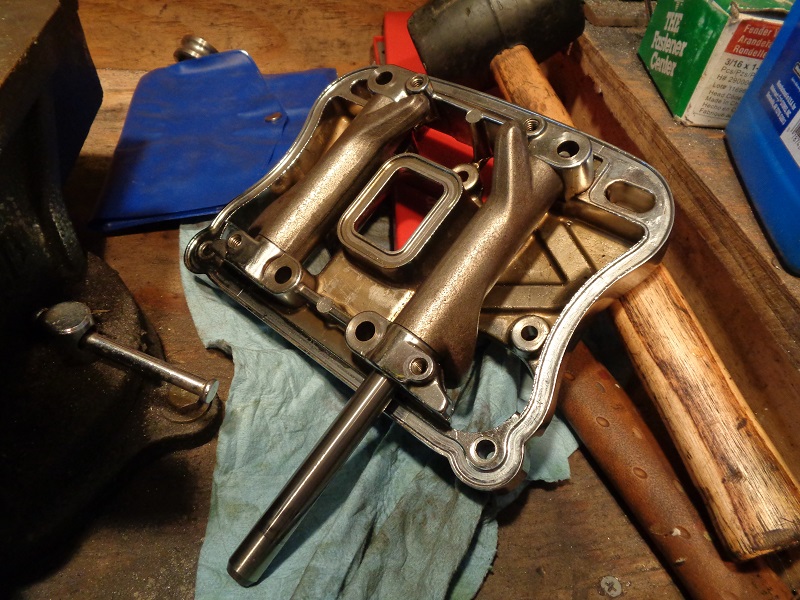 | 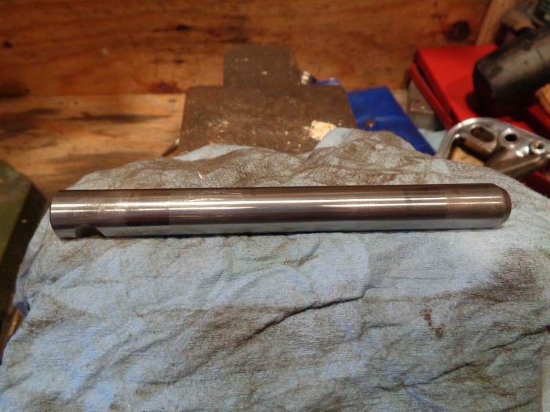 |
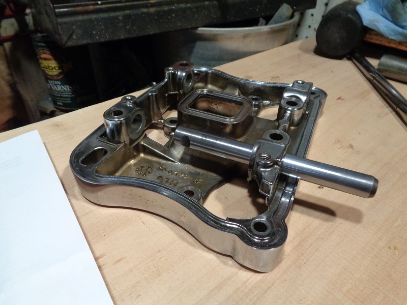
You'll be measuring for an 'out of round' condition of the rocker arm and associated parts.
Most of the wear in the rocker arm shafts and bores results from up and down movement of the pushrods and valves. 44)
This can result in an out of round condition on either or all of these parts.
(more wear in the top and bottom than the sides)
When measuring the rocker arm shaft end, it's bushing or cover bore when new,
Take a measurement and then turn 180° and take another measurement.
The two measurements should be the same in newly installed parts.
Subsequent wear will happen from top to bottom and need replacement.
This could induce noise and expedite wear on the parts.
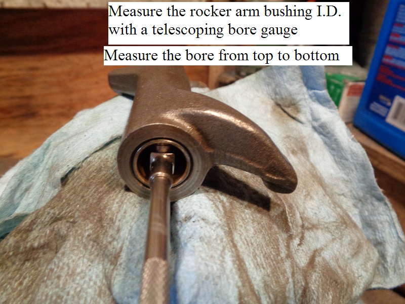
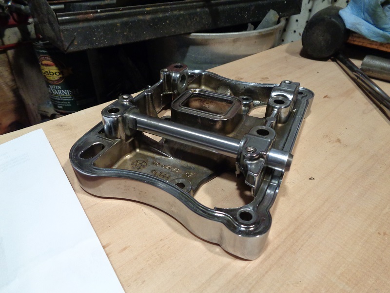
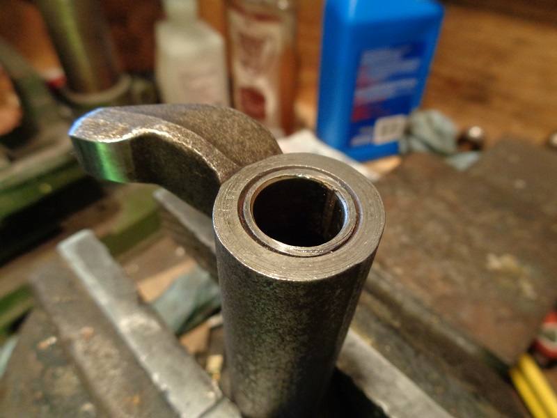
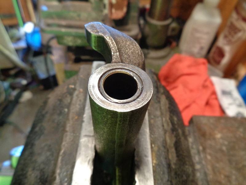
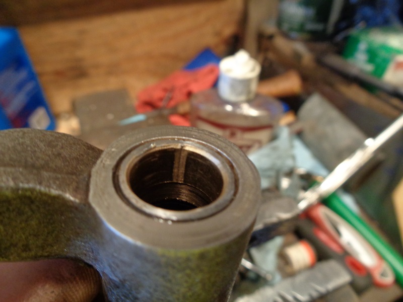
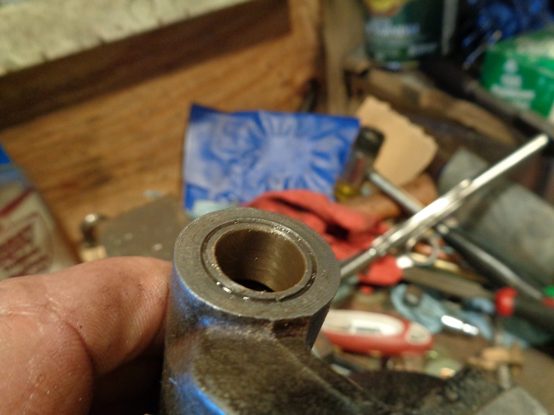
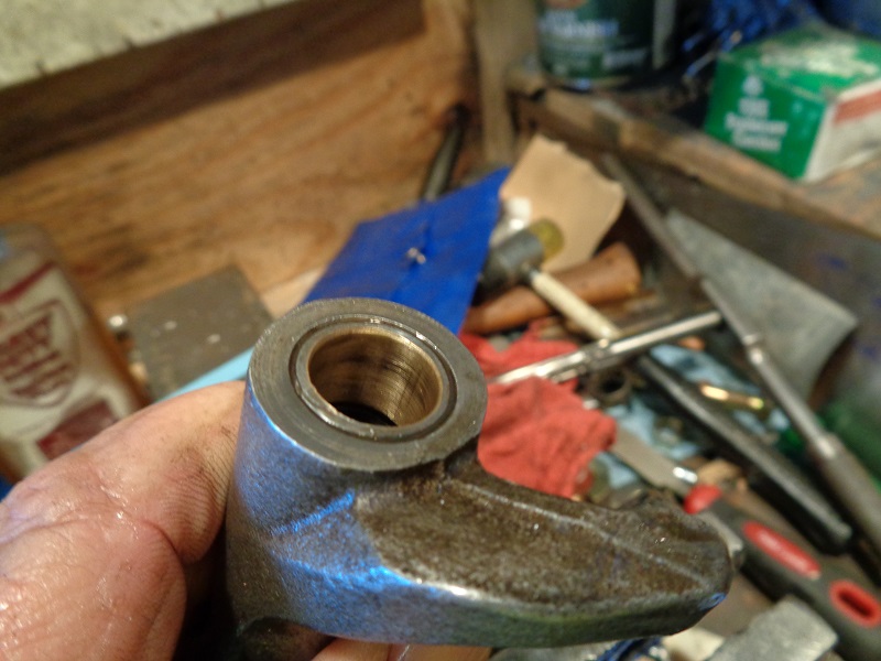
Check the shaft in bushing clearance
All measurements should be taken from the top to bottom position as each part sits while installed as per the FSM.
Both arms on each rocker are being pushed upward during operation.
The load side is on the bottom. That is where most of the wear will be as in the pic below.
 45)
45)
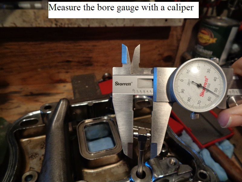
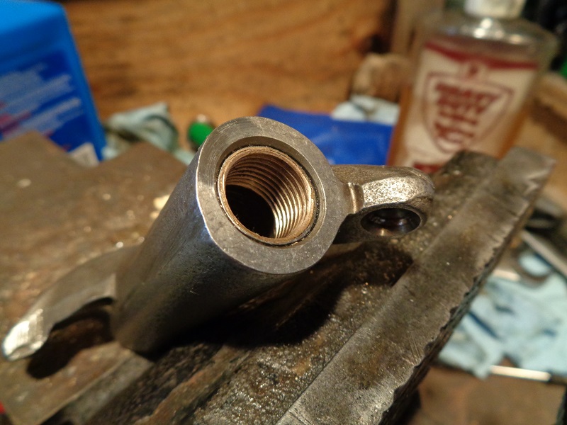
- Measure and record the rocker arm shaft dia. at each bushing area with a caliper.
- Measure and record the I.D of the rocker arm bushing with a telescoping bore gauge and caliper.
- Subtract the shaft dia. from the bushing I.D. and match that number against the wear limit specs.
- If the bushing is at or past the service wear limit, proceed to “replacing the bushings” as in below.
 |  |  |
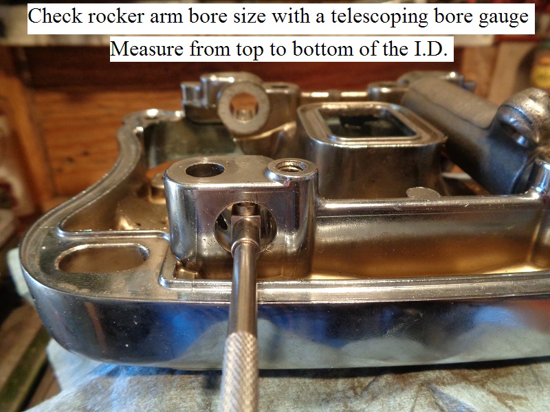
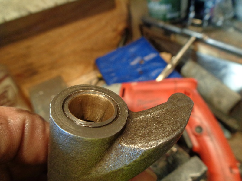
Check the shaft fit in the rocker cover
An assembly bolt runs through the gap near the end of the shaft.
The gap is wider than the bolt.
This allows a slight movement of the shaft in it's rocker cover bore.
You can check for slight movement there on a running engine: 46)
With the covers off, draw a straight line with a felt marker on the end of the shaft from the cover bore and down the shaft.
Then fire up the engine. At idle, if you see any back and forth movement of that line, you have movement of the shaft.
Checking the shaft fit is the same as checking the bushing clearance;
All measurements should be taken from the top to bottom position as each part sits while installed as per the FSM.
That is where most of the wear will be as mentioned above.
- Measure and record the dia. of the rocker arm shaft at each rocker bore with a caliper.
- Measure and record the I.D of the rocker box bore for the shaft with a telescoping bore gauge and caliper.
- Subtract the shaft dia. from the rocker box bore and match that number against the wear limit specs.
- If the either are at or past the service wear limit,
- Check the dia. in the middle of the shaft against the dia. at the end. Both places should be the same.
If the shaft is smaller in dia. on the end, replace the shaft and recheck the measurements.
(this is cheaper than replacing the lower rocker cover) - If the shaft mic's out OK, then replace the lower rocker cover.
 |  |  |
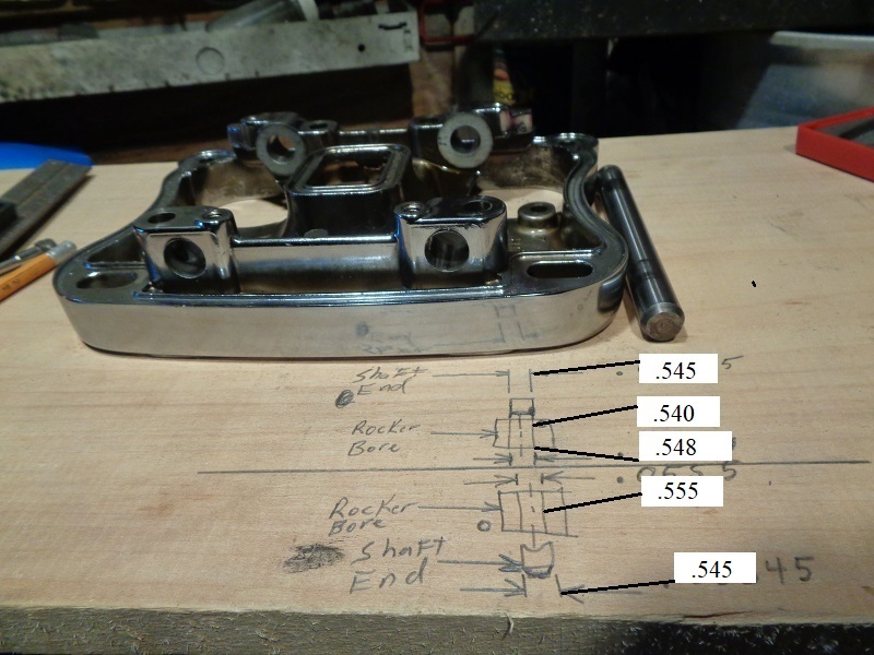
- The shafts below were test fitted to find where the binding was happening.
One end of each shaft slid in easily on one side but would bind up going into the other end. - There was app. .001” clearance on the chamfered end and a press fit on the other.
- Per the specs in the FSM;
Shaft fit in rocker cover (loose)
New Install .0007” - .0022“ (.018 mm - .056 mm)
Wear Limits .0035” (.089 mm)
There was not enough clearance on one side (as the dims show in the pic below).
 |  |  |
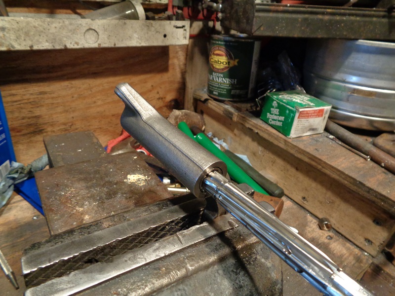
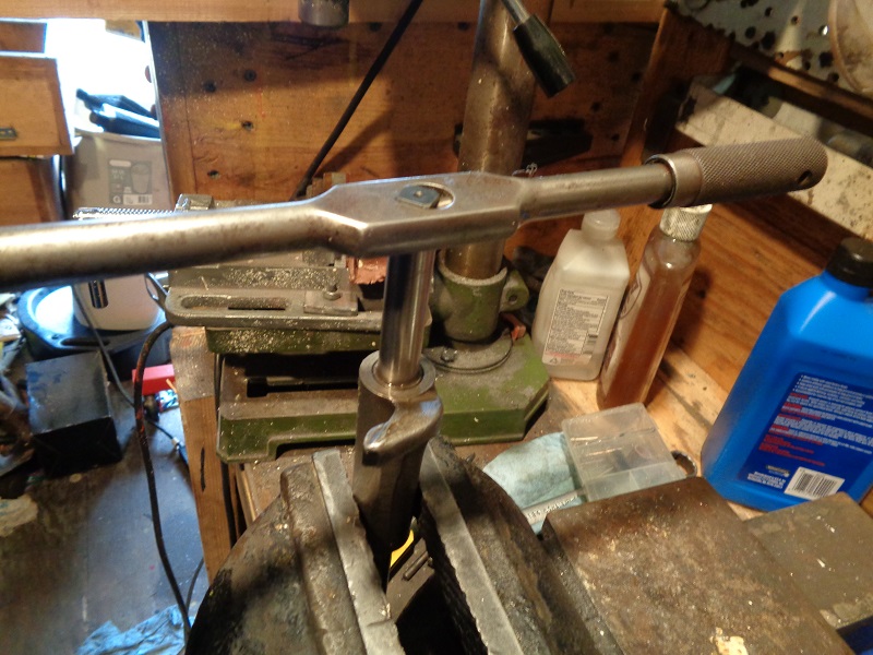
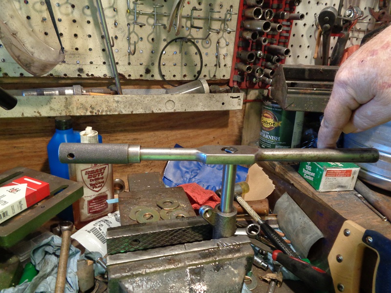
- The Jims reamer (94804-57) was used to run through the loose side to square up the hole for reaming on the other.
A 12-point 12 mm socket was used as a finger hold to turn the reamer in by hand.
(turning slowly by hand to let the reamer do the cutting) - Continue until the reamer makes it to the end and push it out.
- Then clean the shavings and run it back thru to make sure you got a uniform cut.
 |  |  |
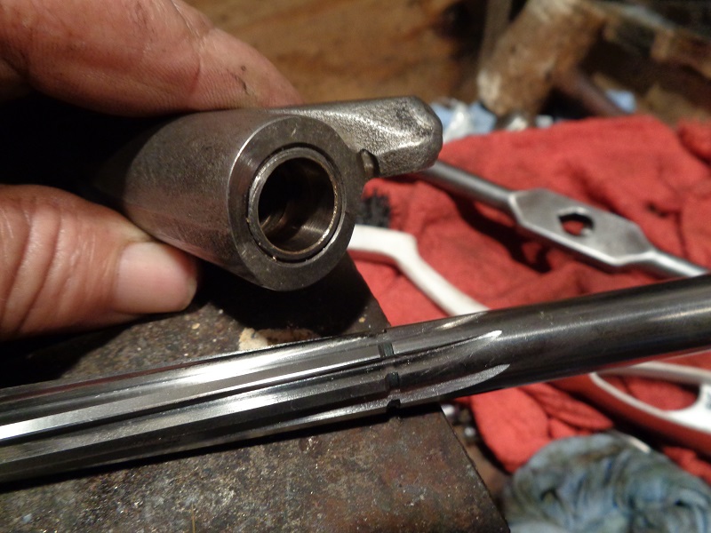
- When done, the shaft slid into both ends evenly with no slack.
The smaller bore mic'd out to .555“ which is the same as the other side now. - At ambient temperature of 54°F, the shafts would not slide out on their own with the rocker box turned vertical.
 |  |
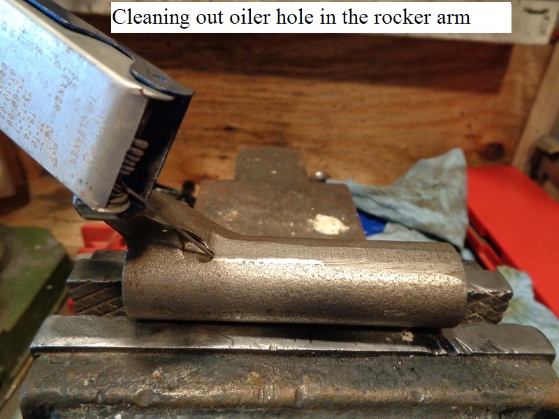
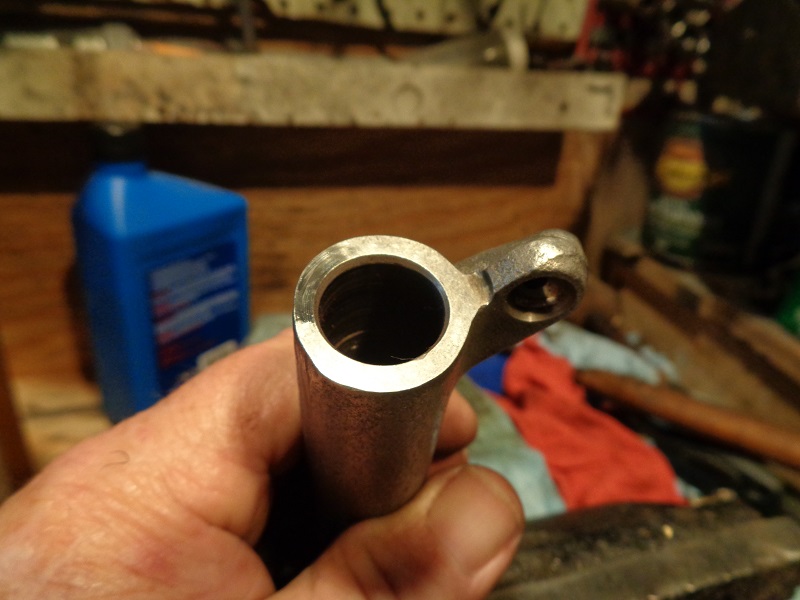
Check the valve oiler hole in the rocker arm
The valve side arm has one tiny little hole that the intake rockers don't have. 47)
This tiny little hole is for extra oiling for cooling the valve(s).
While you have the rocker arms out,
You can use a welding tip cleaner or other small wire to poke down this hole to clean or verify the hole is clear.
Visual Inpections
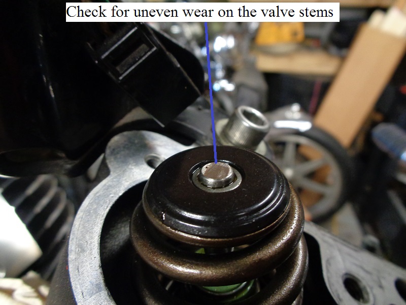
Inspect the valve stems
- Look at the condition of the valve stems in the heads.
This will give you an indication of how the rocker pad is wearing against the valves.
Check for pitting or uneven wear.
 |
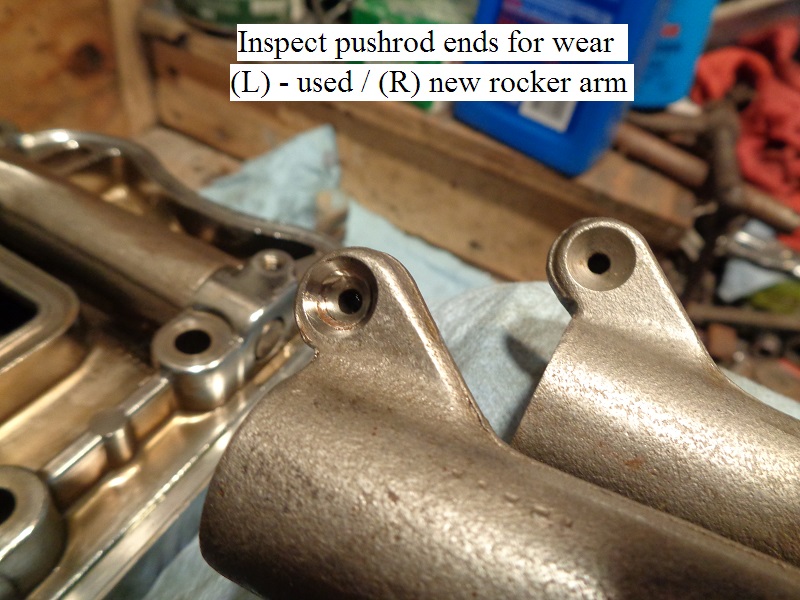
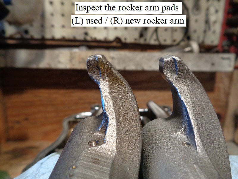
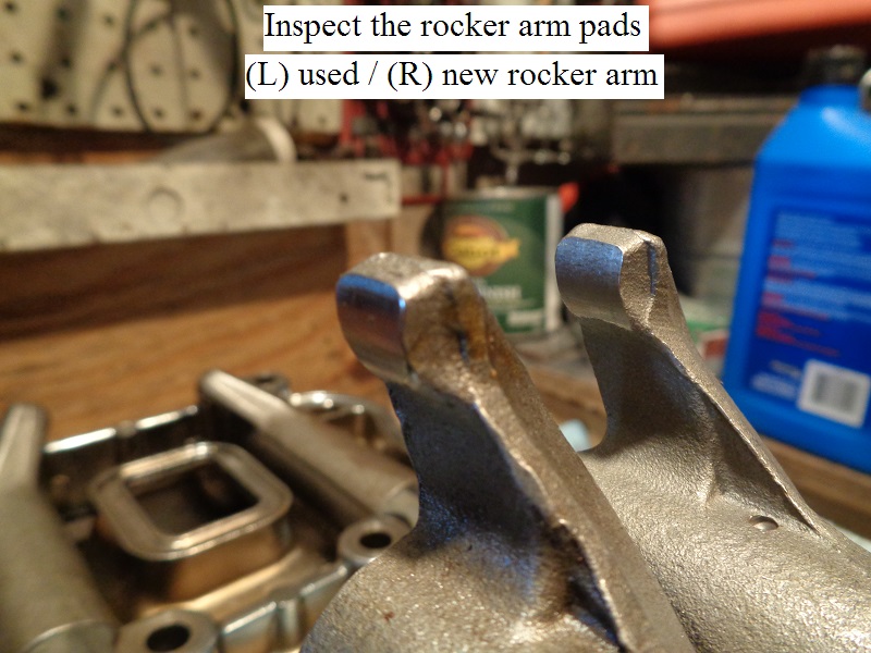
Inspect the rocker arm ends
- Inspect both the rocker arm pad and pushrod end for uneven wear or pitting.
Replace the rocker arm if either exist.
 |  |  |
Rocker Arm Bushing Replacement
Note: The bushing reamer (94804-57) has right hand blades. Always turn it to the right (clockwise) when installing, reaming or removing it from the bushings.
A helpful suggestion is to mic the bushings closely and several times to be sure you need to before replacing them. 50)
If the rocker arm pads or the pushrod cups are worn badly, it'd probably be best to just replace the arms instead.
New rocker arms come with the bushings installed and sized.
Specs: Shaft in bushing (loose)
New install: .0005” - .0020“ (.013 mm - .051 mm)
Service Limit: .0035” (.089 mm)
It's not common to have to replace the rocker arm bushings. 51)
Unless you run them dry or put high lift cams in causing them to hit the boxes, you shouldn't have an issue with them.
The bushings may wear eventually, but that should be well in to the 100k territory.
I don't know anyone who has worn one out.
As far as rocker arm bushings, where they're made isn't nearly as important as having them installed and fitted correctly. 52)
Replace the rocker arm bushings one at a time.
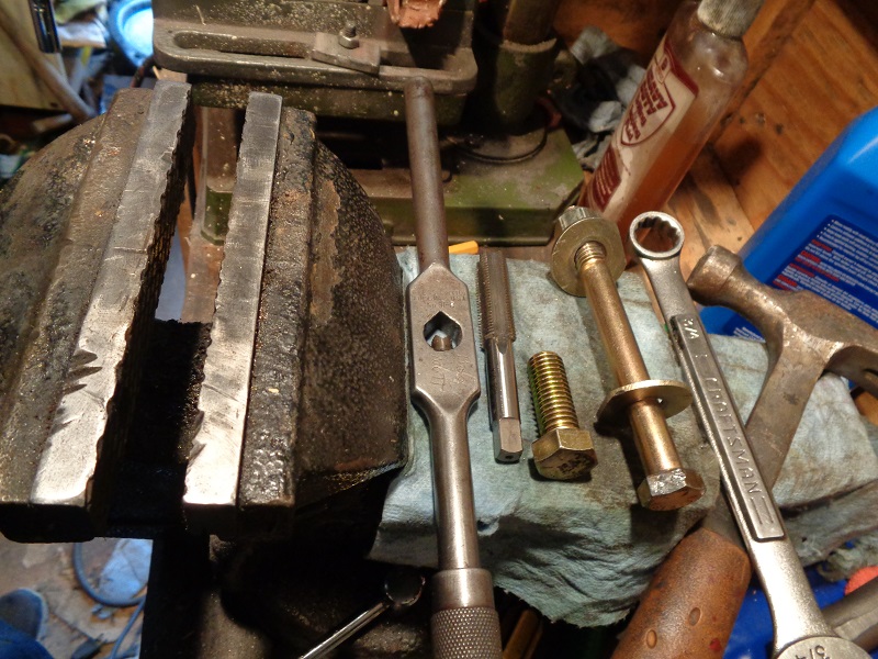
Tools
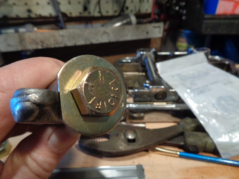
- (1) 9/16”x18 tapered thread tap
- (1) 9/16“x18x1” grade 8 bolt (3/4“ to 1-1/2” length will work)
- (1) tap wrench to fit the 9/16“ tap
- (1) drift or punch
- (1) Hammer
- (1) 1/2”x13x5“ grade 8 bolt
- (2) 1/2” grade 8 washers
- (1) 1/2“ grade 8 nut
- (1) 3/4” box end wrench
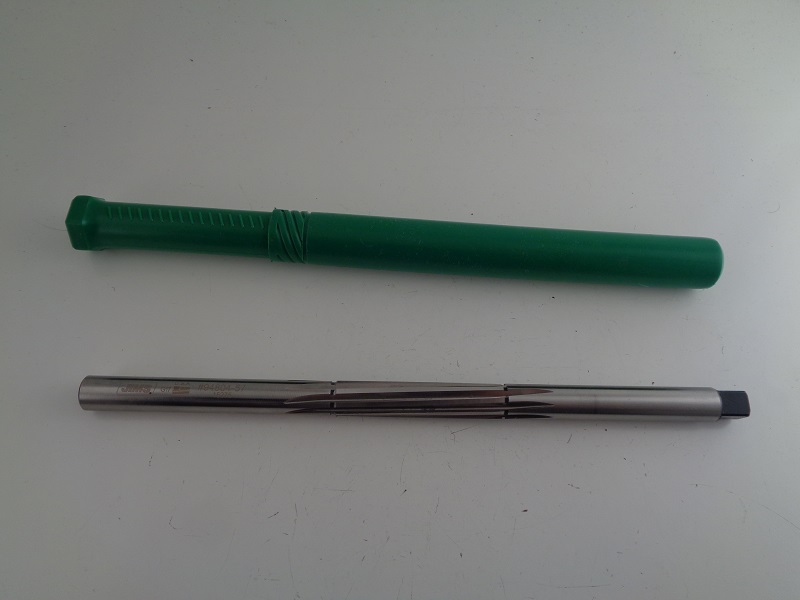
- Rocker arm bushing reamer (94804-57)
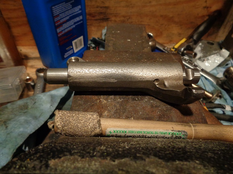
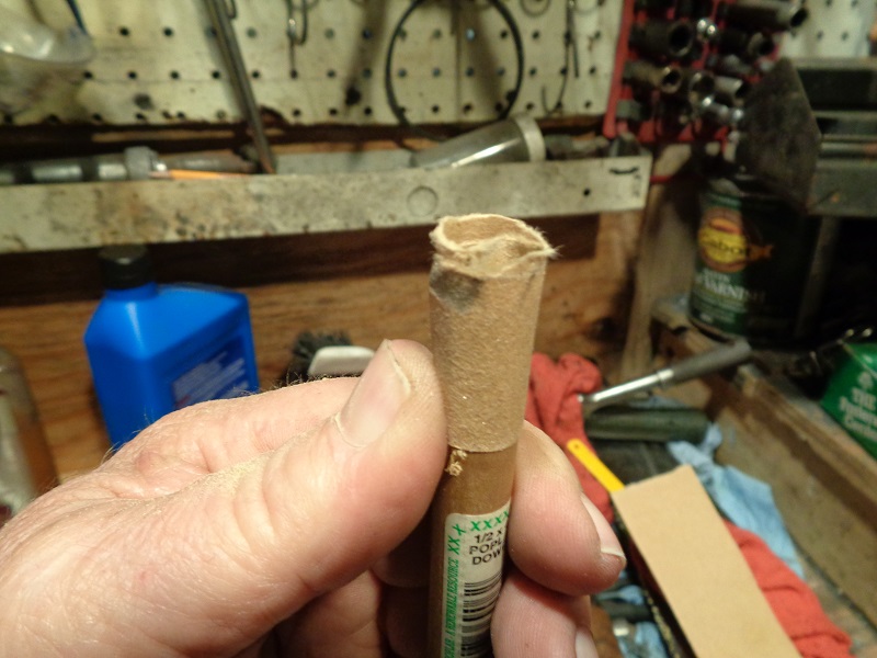
- (1) 1/2“x12” wooden dowel
- A few small pieces of sandpaper:
- 60 grit, 220 grit, 400 grit, 1500 would be good to have on hand depending on how the reaming goes.
Procedure
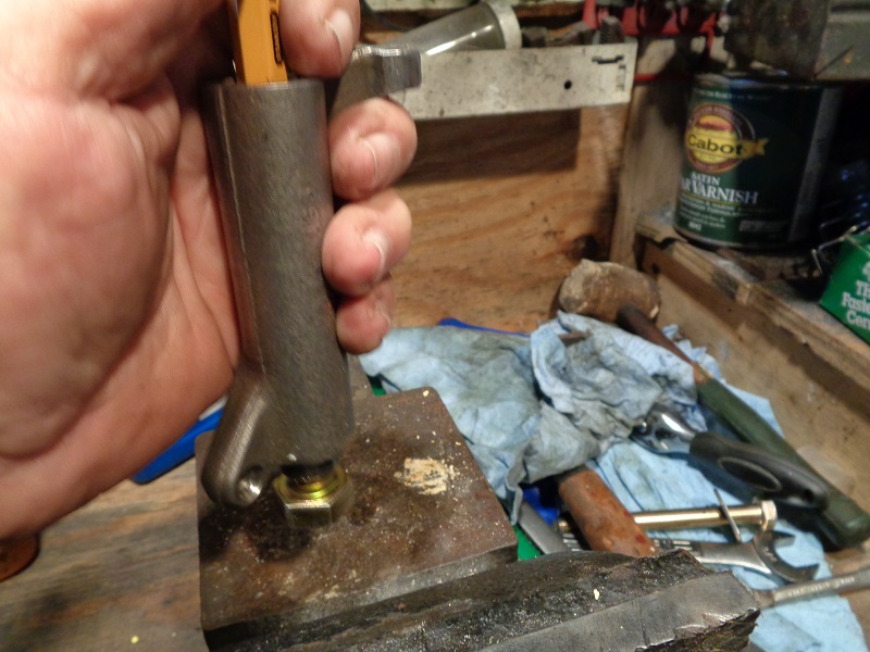
Remove the existing bushing
- Press or drive one bushing out of the rocker arm while leaving the other in place.
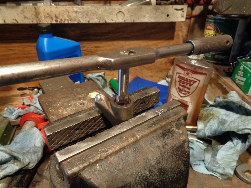
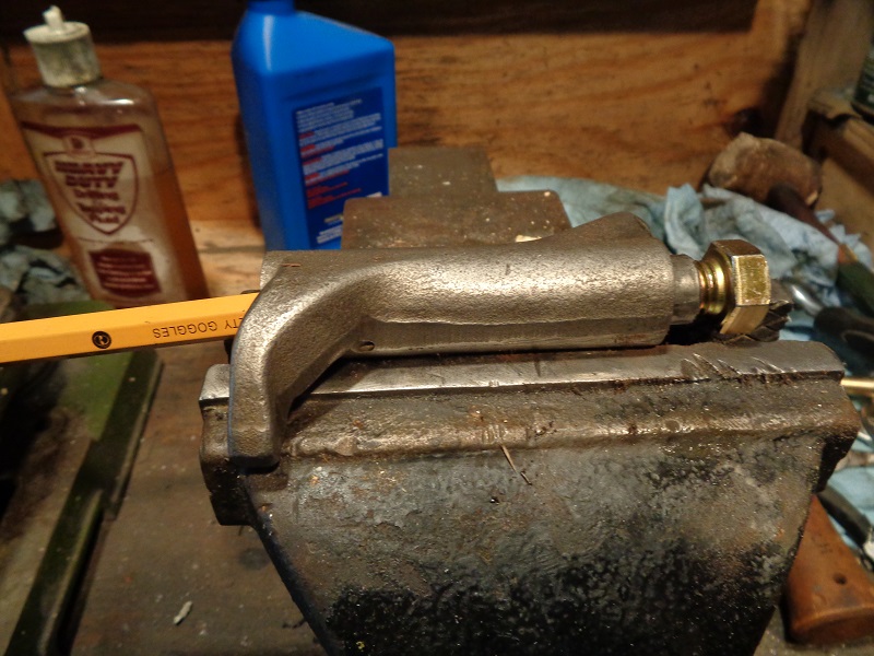
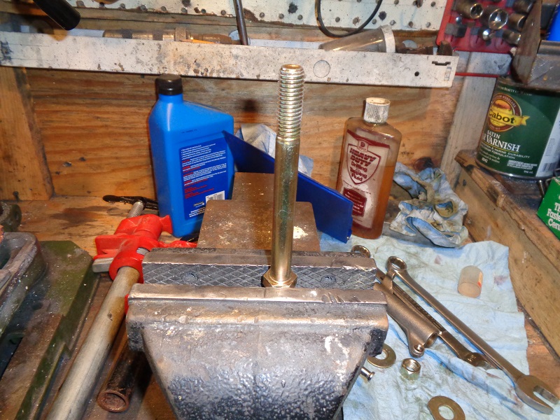
- The 9/16“x18 tap is used to cut threads into the bushing to give you something to bite into it and knock or press it out from inside out.
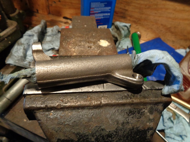
- Stand the rocker arm into a bench vise while just snugging the vise around the arm.
- The vise won't hurt the hardened rocker arm.
- Spread some tapping oil on the 9/16”x18 tap.
- Thread the tap into the bushing.
- The taper will allow you to center up the tap as best as possible before cutting the threads in the bushing.
- The bushing will be 'out of round' by default of needing to be replaced.
- Likewise, the threads you'll be cutting into the bushing will not be perfect.
- As long as the bushing will take threads, this will work.
- While tapping the bushing, hold slight pressure downward (or inward) to keep the tap from sitting and spinning.
- If it spins without continued cutting, it will remove the threads it just cut.
(if this happens too far into the bushing, the new threads will be useless in removing the bushing) - Thread the tap in far enough to cut threads on the full length of the bushing.
- The tap won't be long enough to affect the existing bushing in the other end.
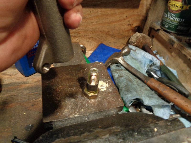
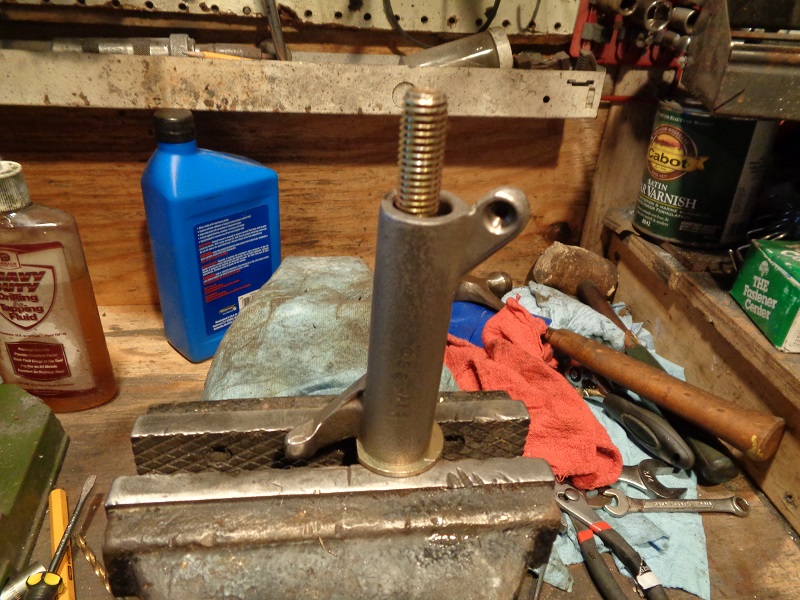
- Remove the tap, clean the new bushing threads and install the 9/16“x18 bolt for the length of the bushing.
- The bolt is used in place of the tap to keep from damaging the tap while knocking the bushing out.
(the bushing can also be pressed out using a drift on the bolt as well)
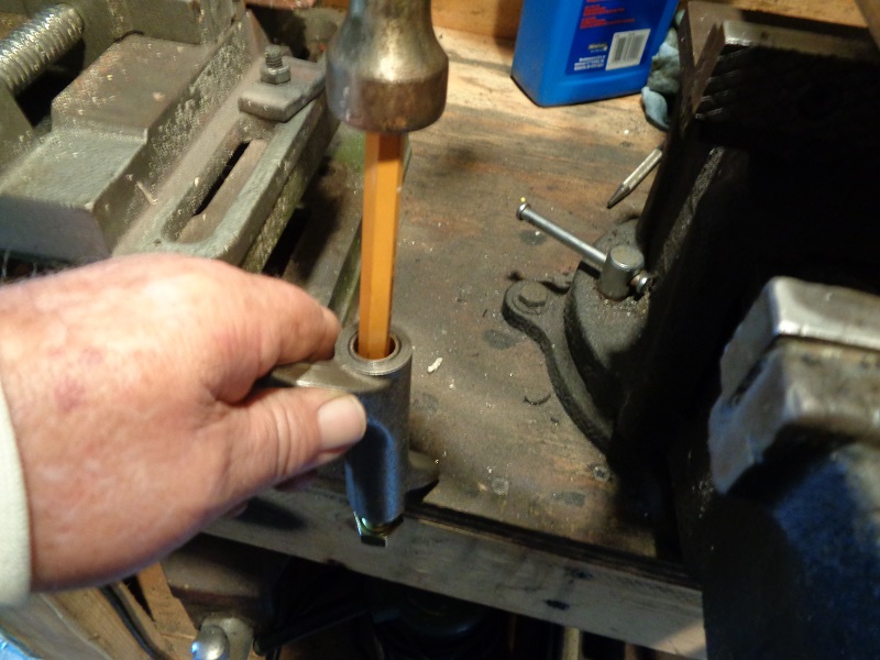
- Then, from the opposite end, press or knock the bushing out of the rocker arm using a drift or punch.
- The rocker's arm can be set on a wooden corner with the shaft bore hanging off the edge.
- Then place the drift into the opposite end and hit downward with a hammer.
- It takes a couple good strikes to knock the bushing out about halfway.
- Then you can hold the assembly in one hand and gently finish tapping the bushing out.
| Thread the lubed tap into the bushing. 56) | ||
 |  | 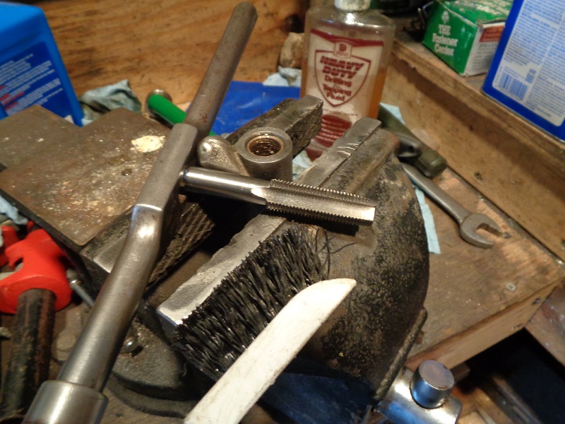 |
| Clean the threads in the bushing for the 9/16” bolt. The vise won't hurt the rocker arm. 57) | ||
 |  |  |
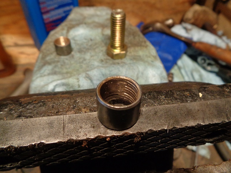
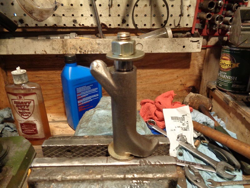
| Run the 9/16“ bolt in for the length of the bushing. It takes a couple good hits to initially move the bushing. 58) | ||
 |  |  |
| Once the bushing pops out about halfway, you can use softer blows to finish removing the bushing (and not drop and ruin the bolt threads). 59) | ||
 |  |  |
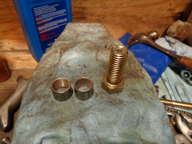
| The newly cut threads will be damaged once the bushing is removed. This makes the initial threading important for best results. 60) | ||
 |  |  |
Install the New Bushing
- Press the replacement bushing into the rocker arm flush with the arm end.
- Place the split portion of the bushing towards the top of the arm.
- The 1/2”x13x5“ bolt was used below to pull the new bushing into the rocker arm bore.
| Clean the bore of all oil and debris. Actetone or brake cleaner works well. 61) | |
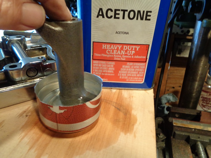 |  |
| Standard 1/2” washers were cut down on one side to clear the rising edges of the arms to get a flat pull on the bushing. Then the bolt hex was stood up into a bench vise. 62) |
||
 |  |  |
| One modified washer, then the rocker installed over the bolt. Adjust the washer to fit around the arm. Then add the bushing, second washer and nut. Make sure the split in the washer is facing up as in the installed position. At this point, it doesn't matter about the position of the notch made in the second washer. |
||
 |  |  |
| Turn the bolt in with the wrench in one hand and the other hand on the rocker (as you would with a torque wrench). This will help keep the turning force centered and keep the rocker arm from moving in the vise. When you've gotten down to the rocker arm with the washer, loosen the nut and reposition it around the arm and snug the nut back down. This will help give an even pull on the bushing when you get that low. |
||
 |  |  |
| When the nut bottoms out, remove it and the washer to check that the bushing is flush with the arm end. If not, you can try the old bushing as a spacer but with it being split, it's a one trick pony then the sides push wider than the new bushing. Test fit the arm into the rocker box to see if it will bind up while installing it. |
||
 |  |  |
| If so, the bushing isn't home yet. The nut below was installed alone to pull the bushing in the rest of the way. The washer apparently bowed in the middle close to the end and wouldn't finish pulling in the bushing. Test fit the arm once more to make sure it will reside in the rocker without binding when turning side to side. | Look for protruding burrs on the end of the bushing. | |
 |  |  |
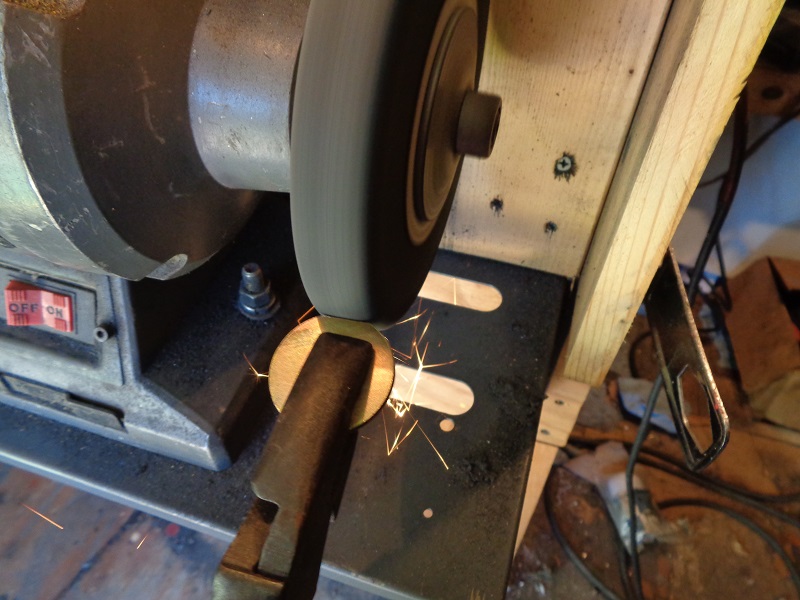
| If needed, the end of the bushing can be filed down flush to the rocker arm. Place a straightedge across the assembly to ensure it's flat end to end. The file will cut down the bushing before harming the hardened rocker arm. 63) |
||
 |  |  |
Ream and Lap the New Bushing
The proper way to ream rocker shaft bushing's is to come in from the opposite bushing with the reamer. 64)
That way the existing bushing acts as a guide for the bushing being reamed.
Factors for a good reaming job include; 65) 66)
- Alignment: The bushing needs to be in perfect alignment when pulled into the rocker arm.
You'll also be using a wider bore (existing used bushing)than the reamer as a base line.
Choose the best bushing of the two to replace last.
The reason for line boring is to get a straight line thru for the shaft.
What is bad about a reamer and going free hand is bell mouth. 67) Slight wiggles can create a wider opening on the outside of the bushing.
Using the existing bushing thru to the new one 'helps' to keep the reamer centered in the rocker arm. - Size: You have little, if any, control over the finished size the reamer gives while doing this at home.
You basically get what the reamer gives. Finished over size or under size is not a good thing.
Sizing needs to be done to fit each rocker shaft to it's corresponding bushing. I.E. A to A, B to B, etc. along with trial fitting with zero burrs or high spots on the shafts. 68) - Position: Each bushing should be installed straight, not cocked or collapsed. 69)
If the new bushing installs at a slight angle, this will throw the position of the reamer off.
Then the reamer will have to cut at the same time it's fighting a non straight path toward the end of the bushing.
The bushing will shrink when it is squeezed into the arm bore.
The slit in the bushing may also distort to an 'out of round' condition when installed creating a bumping condition while reaming. - Surface finish. Again you have little, if any, control over this at home. You basically get what the reamer gives. Too course isn't good for bushing life.
- Machining conventions. This is the method for replacing the bushings in the rocker arm as explained in the FSM.
The process is slow, not to mention the variances in accuracy.
Chances are the MoCo used dedicated machinery to handle this task.
This method is an answer to a field tech or home mechanic needing to change the bushings.
Chances are the results will not be as good as the factory machining hence the wide spec range for a new installed bushing job.
The process;
- Line ream the bushing using rocker arm bushing reamer (94804-57).
- “Jims” also makes this tool. You can find it online.
- Use the remaining old bushing as a pilot hole (to keep center).
Reaming
| Keep plenty of cutting oil or lube on the reamer. 70) |
 |
| A 12 mm socket and wrench can be used to turn the reamer. But a standard tap wrench works good. You can see how much was cut out during reaming. 71) | ||
 |  |  |
| The reamer was sent back through with resistance noticed. But no more shavings ended up on the reamer. So the reamer is done cutting even though the shaft will not slide into the bushing and probably from one or more conditions above. The reamer theoretically cuts a center hole thru / from both bushings. However, the hole now has to be lapped to widen the 'centered' hole to accept the shaft. (in proper clearance) 72) |
||
 |  |  |
| You can see beginning reamer cut in the first pic below. As the reamer came thru, it didn't cut in the middle as well as it did in the beginning. This left an app .0003“ hump in the middle of the bushing. Some of that came out with a short lapping with 220 grit. |
||
 |  |  |
| The reamer was lightly ran back through. | This revealed a dark ring where the reamer was binding but not cutting. | |
 |  |  |
| The shaft did slide in with light resistance but repeated turns with the reamer also created heat in this spot. It still needed to be lapped for greater clearance. | ||
 |  |  |
| The high spot was taken out after lapping. |
 |
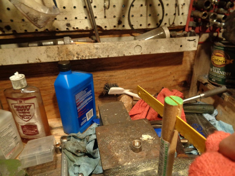
Line Lapping
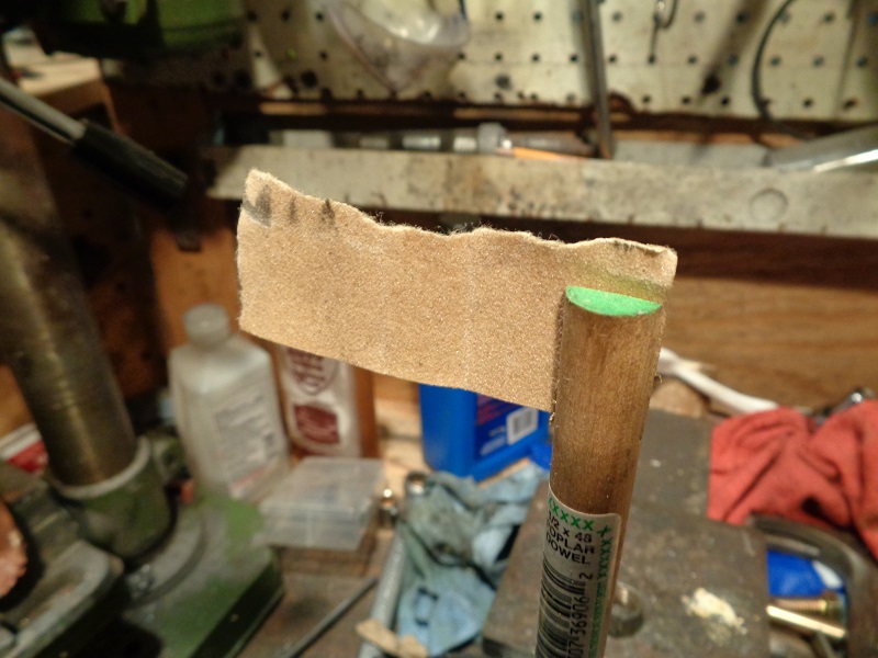
A lapping tool can be made from a 1/2” wooden dowel and a small piece of sandpaper. 73)
Make the dowel long enough to run the full length of the rocker arm plus enough to get a hand on to turn it (12“ or so).
Use a hacksaw blade cut a slot down the middle of one end to hold the sandpaper.
Make the slot longer than the bushing so you can be sure to have contact on the full length of the bushing.
 |  |
Initially cut a piece of sandpaper to go one full revolution around the dowel. 74)
Too many wraps will not slide into the bushing as it will then be too thick.
You can add more if needed but be sure and measure the bore periodically so it doesn't get out of clearance.
You just need to turn or lap the bushing slowly and evenly.
This will also smooth out the bushing surface for a less restriction on the shaft.
Grit of sandpaper will be determined by the condition of the bore and clearance desired.
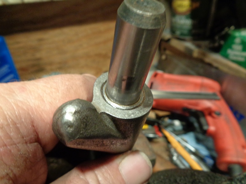
Insert the bare end of the dowel into the bushing to lap and exit the dowel out the non lapped bushing.
This will allow you to basically line lap the intended bushing to help keep center between the two.
| 60 grit was used first for a couple rounds followed by 220 grit paper (re-measuring before each new piece was used).75) | ||
 |  |  |
| Line lap, measure and check shaft fit and movability. Each time you remove the lapping tool, spin it out while pushing on it. This will help keep from creating an axial scratch in the bushing. 76) |
||
 |  |  |
Repeat until the clearance is correct at each bushing / shaft end (individually measured and matched per side).
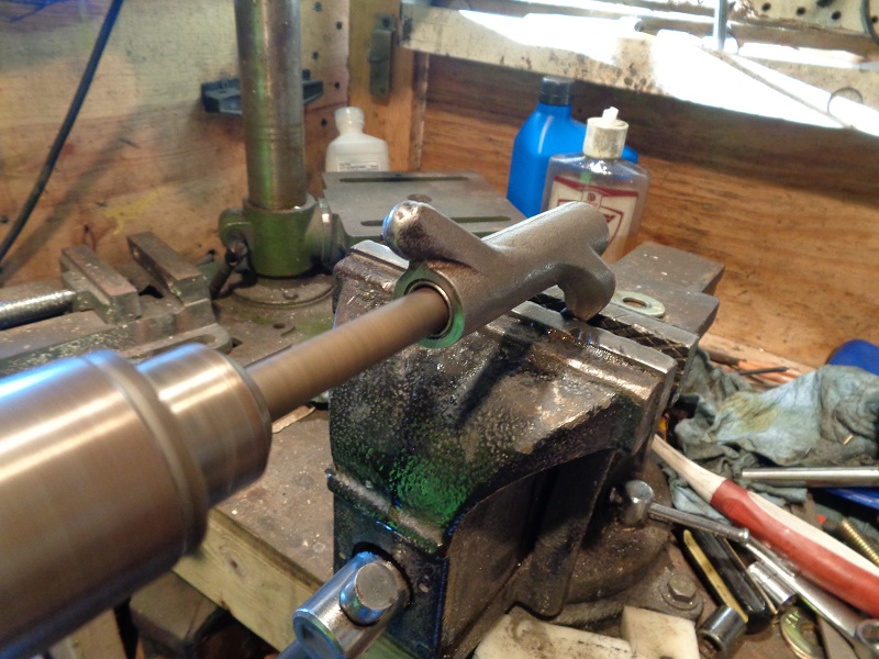
| A drill with fine sandpaper can also condition for a slick surface. Test fit with the assembly in the rocker. 77) | |
 |  |
Repeat for the other bushing(s)
- Once you've got the new bushing reamed and lapped, repeat the procedure for the bushing on the other end.
- This time, you'll use the new (sized) bushing as a pilot hole to ream the second bushing.
Stabilizing Noisy Rocker Arm Shafts
As for the ticking / tapping noise mentioned above, some people rather like the noise and others don't.
You can inspect the shafts during operation to see if this is happening to your shafts.
Remove the top (and middle if applicable) rocker box cover.
Clean the area around the shaft ends and lower rocker box on one side of the cylinder.
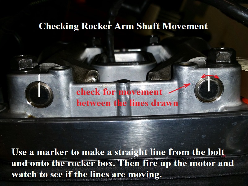
Draw a straight line with a marker across the shaft end and onto the rocker box.
Start the engine and watch the area of the line between the shaft and rocker box.
If the shaft is turning, you'll see back and forth movement of the straight line on the shaft.
| Checking rocker arm shaft movement 78) |
 |
At this LINK there are two videos.
The first one has a before and after, beginning at about the 2 minute mark.
The second one has a before right at the beginning of the video.
The shafts have a notch in them that the bolt is supposed to butt up against which locks the rocker arm shafts in place.
However, the bolt hole is too large which leaves a gap there.
This gap allows the shaft to slightly rotate and hit the bolt which causes an annoying ticking / tapping noise.

Aftermarket rocker bolt spacers are made to close the gap between the bolts and the shafts.
It's important to note that no engine needs these. 81)
There is nothing detrimental to the engine when it is ticking because of the rocker shafts banging into the bolts.
The only reason they would be “needed” is if the ticking bothers the owner of the bike.
Two bushings, or spacers, are used for each rocker box.
They are installed into the rocker box to head mounting holes on the pushrod side next to the rocker arms.
There are no provisions from the MoCo for this gap to be used for oiling or to control heat.
It's a closed gap inside the lower rocker arm bore.
Oiling and heat control is handled through the clearance between the shaft and the arm bushings.
And also through a hole in the (exhaust only) rocker arm shaft on the exhaust side behind the shaft bushing.
The issue of the noise could be easily fixed at the factory with shoulder bolts. 82)
In fact, each of us could fix it with shoulder bolts. But those are more costly than the bolt spacers.
Experiments were done with bolts that had larger (precisely machined) shoulders.
These kept the rocker shafts from clanking back and forth against the bolts.
However, there were two issues:
- The precision shouldered bolts are more expensive to machine than the bolt spacers.
- In very much of what HD does, they use very loose tolerances.
Not because they are needed, simply because it is easier and less expensive.
This is not just in the engine, but on the frame also.
Most of the time when using the machined bolts (instead of rocker bolt spacers) everything worked fine. 83)
However, a small percentage of the time, when there was not any play between the diameter of the bolt and the diameter of the bolt hole,
We were unable to get the rocker box sitting exactly where it should.
The rocker bolt spacers take into account the cascading effect of loose HD tolerances.
Rocker Lockers
Rocker Lockers eliminate the gap between the rocker mounting bolt and the slot in the rocker arm shaft.
They are available at DKCustoms
This locks the shaft from turning and striking the bolt and eliminates the ticking noise.
They also center the rocker plate so that it is always located in the same position.
This helps to eliminate different wear patterns on the rocker arm/valve and a better alignment of the pushrod in the holes.
The Rocker Lockers are tapered so that they lock themselves in and wedge the bolt/shaft in place.
Note:
Rocker Lockers will not quiet noisy lifters, noisy chains, gears, tensioners or bearings.
If you ever need to remove the lockers, just use a punch and tap them out, they are usually reusable.
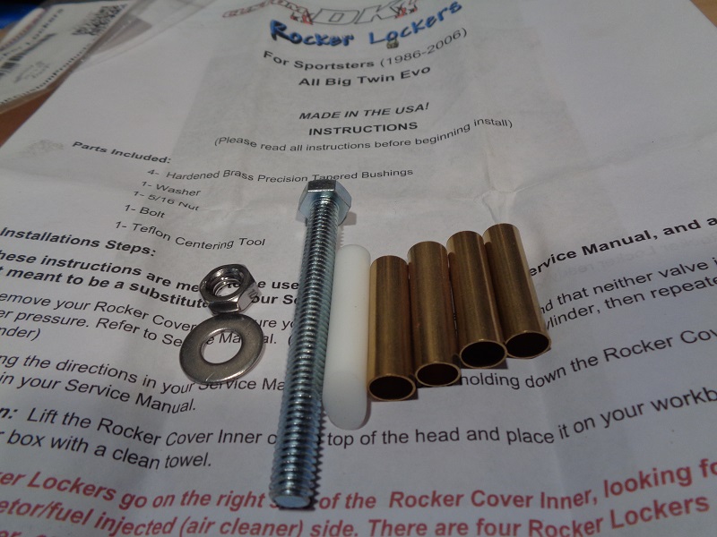
- The 86-06 Sportster kit includes: 84)
- (4) Brass tapered bushings
- (1) Bolt, Washer & Nut for installation
- (1) Teflon centering tool
- Step-by-step installation instructions
- The 07 and Up Sportster kit includes: 86)
- (4) Brass tapered bushings
- (1) Washer & Nut for installation
- (1) Teflon centering tool
- Step-by-step installation instructions
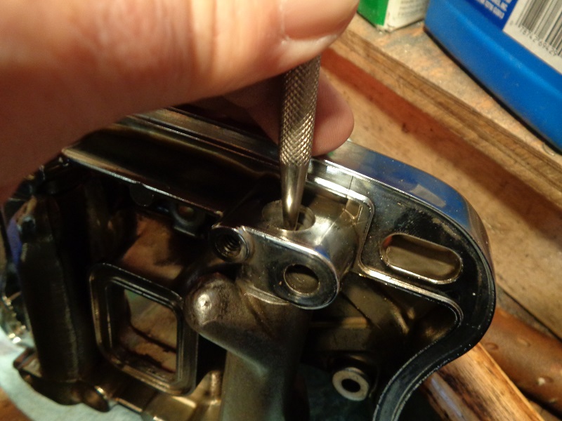
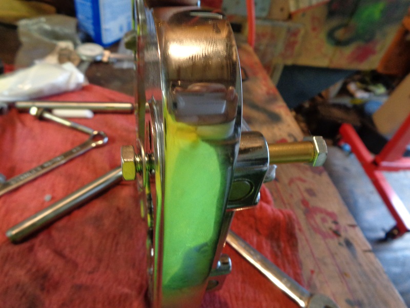
Using the Teflon Installation Tool
- Use the Teflon tool supplied with the kit to vertically center and align the slot in the shaft.
- The tool will straighten it on the way out the bottom.
- The shaft would need to be able to spin by itself inside the bore while pushing the tool in so the tool could align the slot.
 |  |
 |  |
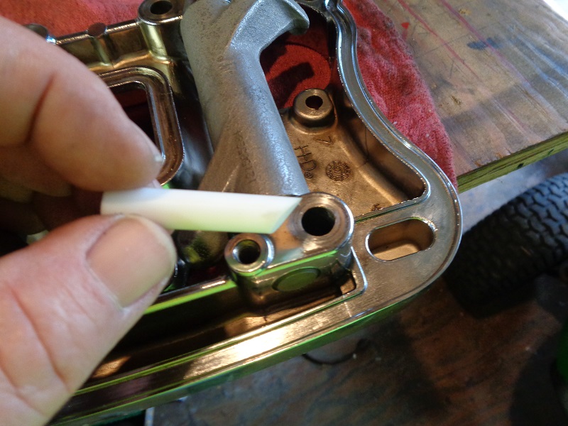
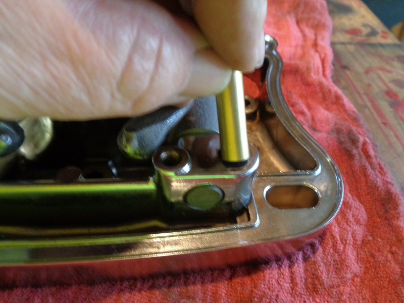
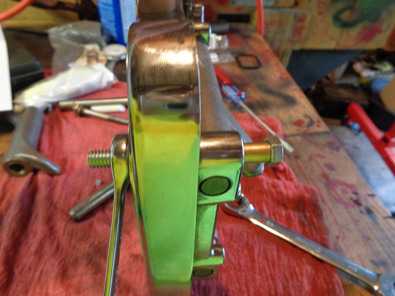
Installing the 86-06 Kit
- The tapered end of each bushing goes in first.
- The tapered side is fairly easy to find.
- The wider end will not go into the hole.
- And the tapered end easily slips into the hole with a light pressure applied.
- The non-tapered end won't go in the hole. 87)
 | 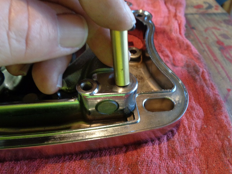 |  |
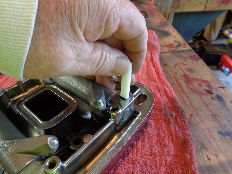
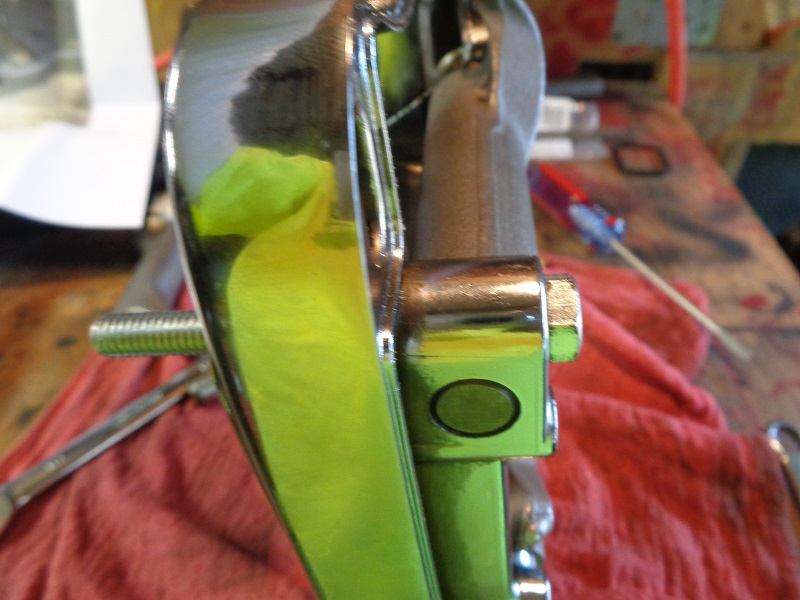
- Then the bolt is installed in the top with the washer and nut on the bottom.
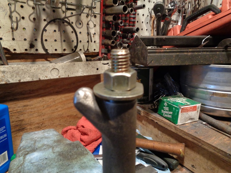
- Tighten the nut / bolt until the bushing pulls in flush at the top.
- It should pull in with minimum force applied. then remove the installation bolt.
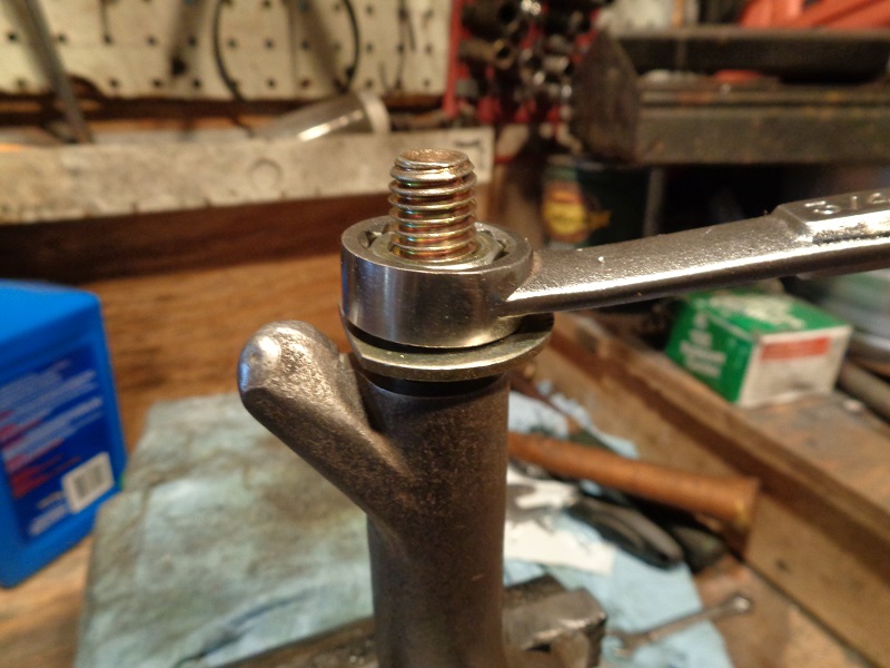
- If you turn the nut and hold the bolt end still, this will pull the bushing in instead of turning it into the hole. 88)
 |  |
 |  |  |
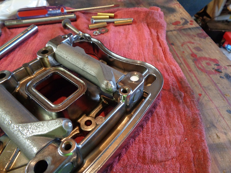
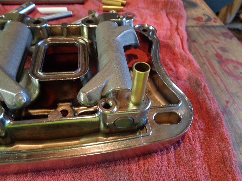
- Check fitment of the regular rocker box mounting bolt to ensure it goes into the bushing and rotates freely.
- Then repeat for the other side.
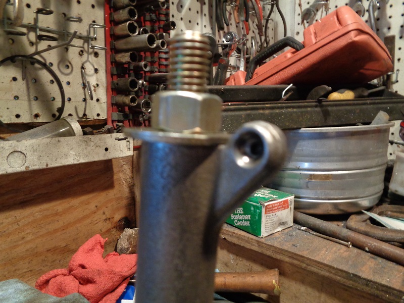
- Inspect and make sure you can't see the shaft through the hole.
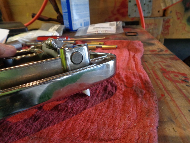
- Insert the Teflon tool for verification of shaft alignment. 89)
 |  |  |
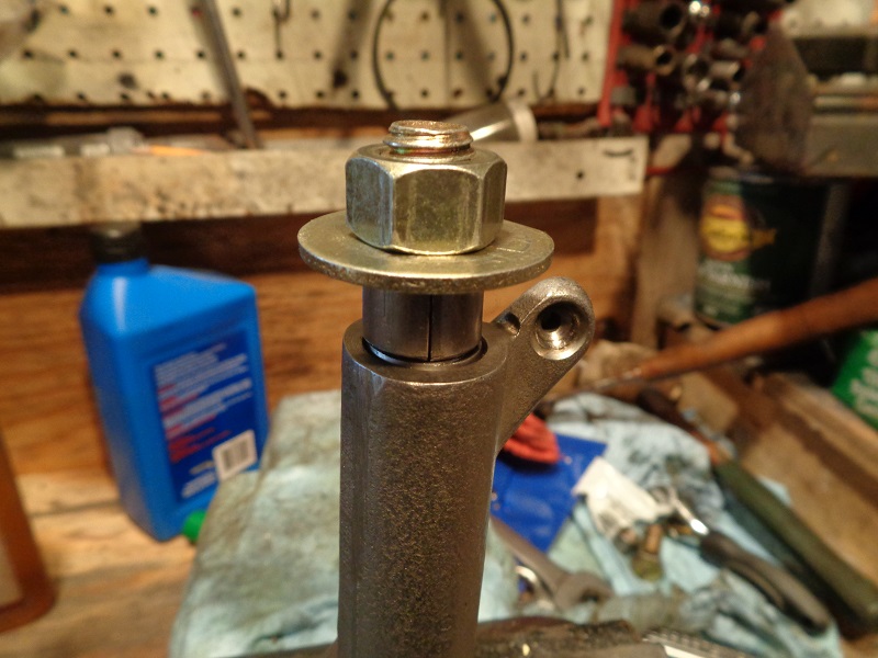
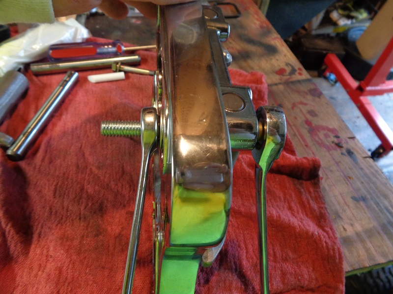
- Then pull the bushing in with the installation bolt.
- Now you have both Rocker Lockers installed and ready to bolt back to the heads. 90)
 |  |  |
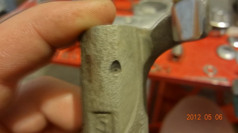
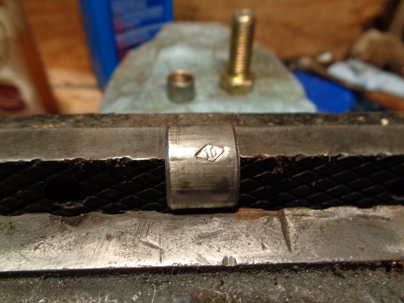
ROCKOUT Rocker Shaft Inserts
ROCKOUTs also eliminate the gap between the rocker mounting bolt and the slot in the rocker arm shaft.
They are available on Amazon, Ebay, and directly from Rockout.biz
Installation instructions are also online at Rockout.biz
The rocking / sliding action of the loose shafts hit the bolts so hard it can leave dents in the shafts. 91)