Table of Contents

REF: Engine Mechanicals - Sub-09N
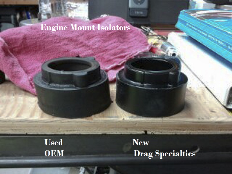
Isolator Inspection and Replacement
Having to replace bushings and bearings related to motorcycle suspension has been a normal maintenance routine since the beginning of time.
There seems to be a wide variety of mileages where the swing arm bearings and rubber mounts need replacing.
Keep in mind the rubber mount design also has 3 stabilizer links that connect the engine to frame and allow vertical movement from engine vibration.
They also maintain side to side alignment of the engine and frame. Make sure they are tight.
In addition, there is a pivot shaft that supports the swing arm bearings / bolts on the outside, and goes through the rear mounting lug on the tranny case.
If the pivot shaft is loose in the rear mount lug, it will need to be replaced also.
Lube and properly tightening steering head bearings are also important part of the process. 1)
You can raise the bike on a jack and see engine swing better when pushed than while sitting on the tires.
One option instead of replacing the mounts is loosen all the mounts up slightly, run the motor for a moment then go back around and re-torque them. 2)
Replacement Rubber Options
You can use a couple small automotive scissor jacks, one towards the front and one towards the rear, to support the weight of the motor and give some flexibility in moving it around to line things up. 3)
The manual says they need to be inspected every 10k, but if you're running the OEM rubbers, you can pretty much plan on replacing them at about 30k, ish. Some have replaced them after 10k. Others reported 50k to over 100k and no problems.
- OEM mounts:
If you don't want more vibration, use the H-D mounts, but plan on replacing much more often. 4)
They seem to be soft and to not last. There may be a lot of sportsters with softened or sagging mounts that need replacement. 5)- Front Motor Mount Isolator (2 each required): H-D 48463-04A
- Rear Motor Mount Isolator (2 each required): H-D 48492-04A
- Drag Specialties mounts:
The DS mounts seem to be slightly stiffer than the HD mounts.
Some extra vibes have been reported using the poly mounts under 2K. 6)
Handling is also reportedly improved over the OEM mounts.- Front Motor Mount Isolator (2 each required): Dennis Kirk 140553 (Drag Specialties 0933-0054)
- Front Motor Mount Isolator Kit - includes 2 isolators & new hardware: Dennis Kirk 1400195 (Drag Specialties 0933-0117)
- Rear Motor Mount Isolator (2 each required): Dennis Kirk 140554 (Drag Specialties 0933-0055)
- Rear Motor Mount Isolator Kit - includes 2 isolators & new hardware: Dennis Kirk 1400196 (Drag Specialties 0933-0118)7)
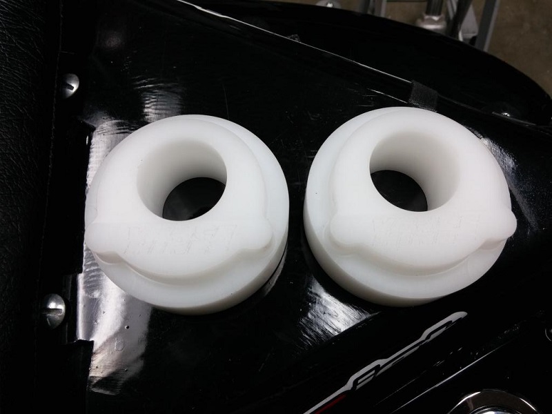
- Vance & Hines mounts:
Sold and made by Vance & Hines.
They will require you to sign a release where you agree they are for racing only, and V&H isn't liable if bad things happen.
From XLForum member, Nytstr: 8)
The bike corners like it's on rails, and the wallowing, suspension taking a 'set' is totally gone. It's like a new bike entirely.
There is increased vibration, as one would expect. But so far it is not real bad, just a buzz in the seat mainly, and certainly livable for me.
Note: Some advise against hard poly mounts for fear of cracked cases.
Polyurethane mounts are good but they do transfer vibration a lot more than typical rubber. If you replace one piece of rubber with polyurethane you need to do all of them. 9)
Polyurethane is stiffer, it will transfer some movement and vibration to the non-polyurethane mounts causing them to wear faster and have funky movement.
They will not reduce lateral play of the swingarm and will not improve handling because the rubber mounts do not control lateral play of the swing arm. 10)
Front Rubbers
Inspection
Note:
The front motor mounts are notorious for loosening up. 13) Also check the condition of all the motor mount rubber isolators, they can deteriorate from age.
If you over tighten the front mount, you're compressing the mount making it stiffer. 14) This leads to less give and a much higher chance of cracking the front mount.
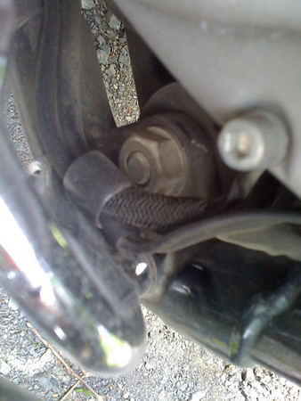
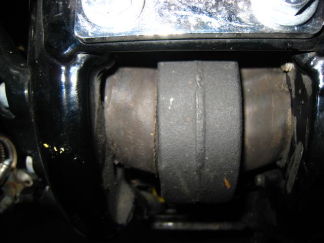
Check the large thru bolt (1“ hex head) in the front rubber motor mount. 15) It's in the front of your bike below the voltage regulator under the oil filter. 16)
There's your rubber mount with the big bolt going through it. If there is no thread showing where the nut is on the bolt, check tightness.
Threads are normally past the end of the nut ranging from 1-2 threads to 1-1/2” or so. 17) 18) So if it's flush or so you may need to retighten it or at least check it.
As long as it's up to torque (and Loctite was applied), you're good. 19) You can remove the right foot peg and rear brake pedal to gain access to the nut.
You may only need to take the bolts out of the front peg mount and rotate it out of the way to get a torque wrench on that nut. 20)
You can used an open end wrench on the bolt head also.
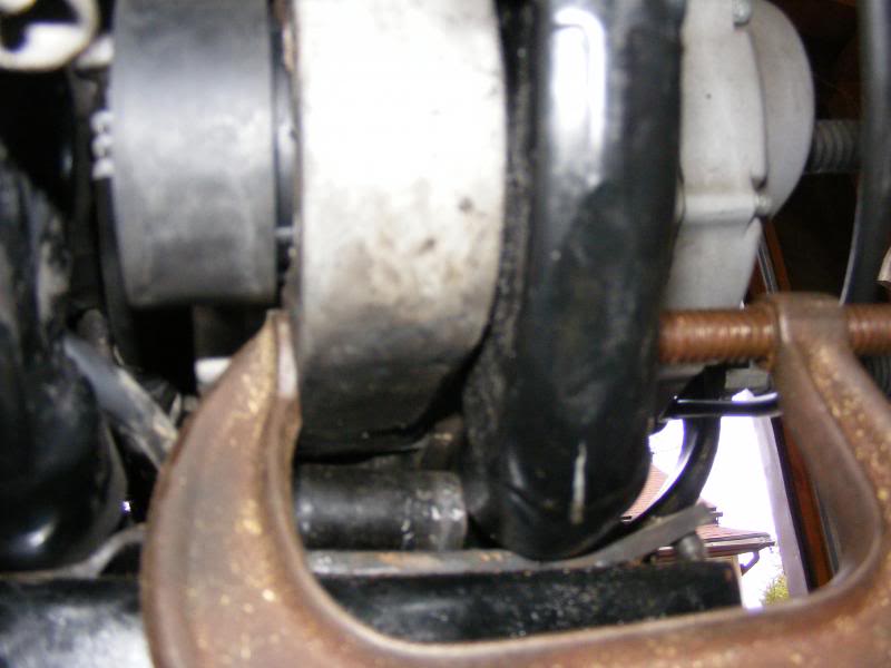
Also, when looking at the front lower motor mounts from under the bike, the rubber mounts seem to sag downward just a bit. 21)
This should be somewhat normal as the engine puts downward pressure on the mount when setting.
Both front and rear mounts can sag like this. 22)
Replacement
- The front right is a pain to pull out, you need to pry the motor an inch to the left… right up to the frame, remove the front pipe and a couple case bolts underneath. Even with the engine right up tight to the frame it is a pain to pry the old mount out. Once out, the new one slipps right in. 25)
- Use a 6“ C-clamp to pull the front of the motor right up tight against the frame. You cut the puck off the end of the threaded rod part of the clamp, and now it has a round ball on the end of that clamp. You use that round end to keep the C-clamp from sliding off the frame as you tighten it and pull the front of the engine over towards the left side of the bike (the ball on the clamp is inserted into the hole for one of the support plate's bolts). So when you get it pulled all the way over to where it contacts the frame as you mentioned, you just keep turning the clamp and somehow it pulls the rear of the engine over just enough to where the mount will fall out on it's own if it's sitting at the right angle. 26) Don't lift the front too high else it will hit the frame before it is over far enough. 27)
- Front mount- There is a “shaft” on the RIGHT mount if it (there is actually 2 “shafts”) but removing the SHAFT from the Right mount will make things easier. If you have forward controls, remove them and the above is correct remove the “dog bone” mounts it will help you “move” the motor to 1 side. If your mount is really bad out of shape it will be HARD to remove the “LEFT” mount and the right will be almost impossible… REMOVE THE SHAFT with a LONG punch then remove the rubber bushing… now you should have enough room to install the front RIGHT mount. Align it and install the left mount… reinstall the dog bones. 28)
| C-clamp for removing front right rubber. 29) |
 |
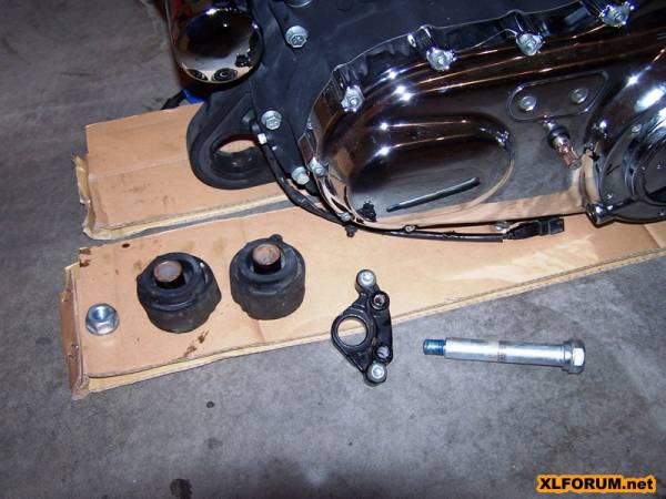
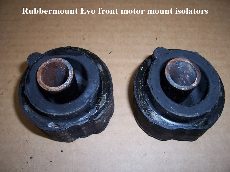
The front isolators have a little different design and basically opposite from the rear ones.
The right side slides into the frame while the left side is sandwiched by a removable bracket with two mounting bolts.
The metal tubes slide through as reinforcements for the rubber.
The isolators and the bumps on them slide into and are located within the front of the motor itself, not the frame.
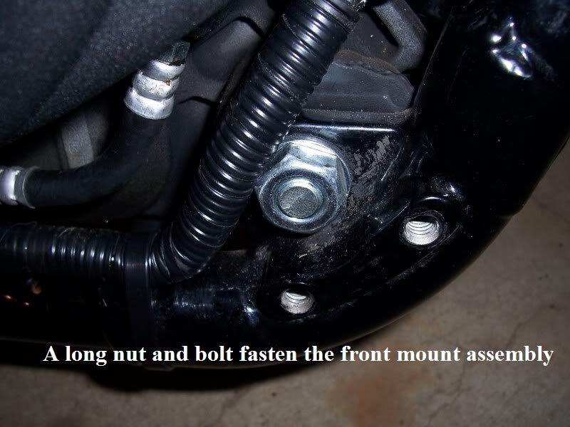
There is no pivot shaft on the front mount but rather a long bolt and nut that runs through the whole assembly.
There are metal tubes built into the isolators and the tubes are captured by the frame.
Notice in the pic below that the front rubbers have one “tab” to locate it to the frame.


Rear Rubbers
Inspection
The rubber mounts do not prevent lateral play of the swing arm and motor. 35)
The pivot shaft connects the swing arm to the rear motor/transmission mount. There should not be any lateral play there, between the swing arm and rear motor mount.
The 3 stabilizer links connect the engine to the frame. Again there should not be any lateral play there.
If any of these metal to metal connections are loose, only then will the rubber mounts have to stabilize the lateral play.
But they are not supposed to be doing that. So the actual problem is play in either the pivot shaft or stabilizer links.
You can't tell much about the rear mounts looking from the outside but when you remove the swingarm, you can see the pivot pin is not centered.
You can swap the rear rubbers left to right and the pin will be centered again. That way, the sag is 'flipped over' and the engine weight is working against it.
However, this won't work with front mounts because they are LH and RH parts.
Symptoms of swingarm problems:
- Excessive play in the rear wheel, difficulty keeping in a straight line in slow moving traffic. 36)
- Spherical Bearings having play in them 37)
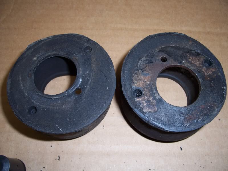
- Rear rubber mounts well out of shape. 38)
- Torx bolt head shearing off. 39)
- All of the rubber mounts are open to this problem because of the fact that the swing arm is mounted to the mount.
And it's rubber-mounted with a spherical bearing. It's got some “flex” stock most don't notice it until it's really bad! 40) - Wheel wobble has been known as one contributor from swingarm problems.
Loose / Broken Lock Plate Screws
The design issue may be that the pivot shaft is too small for the hole it goes through in the engine. It should be a tighter fit like an axle through a bearing.
The purpose of the lock plate is to keep the pivot shaft from spinning so you can tighten the swingarm bolts. It may do a fine job at that.
But, because the pivot shaft is too small, when you install the lock plate, the lock plate centers the pivot shaft in its hole.
So the engine transmits its forces not directly into the pivot shaft, but rather into the lock plate bolts, then the lock plate and finally into the pivot shaft.
Those little lock plate bolts can't handle that kind of stress so one or two of them may break.
A better fix may be a larger pivot shaft, or a shim or bushing of some sort to take up the space between the pivot shaft and its bore. 41)
A tighter pivot shift fit would help but the plate also holds against lateral shift of the shaft to the left under hard cornering loads.
The combination of that force plus wiggling of the shaft in the motor opening definitely contributes to the problem. 42)
The three screws that secure the swingarm lock plate had all worked loose on the one below and two of the heads had sheared off.
They backed out maybe some fraction of a turn until they hit the isolator.
The movement of the pivot in relation to the engine caused them to shear right below the heads of two of the three.
They are not easily seen for inspection if they become loose without a teardown as they are behind the rubber isolator when assembled.
To see them you would have to drop the swingarm.
The isolators are not holding the screws in. They are just against them (shouldn't be much pressure if any against the screws).
Most likely, only with severe deflection of that pivot pin would pressure be placed on the plate and shear the bolts.
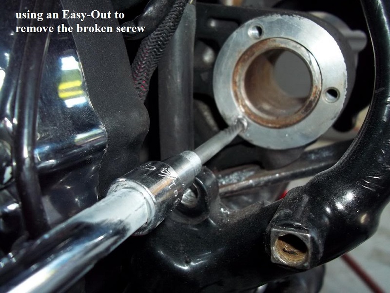
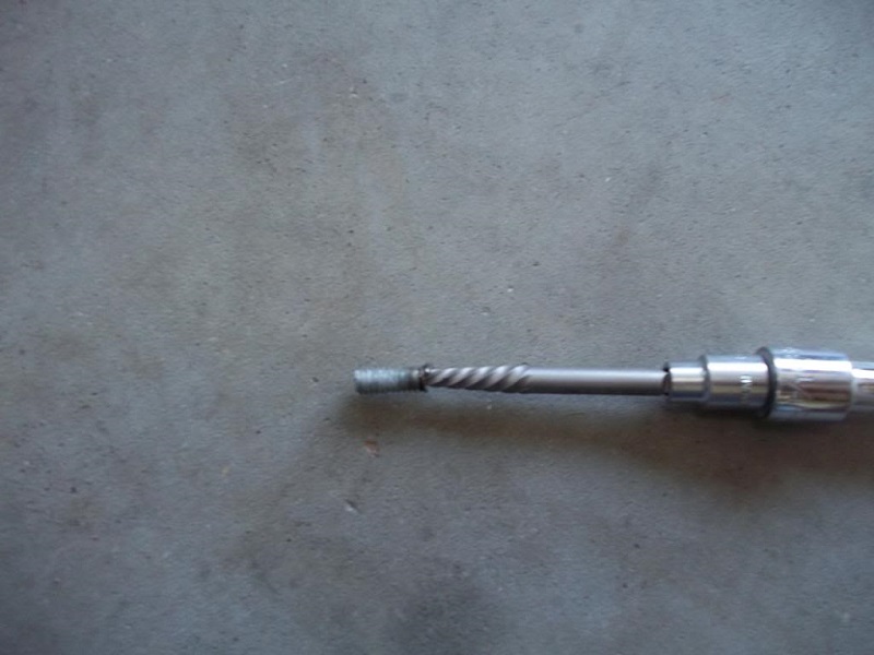
You can drill the center of the screw with a small drill bit and try and Easy-Out to remove it.


| Screw removal with Easy-Out. 45) | ||
 |  |  |
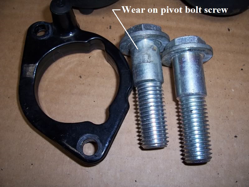
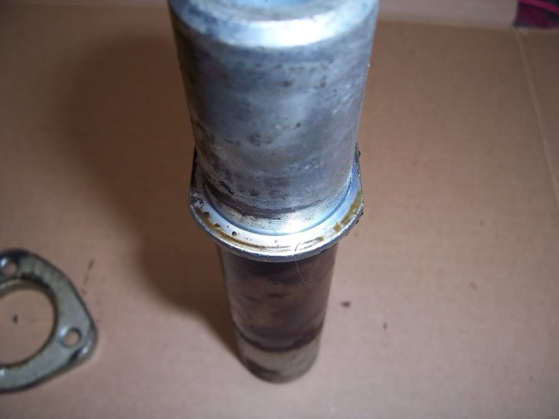
Worn / Rusty Pivot Shaft
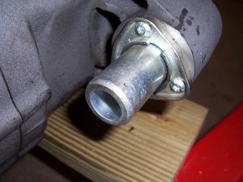
If you pull the rear mount apart, you may want to inspect the pivot shaft for wear and rust. You can pull the assembly apart at the same time you change the rear tire.
The pivot shaft has metal-to-metal contact on the shoulder where it pushes against the motor mount and all along the hole going thru the motor mount itself.
In the pics below, the groove in the pivot shaft to the right is from contact with the backing plate on the throttle side isolator.
The groove was most likely worn in by movement in the vertical axis (as the groove was on the bottom side of the shaft).
And has nothing to do with lateral play of the swing arm. 46)
Since the hole in the backing plate is larger than the pivot shaft, the backing plate is not supposed to touch the pivot shaft.
However, this may be one of the things that happens over time as the rubber gets weak and moves around a bit more.
It is an extremely tight fit going through the motor mount itself (machined shaft and mating hole).
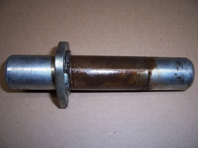
On the shaft below, there was no wear where the pivot shaft goes through the rear motor mount.
The only wear was where the isolators contact the shaft with the heaviest wear on the throttle side.
The witness mark was nearly all the way around the pivot shaft.
On the clutch side, there is a very faint mark from where the rubbermount backing plate would be hitting the bottom of the pivot shaft.
(closest to the ground where the weight would be resting on)
Dirt bike suspension bolts can be much worse. Enough wear will cause excessive play in the swing arm.
And then the rear wheel will not track straight because drive belt tension will twist the swingarm so the tire points to the left.
Water can get between the isolators and the pivot shaft and cause it to rust. 47).
The rust will only get worse as time goes by (especially if you live near the ocean). 48)
Rust can cause long term problems because it will eventually cause too much swingarm play.
Guys who live in places like Florida will have rust problems sooner than the rest of us.
You can sand blast all the rust off, use sand paper or a wire brush to remove the rust.
Then coat the shaft with a good marine water proof grease. Paint will only rust through again.

Replacement
- Remove the rear mounts and then change the fronts. Getting the right front out is easier when the tube is removed from the old mount. You can get loads of hassle getting the drag specs fronts in and having the extra movement by not having the rears in place will make it easier. Disconnect all the stabilizer links and put a jack under the front of the engine while someone sits on the bike to hold it upright and used pry bars to get the thing to move enough. 53)
- It's best if you RUN the motor with the mount bolts loose for a few revvs then torque them to factory spec to let the engine settle in the mount. 54)
- Remove the rear brake line it will help… and on the rear mounts they will come out ALOT easier than the front… even with removing the swing arm… ect. i found it to be ALOT easier than the front mounts. Take your time with the rear. The REAR shaft that goes through the engine that holds the RIGHT mount in place… and replace those TORX with some grade 8 hardware and tighten them down… TIGHT!!!!! they tend to brake if they come loose…55)
- The LEFT mount will not come out easy if it is OUT OF ROUND. Turn it like 180deg and out at a angle.. it helps to REMOVE THE LOWER dogbone and rock the rear of the engine around… the NEW “round” mount will go in much easier… the RIGHT mount should not be a problem it will slide out once the AXLE shaft (the one with the 3 screws that break) is knocked out…. it doesnt matter the “shape” of the old mount it will come out pretty easy… but the primary and the frame will create some issues getting the RIGHT mount out IF it is droopy. 56)
- Replace the swing arm bearing when you have it apart… and above all else… follow the TSB for reinstalling the rear brake don't cross thread the pivot bolt. 57)
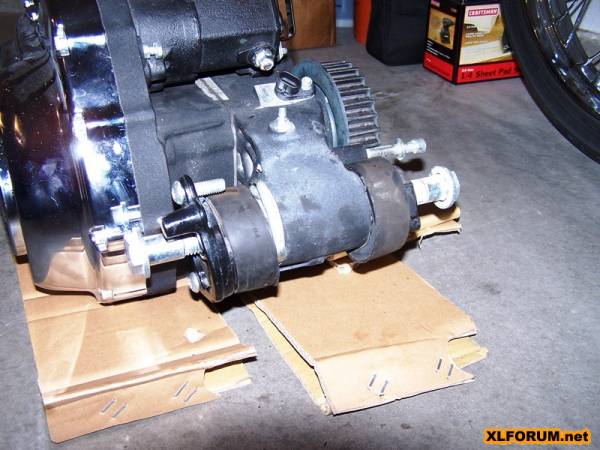
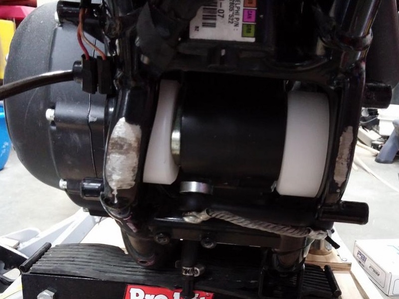
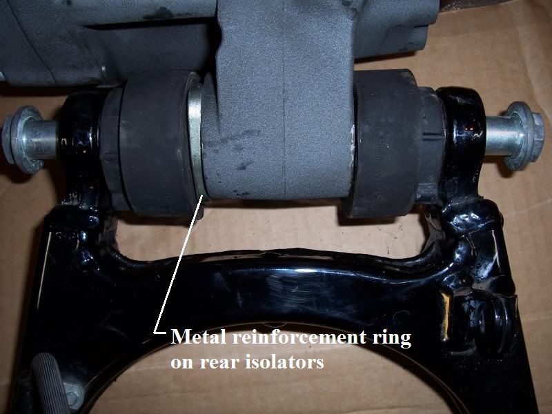
The rear mounts are a little different in design than the fronts. The rears have a metal ring built into them and the pivot shaft runs through this ring and isolator.
The rubber has bumps on them that locate them in the frame and keep them from spinning or moving.
You can see one of them below (on the swingarm side).
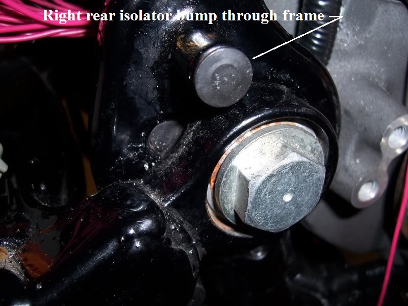
On the right side frame is the “hole” to locate the isolator.
This is the same on the front rubber and is the reason why you install / remove the motor from the clutch side.
The openings in the frame are designed to locate the bumps on the rubber mounts.
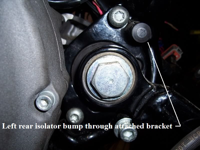
Here is a picture showing the two bumps and the rubbermount in the frame.
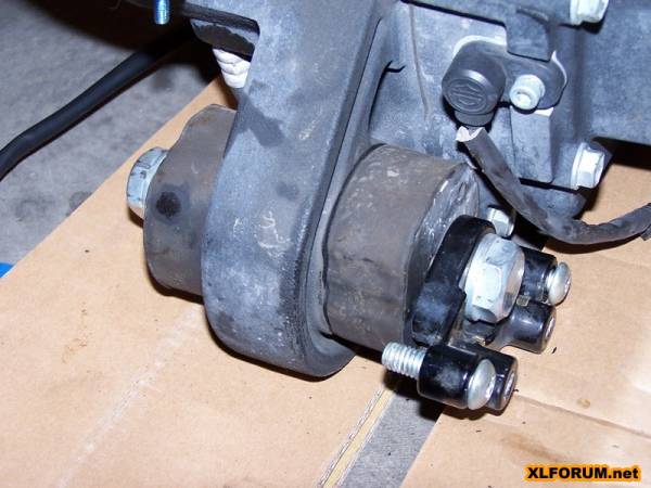
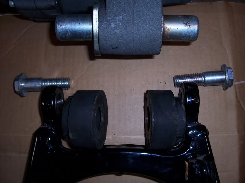
On the left side, the rear isolator is captured by a metal backing plate that pushes against the sides of the transmission rear mount lug.
This black metal retaining ring is installed after installing the motor and it compresses the rubbers together and against the side of the frame on the right.
The left passenger foot peg is bolted to it.
| Left rear isolator bump through removable bracket. 64) | Right rear isolator bump through frame. 65) | Built in anti-rotation tabs. 66) |
 |  |  |
| Rear isolator locating tabs. 67) | |
 |  |
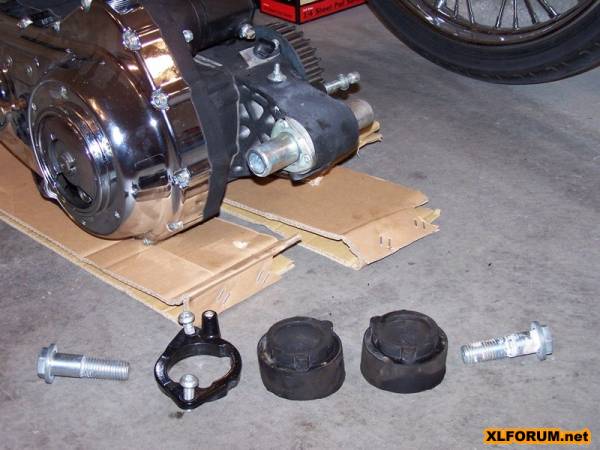
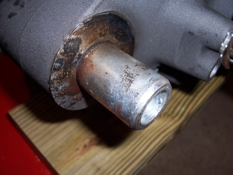
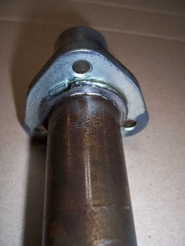
Rear Pivot Shaft
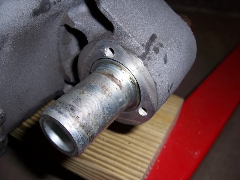
The shoulder on the shaft sits flush with the outside edge of the engine.
The pivot shaft is not a press fit into the bore but there is some tolerances involved.
One the backing plate is removed, the shaft may not easily be pulled out.
You should be able to remove it by simply hitting the opposite end with your hand or rubber mallet (after wiping any rust /debris off the shaft).
The shaft should turn freely once the retainer plate is removed but there is no “play” as the tolerance is close to an interference fit condition.
The shaft is not tapered but there is a shoulder on the shaft and there is a recessed shoulder on the engine itself.
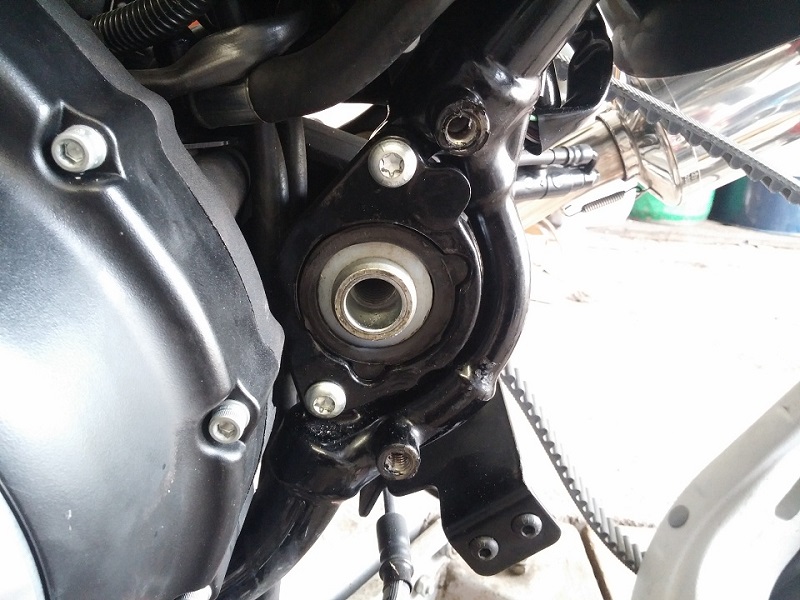
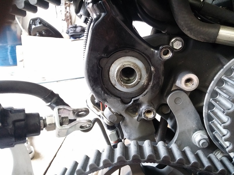
Below is a picture of the clutch side of the rear engine mount and you can see the machined shoulder on the inside.
There is no bushing in the hole, it is just machined through.
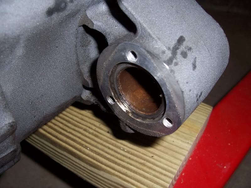
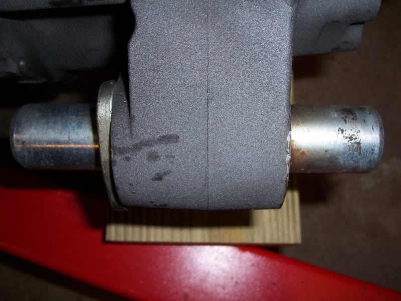
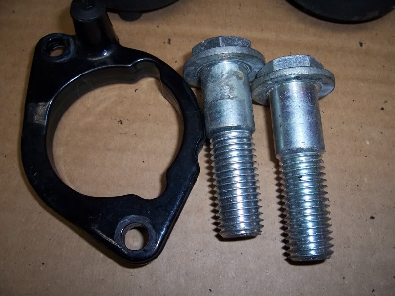
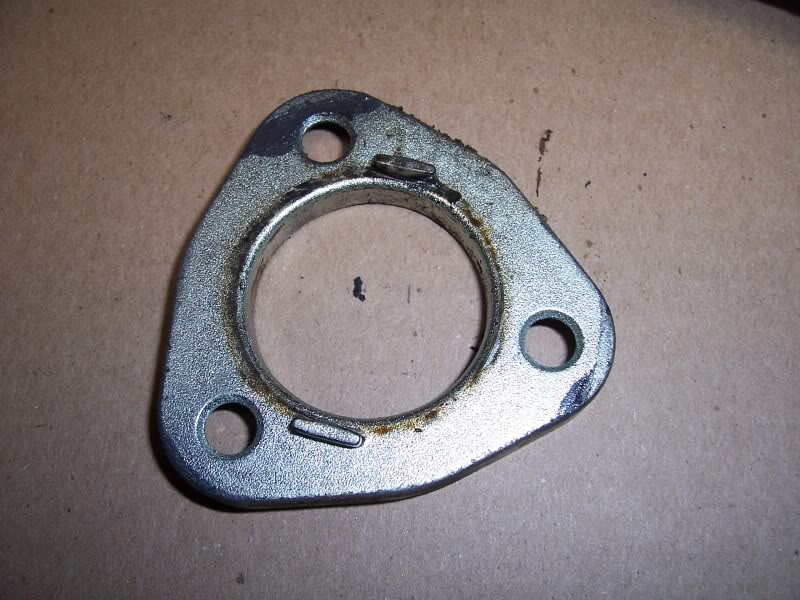
On the shoulder of the shaft there are two “flat” spots 180° from each other. The retainer plate has two small tabs that fit into the flat spots.
The shaft can still rotate a small amount until the shoulder on the shaft comes into contact with the tab.
The backing plate has two tabs that engage those flat spots on the pivot shaft and that connection locks the shaft from rotating once installed.
7)
Thanks to npaisnel of the XLForum for p/n above
45)
photos by LuxBlue of the XLFORUM