Table of Contents

EVO: Oiling & Lubrication
Engine Oil System
The Sportster Oiling Cycle is defined in the FSMs.
However, that description is vague in some of the intricate transitions of the oil path in the engine.
This page is an attempt to clarify some of the gray areas from the FSM's descriptions with further description and pictures. 1)
Links to other Oiling pages in the Sportsterpedia:
- Oil Leaks (includes oil usage)
Also a good discussion on the XLFORUM including rubbermount oil usage and crankcase pressure: 04s and up and oil use.
Oil Path Drawings: Click on a drawing below to enlarge:


Oil Feed System
Sub Documents
Role of the Oil Tank
Click Here to reference the Evo Oil Tank section in the Sportsterpedia.
Click here to reference the Oil Tank Pressure page in the Sportsterpedia.
The oil tank is both an oil reservoir and air/oil separator. Return oil comes into the tank carrying both air and oil. The oil drops to the bottom while air rises up and out the vent back to the cam chest.
Oil is gravity fed from the oil tank to the oil pump. What that means is since the oil tank is higher than the pump, gravity pushes oil down to the pump inlet but not into a running motor. It's basically a byproduct of hanging the tank above the pump. Gravity does assist pump suction however. A pressure of less than 1/4 PSI was calculated in the link below as an example on a 1998 model Sportster setup. That 1/4 PSI is just for example only as elevation and oil density will slightly change that number. The point of stating that is there is very little (but needed) gravity oil pressure on the oil at the pump inlet.
Click Here to read more on calculating Oil Tank Head Pressure at the pump in the REF section of the Sportsterpedia.
Pressure from gravity constantly pushes oil to the pump's inlet which helps the pump pick up oil through suction from there.
The higher the oil tank sits, the higher the oil level sits which increases the NPSHA which is the (Net Positive Suction Head Available) to the pump.
Click Here to read more on NPSHR vs NPSHA in the REF section of the Sportsterpedia.
The pump requires a positive push of oil to the inlet cavity to function as designed.
Pressure from gravity is also the reason oil from the tank can leak down into the motor when the motor is shut down.
Click Here to read more on Sit Sumping in the REF section.
Role of the Oil Pump
Click Here to reference the oil pump section in the Sportsterpedia.
The pressure side of the oil pump is non-regulated and delivers its entire volume of oil under pressure to the engine feed system.
Different areas of the motor have different types of pressure applied and from different sources. 7) 8)
The same applies to the oil pump.
Oil pump feed gerotor vacuum sucks oil from the attached inlet hose into the gerotor inlet cavity.
There is a vacuum created on the inlet cavity of the pump generated by the opening of the gerotors when they rotate around to the inlet side of the pump.
Vacuum is aided by the positive force of gravity from the higher hung oil tank as mentioned above. 9)
Without vacuum, the pump would not be able to function properly and would starve the pump especially at higher RPM.
As the volume between the feed gerotor gears increase (with engine RPM), the suction on the feed line also increases. 10)
Likewise with lower RPM, the suction decreases.
Too low suction and the gerotor cavities will not completely fill with oil especially on higher RPM and system oil volume will suffer.
Too much vacuum and oil vapor may be pulled out of the oil stream and cavitate / damage the oil pump.
Thankfully, the MoCo has designed the OEM oiling system in the Sportster to keep this from happening.
The oil pump pressurizes the oil delivered to the outlet cavity in the pump.
One teeth cavity of oil at a time is rotated from the inlet side to the outlet side in the pump. The closing of the gerotor teeth afterward combined with the next teeth full of oil continues squeezing (pressurizing) the outlet cavity. The faster the rotation, the higher the pressure that is created in the outlet of the pump.
The engine is force-fed oil by system pressure to the oil filter pad where a check valve (1986-1990) or check ball (1991-up) is opened at 4-6 PSI. The discharge side of the pump forces oil to the engine to lubricate Lifters, Rocker arm bushings Valve stems, Valve springs, Pushrods and Lower connecting rod bearings.
Engine Oil Pressure and Testing
Click Here for the “Sportster Oil Pressure (1957-Present)” page in the REF section of the Sportsterpedia“.
That page consists of where to test, expected oil pressure for the respective year models and a link to the page for installing a pressure gauge.
The FSMs say the oil pump is non-regulatory and delivers its entire volume of oil under pressure to the motor. But that is not the entire story.
Cold oil flows slower and at higher pressure than hot oil. During start-up of a cold (ambient temp) engine, oil is thicker, oil pressure will be higher than normal and oil circulation will be somewhat restricted to flow within the oiling path. Oil pressure should be checked when hot (operating temp) to meet the specs in the manuals. As the oil heats up it gets thinner, flows faster and pressure is lowered.
The oil path, as designed, creates variable system pressures. The restrictions in the oil feed path (hose size, routing paths, orifice sizes, etc) manipulate oil flow and oil pressure. Each restriction in the feed path, whether chamber size, bends or orifice size, lowers the flow volume and pressure downstream of the restriction. I.E., A restrictor in the end of the pinion shaft will lower the amount of oil that gets passed it to the crankpin/lower end bearings but the smaller amount of oil that does flow past the restrictor flows at a faster rate. And lowering the amount of oil to the pinion shaft also sends more oil up to the rocker boxes. There will be lower pressure at the crankpin / lower end bearings than at the oil pump. There will also be lower pressure at the rocker arms then there will be at the oil pump. The OEM specs were meant to show the amount of pressure that should be present at the pump without further modifications to the feed system. Altering the OEM feed path will change the pressure at the pump to the extent of the modification.
Restrictions in the oil path harness and manipulate the pressure created at the pump. Pressure is always greatest at the oil pump outlet. As the oil passes each restriction (bends, smaller passages, orifices as well as elevation), pressure will be lower from thereon depending on how much of a restriction is created and for how long.
Oil volume to the motor is dependent on pump capabilities and RPM. When an engine is operated at higher speeds; the volume of oil circulated through the oiling system increases, resulting in higher oil pressure throughout the feed path. As engine speed is reduced, the volume of oil pumped is also reduced, resulting in lower oil pressure throughout the feed path.
Oil Pressure Light
If the oil pressure light stays on at speeds above idling, always check the oil supply first.
Then if the oil supply is normal, look inside the oil tank to determine if oil is returning to the tank from the return hose with the engine running.
If oil is returning to the tank, there is some circulation and the engine may be run a short distance if necessary.
If no oil is returning, shut the engine off until the trouble is located and fixed.
Conditions causing the oil light to stay on;
Low or diluted oil supply,
Or a plugged lifter screen (86-91) under the plug between the tappets,
A grounded oil signal switch wire,
Faulty oil switch,
Faulty or weak oil pump,
Clogged feed hose (in freezing weather from ice and sludge preventing the circulation of oil).
Year Model Specifics
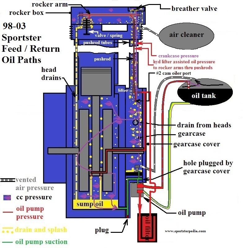
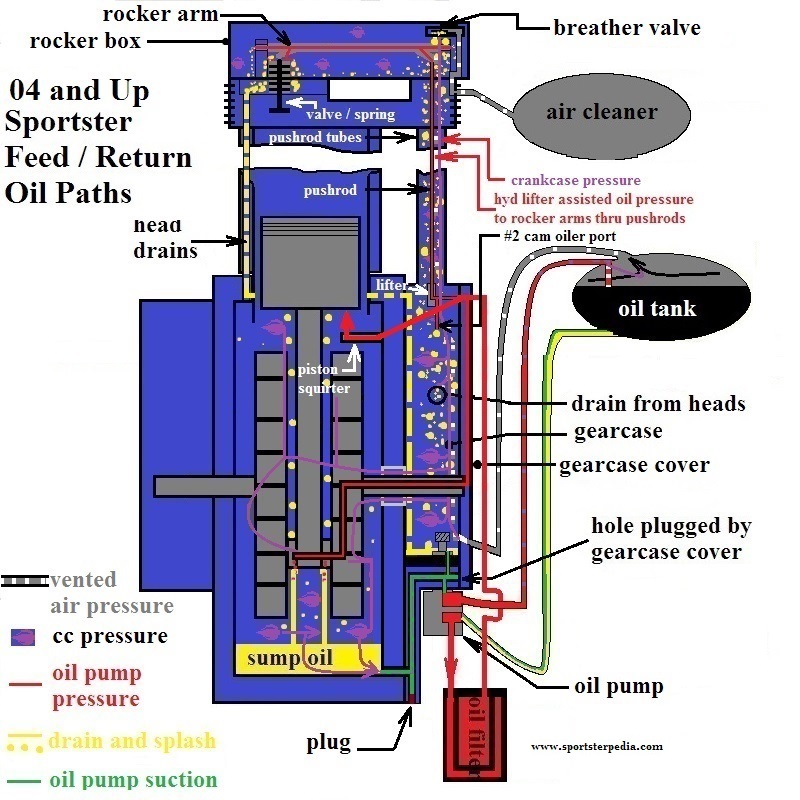
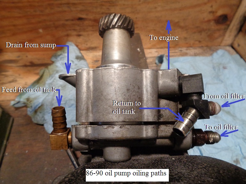
Refer to the drawings at the top of this page from the text below.
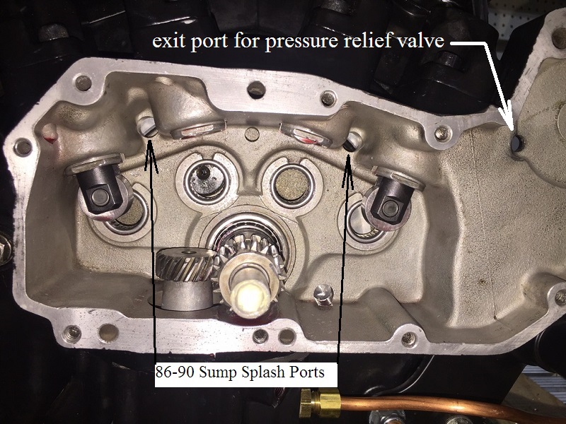
1986-1990 engines
Oil pump feed gerotors send pressurized oil up through a cavity in the oil filter housing via an external hose from the pump to the filter housing (pad). The oil leaves the filter via an external hose and returns back to the oil pump from a second external hose. The first hose from the pump to the filter pad has smaller orifice fittings than the hose back to the pump from the filter pad.
There is a high pressure oil bypass system built into the filter pad behind the oil filter that dumps excess oil pressure (above 30-35 PSI, when and if present) onto the cam floor for scavenging back to the tank. Oil from the filter is routed into the pump and through a check valve or check ball mounted in the oil pump. Oil leaves the check and enters a hidden passage in the cam chest floor up through the cam cover internal passages to the pinion bushing / shaft. Oil is sent thru the pinion shaft to internal holes in the right flywheel to the crankpin and out to the lower end rod bearings. This is the lower end of oil feed pressure. Oil is also sent up past the pinion bushing thru an internal passage in the cam cover to the upper feed galley. There is a hole in the upper cover that opens to a hole in the upper right case. Oil leaves the cam cover into the upper case galley into each intake lifter bore. There are cross drilled holes from each intake lifter bore to it's corresponding exhaust lifter bore. So the intake lifters get oiled first, then the exhaust lifters get oiled. Restrictions in the lifter assemblies lower the amount of oil up the pushrods to the rocker arms. Oil flows up inside the pushrods into the rocker arms where rocker arm bushings and valves are lubed. This is the end of oil pump pressure in the top end.
1991 engines
Oil pump feed gerotors send pressurized oil up through a cavity in the filter housing via one external hose to the oil filter pad. The oil leaves the filter and is routed past a check ball (opening at 4-6 PSI) in the filter adapter and through a passage in the upper case's oil feed galley. There is a high pressure oil bypass system built into the case behind the oil filter that dumps excess oil pressure (above 30-35 PSI, when and if present) onto the cam floor for scavenging back to the tank. From the feed galley, oil is sent to each lifter by individual cross drilled holes so each lifter has it's own oil flow. Restrictions in the lifter assemblies lower the amount of oil up the pushrods to the rocker arms. Oil flows up the pushrods into the rocker arms where rocker arm bushings and valves are lubed. This is the end of oil pump pressure in the top end. Oil is also sent from the upper feed galley down to the pinion bushing / shaft to a hole in the right flywheel then crankpin / lower rod bearings. This is the lower end of oil feed pressure.
1992-2003 engines
Oil pump feed gerotors send pressurized oil up through a cavity in the filter housing via one external hose to the oil filter pad.
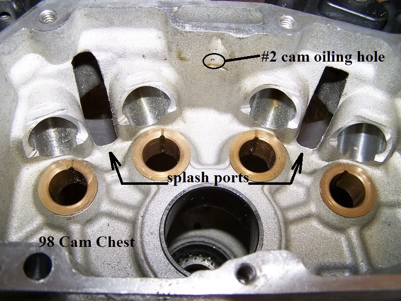
The oil leaves the filter and is routed past a check ball (opening at 4-6 PSI) in the filter adapter and through a passage in the upper case's oil feed galley. 1992-up engines do not use an oil pressure bypass system. The high pressure oil bypass was deleted with the addition of a cam squirter hole drilled from the upper cam case through to the upper feed galley. A (.060”) hole from the upper feed galley sprays oil onto #2 cam gear teeth. Oil is transferred to all cam gear teeth by way of the gear meshing action. From the feed galley, oil is sent to each lifter by individual cross drilled holes so each lifter has it's own oil flow. Restrictions in the lifter assemblies lower the amount of oil up the pushrods to the rocker arms. Oil flows up the pushrods into the rocker arms where rocker arm bushings and valves are lubed. This is the end of oil pump pressure in the top end. Oil is also sent from the upper feed galley down to the pinion bushing / shaft to a hole in the right flywheel then crankpin / lower rod bearings. This is the lower end of oil feed pressure.
2004-Up engines
Oil pump feed gerotors send pressurized oil up through a cavity in the filter housing via one external hose to the oil filter pad.
The oil leaves the filter and is routed past a check ball (opening at 4-6 PSI) in the filter adapter and through a passage in the upper case's oil feed galley. 1992-up engines do not use a oil pressure bypass system. The high pressure oil bypass was deleted with the addition of a cam squirter hole drilled from the upper cam case through to the upper feed galley. A (.060“) hole from the upper feed galley sprays oil onto #2 cam gear teeth. Oil is transferred to all cam gear teeth by way of the gear meshing action. From the feed galley, oil is sent to each lifter by individual cross drilled holes so each lifter has it's own oil flow. Restrictions in the lifter assemblies lower the amount of oil up the pushrods to the rocker arms. Oil flows up the pushrods into the rocker arms where rocker arm bushings and valves are lubed. There are two additional holes through the feed galley to the piston squirter units attached behind the cam wall in the crankcase. This is the end of oil pump pressure in the top end. Oil is also sent from the upper feed galley down to the pinion bushing / shaft to a hole in the right flywheel then crankpin / lower rod bearings. This is the lower end of oil feed pressure.
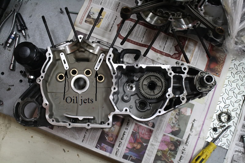
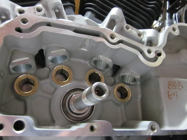
2004-Up Piston Squirters
The rubbermounts received an addition of piston oiler jets in the previous year splash port locations. The holes in the cam chest wall are no longer open thru holes to the crankcase. Instead, holes are drilled to the crankcase thru the upper feed galley beside lifter oil passages. Oil jets were installed on the crankcase side of the wall, blocking off the holes in the wall to the crankcase. Oil flows down to separate units with jets facing up. The jets create a dual oil spray in a controlled direction upward to the pistons. Pressurized air / oil mist leaves the crankcase through the bearing on the pinion shaft into the cam chest and thru oil pump scavenge to the tank. There is no seal on the pinion bearing and air pulses into the cam chest to be pulled up into vertical passages between the cam slots.

Oil Drainage
Sub Documents
Drain oil is not a part of the feed pressure system. Drain oil is non-pressurized oil that exits the last orifice in the respective pressure path and eventually finds it way to the crankcase or cam chest floor awaiting to be scavenged by the oil pump. Once pressurized oil exits it's last orifice, pressure dissipates and is generally (at atmosphere) from there on. However it is subject to the variable changing crankcase air pressure. Drain oil aides in splash lube since some of that is picked up into air/oil mist and slung onto the moving parts by crankcase pressure pulses and the moving parts themselves.
There will always be an amount of oil left in the cases after shutdown. A large portion of drain oil hits the bottom of the crankcase or cam chest and exits the motor by way of the oil pump and sent back to the oil tank during operation. During shutdown, there will be oil in the feed passages, up top in the boxes, on the flywheels and cams etc. that will fall back down to the cam chest and crank case floors and will not be scavenged since the motor is not running.
There may also be a certain amount of oil that drains into the motor from the oil tank after shutdown. This has been affectionately hailed as Sit Sumping on the XLForum. Click Here to read more on sit sumping in the Sportsterpedia. There are generally 2 areas of suspect where oil can drain into a non running motor; oil filter pad or oil pump. (1) The oil check ball in the oil filter adapter can allow oil to seep through the filter. (2) Too wide of clearances or worn parts in the oil pump can allow oil to seep into the cam chest. Keep in mind that oil expands when hot. So checking the oil level as soon as you shut off the motor then checking it an hour later may only show the oil shrinking when cold and may not mean the loss on the dipstick went into the motor. Checking when the oil cools down then checking hours/days/weeks later may give better results.
Oil Return System (scavenge)
Role of Crankcase Pressure
See also in the Sportsterpedia:
Positive crankcase pressure (piston downstroke) aides the scavenging ability of the pump 13). Just like the feed side has a positive push from the higher strung oil tank, the return side gets it's positive push from piston downstroke which increases the NPSHA (Net Positive Suction Head Available) to the pump through the passage from the sump.
Click Here to read more on NPSHR vs NPSHA in the REF section of the Sportsterpedia. The pump requires a positive push of oil to the inlet cavity to function as designed and the positive push from downstroke functions to usher oil to the exit port in the sump.
Negative pressure (piston upstroke) makes the pump's job harder since the pump is fighting the crankcase vacuum. 14). And crankcase vacuum decreases NPSHA to the pump. The pump sucks crankcase oil only when oil is present at the exit port in the rear of the sump. And the return gerotors are larger than the feed gerotors which means the pump will try to remove more oil than it can feed to the motor. Once the oil is scooped up in the crankcase, air is the only thing left to scavenge. This is why you'll see a gulp, then another gulp of oil coming back into the tank. In-between the gulps of oil are gulps of air that separate from the oil and rise once exiting the return hose into the tank. The more vacuum (negative pressure) in the crankcase, the less oil the pump can pick up on average.
Role of the Oil Pump
Click Here to reference the Evo oil pump section in the Sportsterpedia.
Oil pump pressure and crankcase pressure work together to remove oil out of the motor.
The return side of the oil pump is non-regulated and delivers its entire volume of oil under pressure to the return system. However, return (drain) oil is not as available as is feed oil and availability determines (entire) volume of oil.
Crankcase Inlet:
Oil pump return gerotor vacuum sucks oil uphill from the crankcase sump port through a drilled passage between there and the rear scavenge inlet cavity (duck bill) of the oil pump. The crankcase sump outlet is below the scavenge pump inlet. So the oil has to be sucked uphill to get to the pump and then back to the tank. Just as in the feed side, a vacuum is created on the inlet cavity of the return side generated by the opening of the gerotors as they rotate around to the inlet side of the pump. Pump vacuum is aided by the positive force of piston downstroke. As the volume between the return gerotor gears increase, the suction on the return path also increases (as long as there is oil at the sump port to pick up). Likewise with lower RPM, the suction decreases. Too low of suction and the oil path from the crankcase loses prime and the gerotor cavities will not completely fill with oil especially on higher RPM and return oil volume will suffer. This will lead to a condition called wet sumping.
Click Here to read more on Wet Sumping in the REF section.
The oil pump pressurizes the oil delivered to the return outlet cavity in the pump.
One teeth cavity of oil at a time is rotated from the inlet side to the outlet side in the pump. The closing of the gerotor teeth afterward combined with the next teeth full of oil continues pressurizing the outlet cavity. The faster the rotation (RPM), the higher the pressure that is created in the outlet of the pump. The slower the RPM, the lower the pressure will be on the outlet. With the return hose being the only path from there to the oil tank, the return pressure to the tank is only restricted by the hose ID, gravity and the air pressure in the tank (which is vented back to the cam chest). Since the return gerotors are bigger than the feed gerotors, some of what the pump returns to the tank is air (which is compressible). The presence of air in the pressure side of the return lowers the pressure delivered to the tank. Lesser restrictions build less pressure in the return path as well. So even though the return side is bigger than the feed side, return pressure to the tank could (actually should) be lower than the feed since there are less restrictions and some of that pressured volume is relieved by the presence of air.
Cam Chest Inlet (1998-Up):
Starting in 1998, an additional inlet was added to the oil pump to scavenge the cam chest as well as the crankcase. 1997 and prior oil pumps do not have the additional cam chest inlet.
1986-up oil pumps:


Splash Lubrication
See also in the Sportsterpedia:
Splash lubrication is generated by crankcase air pulses and the spinning parts in the engine.
- Crankcase air pressure is generated by the up and down movement of the pistons. The oil level in the sump of the crankcase should never touch the bottom of the flywheels nor should the oil level get to the bottom of the cams in the cam chest.
- There is no oil pump pressure in the crankcase or the cam chest. Static oil pump pressure has already been dissipated by the time it reaches the crankcase and the oil past the end pressure points is either considered splash or drain oil until it gets back in the tank.
- The downstroke of the pistons causes the volume underneath the pistons to decrease which puts air pressure above the oil (and pushes oil to the scavenge passage in the sump). 18) This pressure is multi use;
- It helps to push sump oil to the oil pump scavenge port in the sump, (the scavenge side of the pump pulls a vacuum on the sealed passage from the sump outlet to the pump) 19)
- It also initiates the splash and mist process as the compressed air above the oil is ready to spring up when the piston rises.
- Then the upstroke of the pistons create an upward vacuum bringing some of the oil from the sump with it. With little to no (piston ring) blow-by and a check valve on the breather system; crankcase pressure is essentially cycling between atmospheric and negative (pressures) as the pistons go down and back up (remember, due to the common crankpin 45 degree design, a Harley motor is a variable volume crankcase, unlike most motors) 20)
- This pulsating crankcase air (with varying changes in velocity) creates splash oil which is bounced about in the crankcase by the next downstroke. This also creates an air / oil mix when tiny particles intertwine with the oil in suspension. The two don't actually mix as does sugar and water. So separating them back apart is fairly easy if you add an obstacle for that 'mix' to collide into. Anything that air/oil mist hits along the way to the breather valve(s) will separate some of the oil from the air. The last obstacle is widely known as the breather or umbrella valve(s).
- The movement of the pistons and flywheels splash oil around in the engine.
- Gravity oil (from the drain ports in the heads) returns to the crankcase or gearcase (respective to year model);
- On 1986-2003 engines, gravity oil falls into the crankcase sump area.
- On 04 and up engines, gravity oil falls into the gearcase.
Some CC Pressure is needed: Some of the oil is picked up by the piston upstroke and mixed with the air pressure in the form of mist. The mist and splash oil lubricates crankcase components.
And they are also carried into the gearcase compartment to help lubricate the cams and pinion / oil pump gears. Splash and gravity oil from the connecting rods, crankshaft, rocker boxes and head/cylinder drainage holes serve to lubricate;
- Cylinder walls
- Pistons, piston pins
- Cam gears and bushings
- Main bearings
Excess CC Pressure is vented out of the engine: See Crankcase Ventilation in the link above. Excess unvented crankcase pressure will simply build up inside the engine and eventually blow out gaskets / seals in the engine. The pressure (even though needed) would build high enough to be detrimental to the engine. So unusable high pressure is vented out of the engine to keep in (regulate) a certain amount of usable internal pressure.
- Splash oil
(from the up and down movement of the connecting rods, crankshaft and pressure generated under the pistons on downstroke) - Crankcase pressure mixed with oil in the sump area serves to splash (and lubricate) the moving parts such as;
- Cylinder walls
- Pistons, piston pins
- Cam gears and bushings
- Main bearings
- Crankcase pressure also serves to help 'push' oil from the sump into the scavenger port of the oil pump.
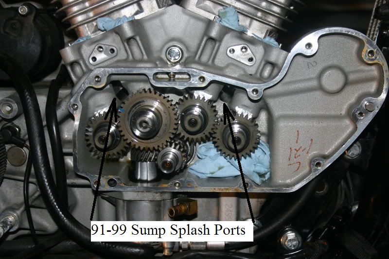
1991-1999
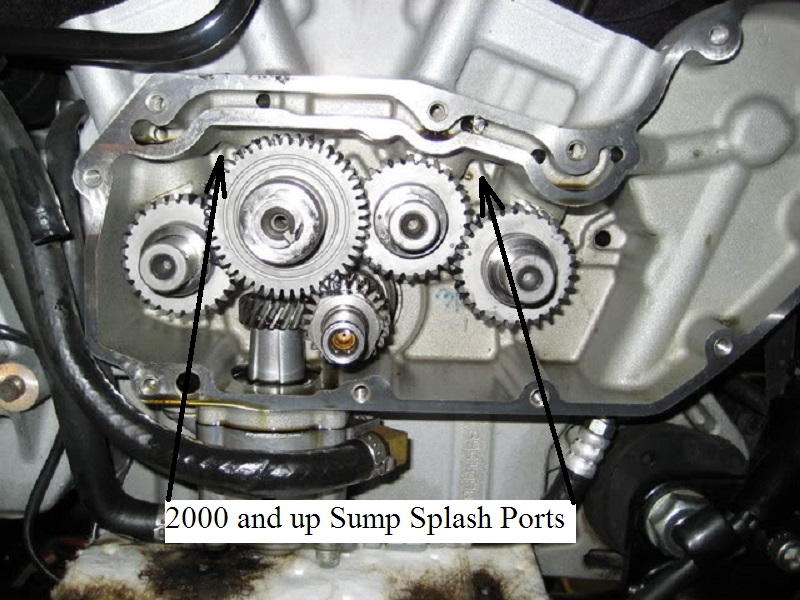
2000-2003
Oil Filter - Function & Control
Also see the REF section on Understanding Oil Filters
The oil pump sends pressurized oil to the oil filter. There are two cavities inside the oil filter.
Unfiltered oil enters the outside cavity, passes thru the filter media and filtered oil exits thru the filter adapter in the center.
General Overview

 A) … Incoming 'Dirty' Oil on Outside of Filter Material (RED color for dirty oil)
B) … Filter Material inside the Oil Filter
C) … Bypass Valve - Passes dirty oil when necessary to prevent oil starvation
D) … Output of Oil from the Filter - (GREEN color for filtered oil - RED for UNfiltered)
E) … Check Valve keeps oil from draining into engine when not running
F) … Oil Supplied to Engine - Could be Clean or Dirty depending on Bypass Valve operation
Sometimes, these exist
G) … Anti-Drain Back Valve in the Oil Filter to prevent the filter being empty
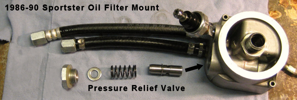
H) … Pressure Relief Valve on 1986-1991 models (in the oil filter mount)
(This overview is not intended to present or explore every detail of any of these parts. See the REF section on Understanding Oil Filters)
The oil pump is hydraulic and moves oil efficiently. It is very strong due to being directly driven and having minimal gear lash in the pump. It will pump forcibly IF NECESSARY. The flow rate capability (GPM) will vary somewhat based on resistance and the efficency of the pump and the level of wear within the gerotor gears.
The pump is capable of 100's of PSI. The amount of oil passed per revolution is nearly constant, thus the GPMs will increase as the RPMs increase.
It is the resistance to flow that will determine the actual pressure (PSI). If there is little resistance, then the PSI pressure will be low. If there is much resistance, the constant force of the pump will create high (or very high) PSI pressure.
The physical hoses & routing (bends/kinks/etc.) will create some resistance (getting to (A)), the filter material (B) will create some resistance, the check valve (E) will create some resistance and the engine oiling system will create some resistance… Of course, the oil temperature affects the viscosity of the oil. Colder Oil = Thicker Oil, which increases the resistance to flow. Combined at any one specific time, these factors create the PSI necessary to push the GPM load that the pump is supplying.
The density of the filter material (B) (microns) & the level of contaminant saturation in the material will affect the resistance. Of course, the level of contaminant saturation varies with usage.
The bypass valve (C) is intended to prevent oil starvation in the engine when the filter passes oil poorly - but to do so, it must pass UNfiltered oil around the filter material. It does this only when the Bypass Valve PSI rating is exceeded. This only occurs when the filter material cannot pass enough oil THRU it, thereby creating a higher oil pressure on the input side (due to filter resistenace to flow). This is sensed by the bypass valve (C), which then opens to continue supplying some oil around (rather than thru) the filter material to keep the engine oiled. Physically, the implemented bypass may be at the top or bottom of the filter, but the function is the same.
The Anti-Drain-Back Valve (G) prevents the oil inside the filter from escaping back out the input side of the filter (A). This maintains an oil reservoir (inside the filter) that is ready to supply the engine immediately on start-up, rather than waiting for new oil to fill the filter cavity once the newly started engine begins to pump oil to the filter.
In a similar way, the Check Valve (E) helps to prevent oil draining out of the filter (or being gravity drained from the oil tank, thru the pump & filter) into the engine oiling system when the active flow stops (engine is not running). It has a very low PSI setting so that even a very low movement of oil will pass thru to begin oiling the engine.
The Pressure Relief Valve (H), which is only on the 1986-91 XL models, is set for about 30psi. This guarantees that the pressure to the oil filter is below that level. But that level of pressure is only present when the oil is cold. Once warm, the normal pressure is below 30psi all the time, even at high RPMS 25)
While both are differential valves, the Filter Bypass Valve (C) functions on a difference in pressure from one side of the filter material to the other side, while the Pressure Relief Valve (H) functions on absolute input pressure because there is no pressure on the other side of it (in the gearcase or crankcase).
The Bypass Valve (C) functions differentially because there is supplied oil (under pressure) at both sides of the valve - One side is supplied from the outside of the filter material and the other side is supplied pressure from the oil that has passed thru the filter material (being at the outlet of the filter). This means IF the filter material flows well (being new and/or clean with warmed up oil viscosity) then both sides of the material will be close to the same pressure level, with the material presenting little resistance. BUT, if the filter is very restrictive (clogged or oil is cold & thick) the flow from passing THRU the filter will be present a significantly less pressure on the Bypass Valve output side, thereby calling for the Bypass Valve (C) to open.
To be clear, the Bypass Valve (C) doesn't care if there is 5psi on each side or 20psi on each side, it will not open until there is a difference between the incoming side of the filter & the outgoing side of the filter. If rated at 12psi, the difference must be 12psi before it opens (17psi in vs 5psi out -or- 32psi in vs 20psi out). If so rated, the difference must be 12psi. This can/will occur when the oil is cold & thick or when the filter is sufficiently clogged to minimize oil flow thru it.
In contrast, there is no pressure on the output side of the Relief Valve (H). It only has pressure on the input side, which, when it reaches 30psi, will open to allow some volume to bleed off, thereby reducing the pressure in the line. Since there is no pressure on the output side of the Relief Valve (H), dumping into the gearcase or crankcase, the differential pressure is always perceived as XX (inside) psi to 0 (cam/crank) psi.
It should also be noted that in normal operation, the bypassing of the oil filter for brief periods (like thick viscosity) will have little affect on the longevity of the engine. However, a clogged oil filter that is continuously bypassing oil around the filter material, will eventually sufficiently contaminate the engine oiling system to cause damage. Oil filter replacement on the recommended schedule (or sooner) is a precautionary chore to keep the engine supplied with clean oil.
These two references are a good read:
http://www.mgnoc.com/article_oil_filters_revisited.html
https://www.xlforum.net/forum/sportster-motorcycle-forum/sportster-motorcycle-motor-engine/sportster-motorcycle-bottom-end/195572-oil-filter-functioning?t=2071942
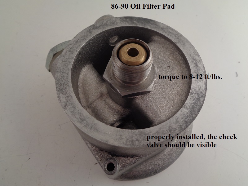
Oil Filter Mount
Sub Documents
See also Oil Filter Fitment in the REF section of the Sportsterpedia.
AKA Oil Filter Pad
—– 1986-1990 Models —–
The 1986-1990 oil filter pad is an upgrade to the L-1984-1985 version.
The 1986-1990 version still has 2 hoses to and from the filter pad but the fitting size changed on one of the hoses.
A high pressure relief valve was also added to the incoming (non-filtered) cavity. Oil filter mounting threads for all models (L1984-up) are 3/4”-16.
—– 1991-later Models —–
In 1991, the oil filter mounting pad was cast into the front section of the right case so no longer is there a separate bolt-on part for the oil filter.
The high pressure relief valve is also incorporated into the new filter pad mount and operates the same as in 1986-1990 models.
You can see it by removing the cam cover and looking up in the area (behind the oil filter.
1992-up Sportsters do not have the oil pressure relief valve.
A small hole was drilled between the upper feed galley and the cam chest to keep pressure from getting too high. This hole doubles to splash oil on #2 cam gear.
The oil filter adapter is the threaded part that the filter screws onto.
 26)
26)  27)
27)
Oil System Controls
Oil Pressure Regulator - 1986-1991 Models ONLY
Sub Documents
Also see 1986-1990 Oil Filter Mount Mods for modifications to the pressure regulator system.
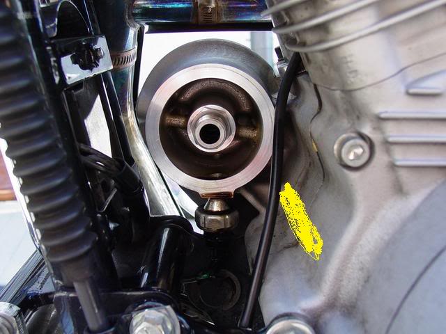
—– 1986-1990 Models —–
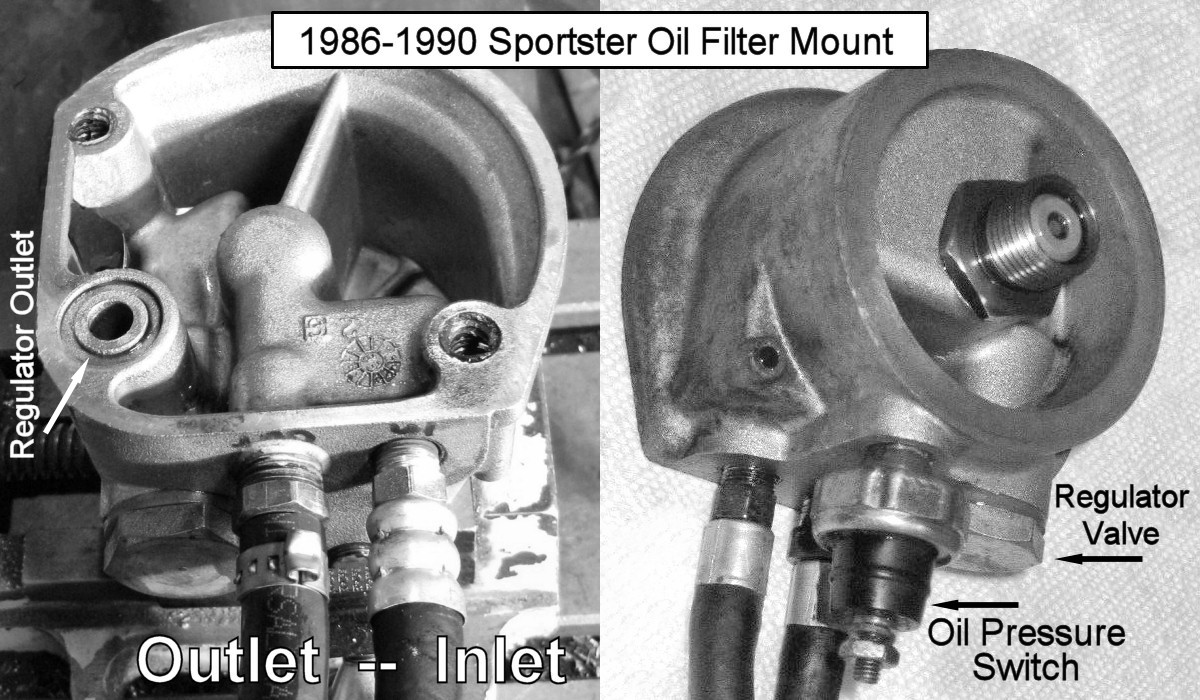 |
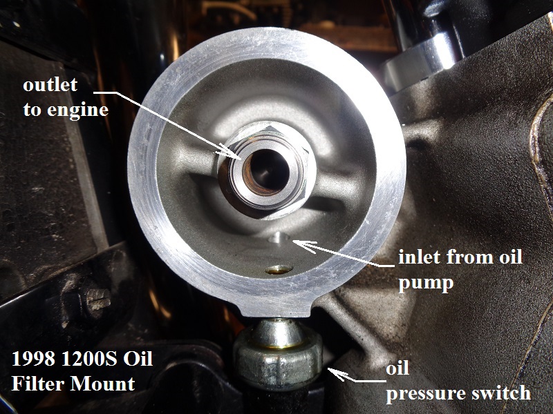
| 1986-90 Oil Filter Mount 28) | Pressurized oil comes into the gearcase from the hole at the arrow on the right. 29) |
 |  |
With the new Evolution engine in 1986, an oil pressure regulator (relief valve) was implemented to bleed off some of the oil when the pressure thru the filter became to high.
The spring loaded pressure valve was built into the oil filter mounting pad.
There is a passage from the filter pad relief valve into the cam gearcase.
The discharge from the relief valve drains down into the gearcase.
Then that 'extra' oil and is routed to the crankcase sump through a hole in the case wall and gets pumped back to the tank.
The spring-loaded pressure regulator opens at about 30 psi.
However, it is usually only regulating when the engine oil is cold.
When the engine is warm, the valve is typically shut, since pressure is usually below 30 psi even at high rpms. 30)
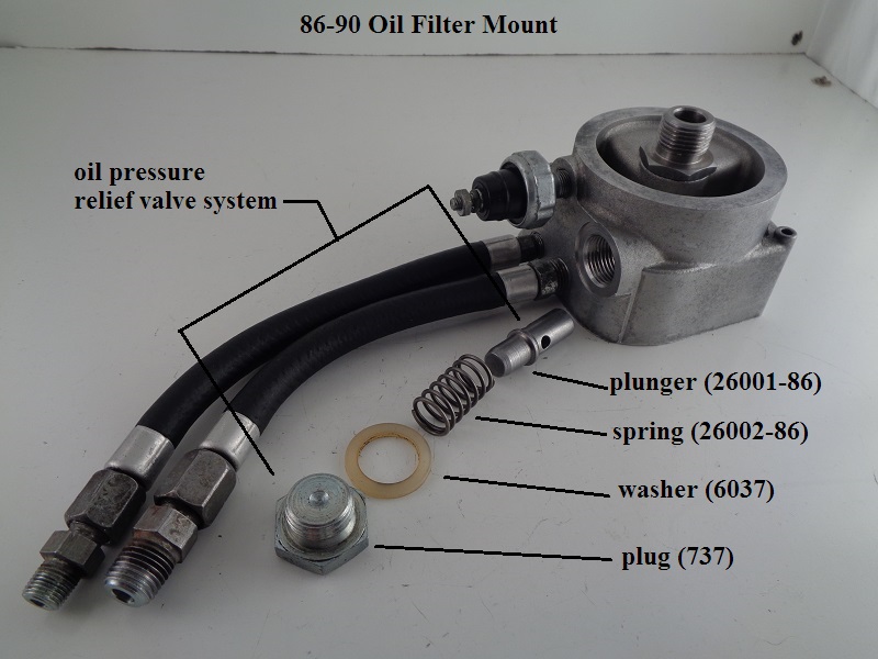
The pressure relief parts for 1986-1990 are:
| HD Part# | Description |
| 737 | PLUG |
| 6037 | WASHER |
| 26001-86 | PLUNGER |
| 26002-86 | SPRING |
The plug installation torque is 15-20 ft-lbs.
—– 1991 Model —–
In 1991, the entire oil filter mount was incorporated into the right crankcase half. It still used a supply & return hose to flow oil thru the filter.
The implementation of the pressure regulator in this version used the same spring & plunger as before. It was mounted into a hole from the gearcase side of the mount. Then, a new plug, with a hole drilled in the center of the hex head, held the spring & plunger in place. This allowed oil to escape from the incoming side of the filter, thru the plug hole and into the gearcase, where it eventually made it to the crankcase sump & was returned to the oil tank.
As in the previous implementation, this allowed the relief valve to bypass oil thru the plunger when activated instead of pumping it thru the filter. The relief pressure was the same, being about 30psi.
Since the new plug is already in the gearcase, the washer (6037) was eliminated.


The pressure relief parts for 1991 are:
| HD Part# | Description |
| 742 | PLUG |
| 26001-86 | PLUNGER |
| 26002-86 | SPRING |
(It should be noted that the 1991 & 1992 parts catalogs list these pressure relief parts for all models, although they are not illustrated for either year. However, I have only been able to visually verify the existence of these parts on the 1991 model engine. Harley Tech Tips #26 & #27 seem to support this, but there might have been some early 1992 models with the 1991 implementation. Research continuing.)32)
XLFORUM Discussion Threads on the Pressure Regulator
Oil Pressure Regulator - 92 and Up Models
The oil pressure regulating unit was discontinued for 1992 and up engines (and 1991 replacement cases).
On 1992-Up engines, excess oil pressure is constantly shared between the pinion shaft and a passage drilled in the upper feed galley of the right case.
It is a double duty (hole) drilled from the center open feed galley down toward #2 cam gear teeth.
This passage is on the oil filter output side of the lifters and crankpin and thus lowers system pressure to both as an additional outlet.
It sprays oil onto #2 cam gear teeth which in turn splashes oil to all cam gears by way of the gears meshing.
The hole is app .060“ ID which is the same size as the pinion shaft restricted orifice.
| 1998 cam chest. 33) |
 |
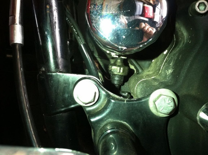
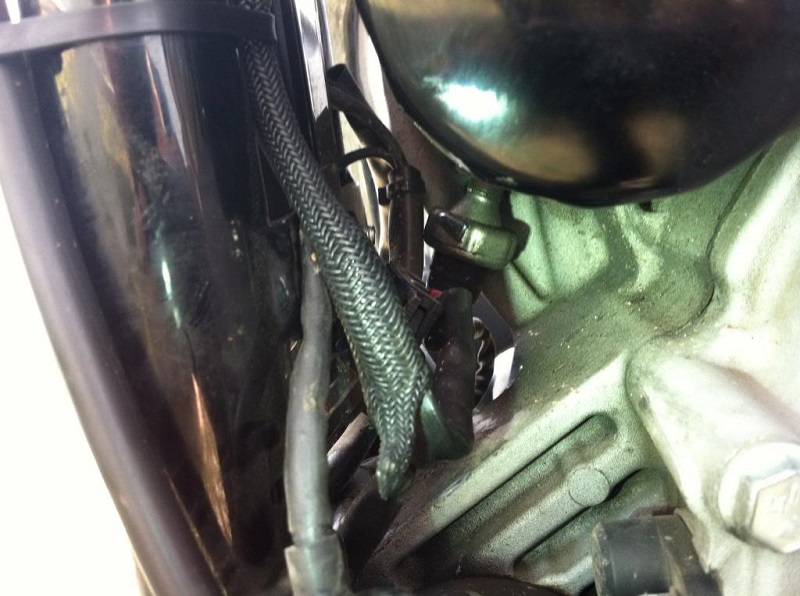
Oil Pressure Switch
Sub Documents
See also in the REF section of the Sportsterpedia:
* Homemade Oil Pressure Light in case you don't have one.
* Testing the Oil Pressure Switch
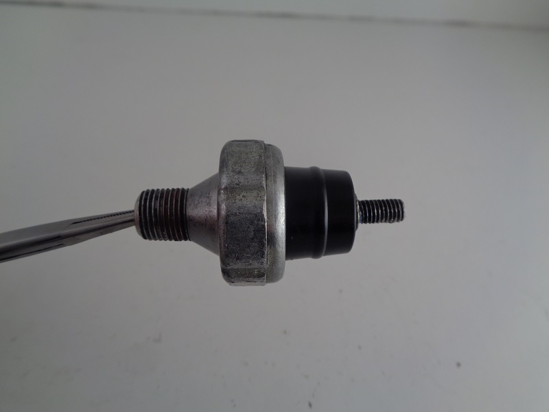
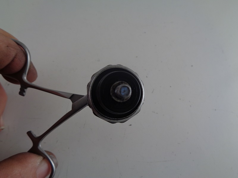
The oil pressure switch (for the oil light) is a pressure actuated diaphragm type on / off switch basically.
The diaphragm is spring loaded and held against its contact point when the engine is not running or the when the oil pressure is too low while running.
With the switch contacts touching, this closes the circuit to the oil pressure light and causes it to light up (with the key on, of course).
When the engine is fired up, oil pressure builds in the filter pad, activates the oil light switch and opens the oil pump check valve (or check ball respectively) allowing oil to enter the engine.
Oil pressure is sensed by the oil pressure switch.
By the time the engine reaches over 1000 to 1200 rpms, the oil pressure is sufficient to move the oil pressure switch diaphragm completely off it's seat.
This opens its contact point, breaking the circuit to the oil pressure light and it goes off.
Cold cranking oil pressure can reach between 30 PSI and upwards of 60-100+ PSI.
Oil pressure will vary under normal riding conditions. See above for expected oil pressures.
However, idle (hot) oil pressure will vary from 7-17 PSI on most models.
So, at idle, the oil check valve (or ball) may only be opened just past it's cracking pressure (not to it's end of travel).
In the Case of a Defective Oil Pressure Switch:
This switch opens and closes the contacts to the oil pressure light.
The oil light is important to have since if it is not working, it can be assumed that you have little to none oil flow to the engine.
If the pressure switch doesn't operate the light it should be checked for proper operation or replaced.
For the $30 or whatever you save by not buying the switch, it's just not worth it to not have the low engine pressure idiot light working. 34)
If your motor is ready to run and you need to test it then you can connect a piece of clear hose so you can see oil in it.
Don't plug the end till you've primed the pump (if applicable).
Replace a defective switch as soon as possible.
Part # (26554-77)
Torque:
Pressure switch: 5-7 ft/lbs.
Wire nut: 4-10 in/lbs.
| Oil pressure switch 35) | ||
 |  | 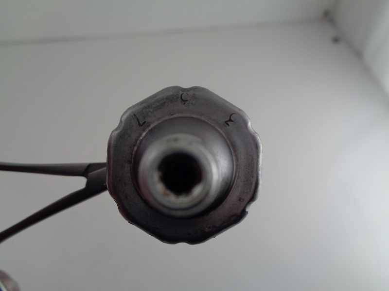 |
Oil Check Valve (77-E87)
See Oil Check Valve (86-E87) in the Sportsterpedia.
The Oil Check Valve on 1986-E1987 engines is located behind the threaded filter adapter in the center of the oil filter mount. The filter adapter I.D. was enlarged on the filter end to accept the check valve. The check valve operation is dependent on receiving filtered oil (through the filter media) to lift the check valve cup and allow oil to pass. Therefore, a stopped up oil filter media condition (not allowing flow or enough flow) may not produce enough oil pressure to open the check valve before the filter bypass opens.
The oil pump check valve plays a role in the operation of the oil pressure switch.
It adds additional restriction in the feed path which raises the oil pressure in the chamber feeding the switch.
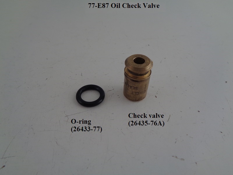 |  |
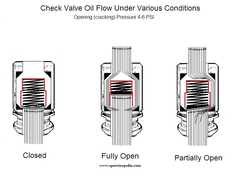
The check valve is not a pass through but instead a cartridge type one way check valve operated by a spring loaded cup against a seat pressing at 4-6 PSI. Oil pressure enters the center of the check valve, lifts the cup against its spring and exits the check valve by pushing around and past the cup and into the engine. At a point, the cup will float off it's seat up against the spring towards the end of it's travel.
According to the FSM, the check valve has two main functions;
It prevents gravity oil drainage from the tank to the engine when not in operation.
It also acts as a restriction to activate the oil pressure switch.
Without the check valve, the pressure would not build up as much in the oil 'pocket' in the filter housing.
It would free flow into the crankcase and disperse. With the check valve installed and the oil having to find it's way around the cup, pressure builds behind it in the pocket. This back pressure builds inside the pump and pushes the pressure switch contacts open, shutting off the oil light.
The check valve spring does not control the amount of oil that enters the engine (unless it's stuck closed). The flow goes past the check no matter what. The spring pressure is very light. It regulates (creates and manages) the oil pressure in the pocket next to the switch before it enters the engine. That pocket is protected for one reason (to operate the oil switch, therefore the oil light). If you are not running an oil light, there is no reason to be concerned with the check valve (in regards to a running engine). You could remove the light and the check and it would not affect the oil flow thru the engine. The positive displacement oil pump will still deliver oil. But you are also running your machine blind.
The check/switch/light is a safety precaution to let you see the light and warn you that the pressure in the pocket is low. In theory and design, if the pressure in the pocket is low, oil flow would also be low. In practice, there are too many variables on a worn engine, pump, check, switch etc. to keep theory and design true all the time. The cup will stay off it's seat and open as long as there is sufficient oil pressure pushing against its spring. This spring actuates the 4-6 PSI pressure that the pump must overcome. If there is not enough oil pressure coming from the pump to keep the check valve cup completely or partially off it's seat; The back pressure from the spring will push the cup toward it's seat, or closed position, equal to the amount of minimum pressure loss from the pump. Thinner (hotter) oil flows faster and builds less pressure.
When the oil thins out, the oil will still push past the cup.
At a point, the pressure from the pump may not be sufficient to completely float the cup off it's seat. So, the cup will turn sideways a bit only allowing oil to pass it on one side.
This reduction in pressure is also sensed by the oil pressure switch. When the pressure drops, the diaphragm eases back toward the closed position. If the pressure is low enough, the contacts will close or partially make contact while closing or intermittently opening and closing. The oil light will come on or flicker depending on the action of the contacts.
The pressure switch requires no back pressure from the engine to stay open. It opens solely from the pressure generated from the oil pump with the assistance of the check valve to hold some of that pressure in the pump.
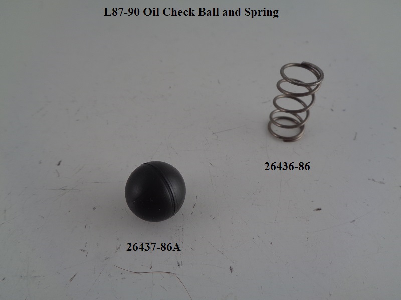
Oil Check Ball (L87 and Up)
Sub Documents
See also L87-90 Oil Check Ball Pics in the Sportsterpedia.
The Oil Check Ball is located behind the threaded filter adapter in the center of the oil filter mount.
The oil pump check ball plays a role in the operation of the oil pressure switch.
The check ball replaced the check valve in L87 and up models.
L87 check ball addition at the oil filter mount. 39)
L87 models were fitted with a (light brown) check ball and spring instead of a cartridge type check valve as in previous year models.
The original check ball was redesigned to a smaller version due to the bore size for it in the filter mount.
The new smaller size ball (26437-86A) was black and usable on 86-90 model Sportsters.
Some Sportster oil filter mounts with the original oil check ball may have had an undersized oil passageway.
The brown check ball was not the problem. 40)
But the original check ball could stick in the undersized oil passage, causing reduced oil pressure and lifter noise.
Rather than changing the oil filter mount, the MoCo chose to reduce the diameter of the check ball.
The solution was to remove the original light brown check ball and either;
Install the new black check ball (26437-86A) and spring (26436-86).
Or, install the old style check valve (26435-76A) and it's O-ring (26433-77).
Affected crankcase numbers:
The oil enters the oil filter at full pressure from the pump. After the oil exits the oil filter, it pushes against and opens the check ball that's located behind the oil filter mount. The spring behind the check ball keeps pressure (4 to 6 psi) against the ball. 41) It's purpose is to prevent the oil tank from draining into the motor while the bike is shut off. It also keeps enough oil pressure upstream of the motor to turn off the oil pressure light. It does nothing to actually regulate the oil pressure in the motor though. 42)
The check ball operation is dependent on receiving filtered oil (through the filter media) to push the ball off it's seat and allow oil to pass. Therefore, a stopped up oil filter media condition (not allowing flow or enough flow) may not produce enough oil pressure to open the check ball path before the filter bypass opens.
 | 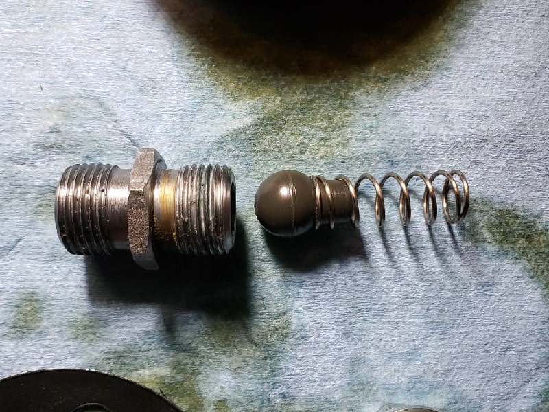 | 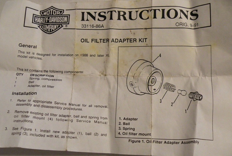 |
| Check Ball (26437-86A) L87-91 (replaced by (26437-86B) ) 43) | Check Ball (26437-86B) 92-Up 44) | Check Ball and Spring Kit (33116-86A) for 86 -up Models 45) |