Table of Contents
This is an old revision of the document!

EVO: Oiling & Lubrication
Engine Oil System
More pathway details at Engine Oil Routes
And in the REF section of the Sportsterpedia, see these:
A good discussion on the XLFORUM including rubbermount crankcase pressure: 04s and up and oil use.
Engine Oil Cycle and Individual Pics
The Sportster Oiling Cycle is defined in the FSMs.
However, that description is vague in some of the intricate transitions of the oil path in the engine.
This article is an attempt to clarify some of the gray areas from the FSM's descriptions with further description and pictures. 1)
General Statement
- The engine has a force-fed (pressure type) oiling system incorporating oil feed and return pumps in one pump body with a check valve on the feed side. 2)
- The feed pump forces oil to the engine to lubricate;
- Lower connecting rod bearings
- Rocker arm bushings
- Valve stems
- Valve springs
- Pushrods and tappets
- Splash and gravity oil from the connecting rods, crankshaft, rocker boxes and head/cylinder drainage holes serve to lubricate;
- Cylinder walls
- Pistons, piston pins
- Cam gears and bushings
- Main bearings
- The scavenge pump returns oil from the bottom of the gearcase and crankcase sump to the oil tank.
91 and up engine oil cycle from the FSMs
- Oil is gravity fed from the oil tank to the oil pump.
Once the oil pump feed gerotors begin spinning, they also pull a vacuum on the incoming oil supply.
The oil pump sends pressurized oil up through a cavity in the filter housing to the oil filter. - Filtered oil dumps into the filter adapter opening a check ball between 4-6 psi. (28-41 kN/m²) into the crankcase feed galley to the tappet blocks and lifters.
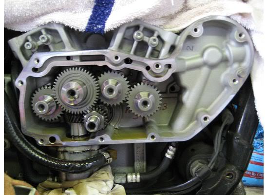
- Cross drilled passages intersect the main feed galley and carry oil to each lifter.
Oil also enters an intersecting passage in the gearcase cover to the crankshaft area via a hole through the pinion gear shaft.
Oil then travels to the right flywheel and routed through the crankpin thus lubricating the rod bearings. - Oil flows up the holes in the pushrods to the rocker arms and shafts.
Oil is supplied to the valve stems via drilled holes in the rocker arms. - The oil then flows off the pushrod side of the heads through the pushrod covers into the gearcase,
lubing the cams and is collected by the scavenge (return) side of the pump. - Oil flows from the rocker area of the heads into the crankcase by way of passages in the heads and cylinders.
Oil in the sump area of the crankcase is splashed onto the pistons, cylinder walls and flywheel components. - Oil collected in the crankcase sump is passage-routed back to the scavenger side of the pump.
(via the ladle, half spoon, duck bill scavenge port protruding from the back of the pump 3) )
It is fed by the scavenging effect of the pump and pressure generated by the downward stroke of the pistons. - Return oil fills a cavity above the pump's return gears which pumps the oil back into the oil tank.
A small amount of oil flows from the feed galley in the right crankcase half through a restricted orifice and sprays oil onto the rear intake cam gear. 4)
Oil Pump Feed
The oil pump is non-regulating and delivers its entire volume of oil under pressure to the oil filter mount.
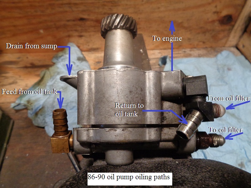
86-90 engines
- Oil is gravity fed to the oil pump from the oil tank.
- Then the oil pump feed gerotors send pressurized oil up through a cavity in the filter housing via an external hose to the oil filter.
- The oil leaves the filter via an external hose and returns back to the oil pump.
- Then it is routed through a check valve or check ball inside the oil pump and into a passage in the cam cover.
| 86-90 Oil Pump Oiling Paths. 5) |
 |
91 and up engines
- Oil is gravity fed to the oil pump from the oil tank.
- Then the oil pump feed gerotors send pressurized oil up through a cavity in the filter housing via an external hose to the oil filter.
- The oil leaves the filter and is routed through a check ball and into the case feed galley.


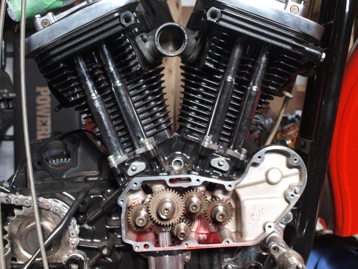
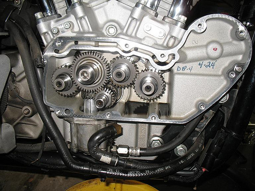
Oil Passages From The Filter Pad
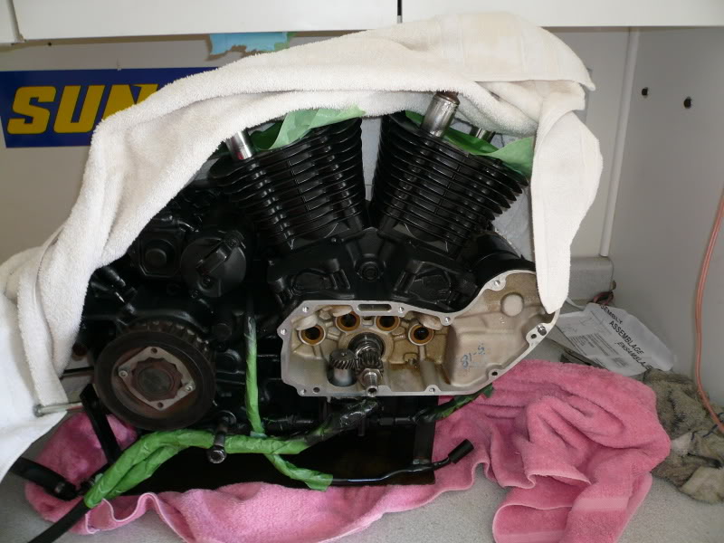
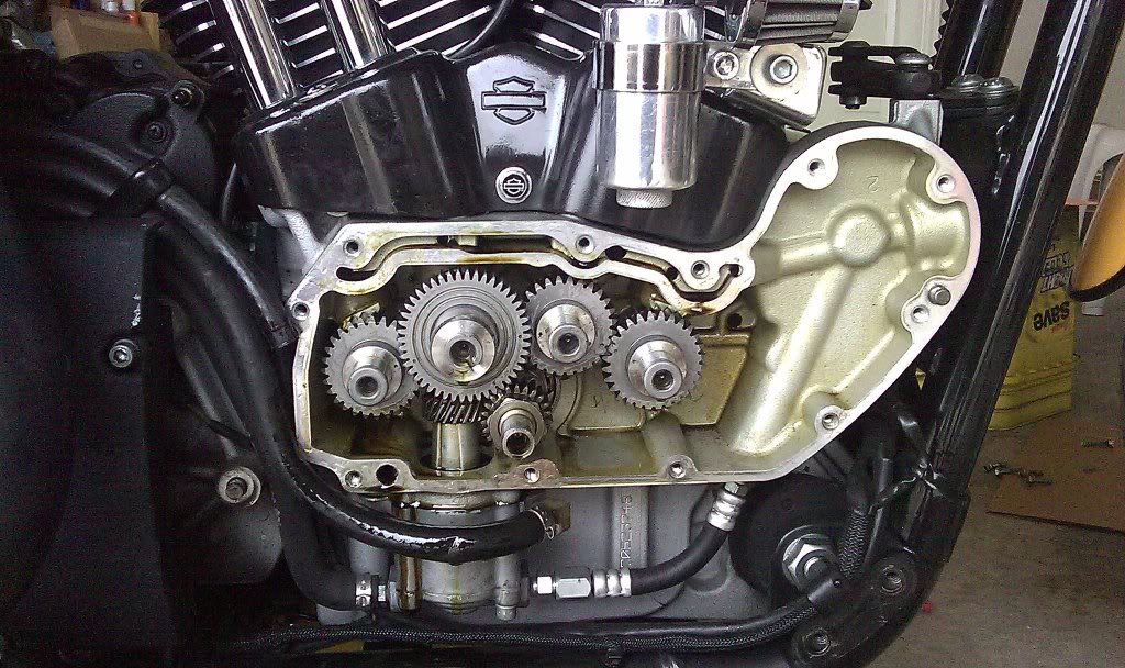
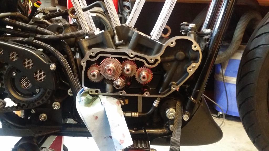
Below are different cam chest pics showing the oil passages from the filter pad.
| 86 Cam Chest 8) |
 |

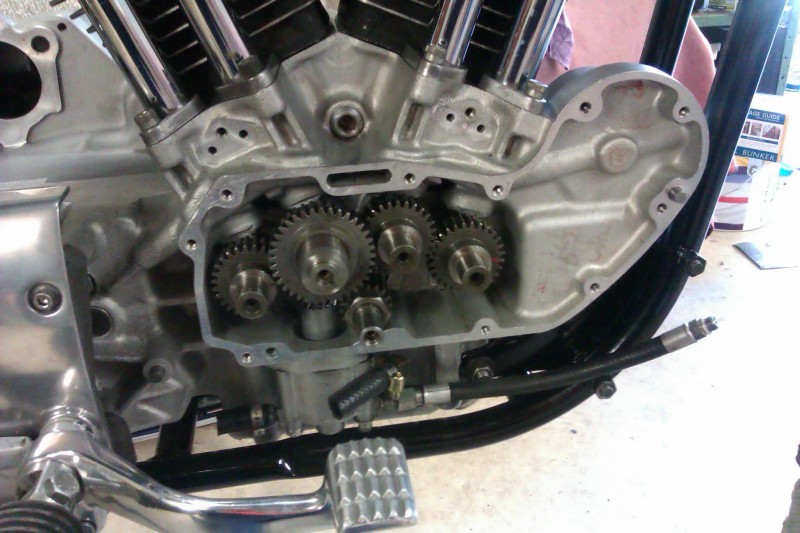

| 2013 Cam Chest 19) |
 |
| XR1200 Cam Chest 20) | |
 |  |
Oil Filter - Function & Control
Also see the REF section on Understanding Oil Filters
- The oil pump sends pressurized oil to the oil filter.
- There are two cavities inside the oil filter.
- Oil enters the outside cavity, passes thru the filter media and exits thru the filter adapter in the center.
86-90 engines
- The filtered oil is sent back to the oil pump.
91 and up engines
- The filtered oil pushes against and opens a check ball in the filter housing between 4-6 psi. (28-41 kN/m²).
- Oil leaves the check ball into the horizontal crankcase feed galley (running along the top of the case beside the tappet blocks and lifters).
General Overview

 A) … Incoming 'Dirty' Oil on Outside of Filter Material (RED color for dirty oil)
B) … Filter Material inside the Oil Filter
C) … Bypass Valve - Passes dirty oil when necessary to prevent oil starvation
D) … Output of Oil from the Filter - (GREEN color for filtered oil - RED for UNfiltered)
E) … Check Valve keeps oil from draining into engine when not running
F) … Oil Supplied to Engine - Could be Clean or Dirty depending on Bypass Valve operation
Sometimes, these exist
G) … Anti-Drain Back Valve in the Oil Filter to prevent the filter being empty
H) … Pressure Relief Valve on 1986-1991 models (in the oil filter mount)
(This overview is not intended to present or explore every detail of any of these parts. See the REF section on Understanding Oil Filters)
The oil pump is hydraulic and moves oil efficiently. It is very strong due to being directly driven and having minimal gear lash in the pump. It will pump forcibly IF NECESSARY. The flow rate capability (GPM) will vary somewhat based on resistance and the efficency of the pump and the level of wear within the gerotor gears.
The pump is capable of 100's of PSI. The amount of oil passed per revolution is nearly constant, thus the GPMs will increase as the RPMs increase.
It is the resistance to flow that will determine the actual pressure (PSI). If there is little resistance, then the PSI pressure will be low. If there is much resistance, the constant force of the pump will create high (or very high) PSI pressure.
The physical hoses & routing (bends/kinks/etc.) will create some resistance (getting to (A)), the filter material (B) will create some resistance, the check valve (E) will create some resistance and the engine oiling system will create some resistance… Of course, the oil temperature affects the viscosity of the oil. Colder Oil = Thicker Oil, which increases the resistance to flow. Combined at any one specific time, these factors create the PSI necessary to push the GPM load that the pump is supplying.
The density of the filter material (B) (microns) & the level of contaminant saturation in the material will affect the resistance. Of course, the level of contaminant saturation varies with usage.
The bypass valve (C) is intended to prevent oil starvation in the engine when the filter passes oil poorly - but to do so, it must pass UNfiltered oil around the filter material. It does this only when the Bypass Valve PSI rating is exceeded. This only occurs when the filter material cannot pass enough oil THRU it, thereby creating a higher oil pressure on the input side (due to filter resistenace to flow). This is sensed by the bypass valve (C), which then opens to continue supplying some oil around (rather than thru) the filter material to keep the engine oiled. Physically, the implemented bypass may be at the top or bottom of the filter, but the function is the same.
The Anti-Drain-Back Valve (G) prevents the oil inside the filter from escaping back out the input side of the filter (A). This maintains an oil reservoir (inside the filter) that is ready to supply the engine immediately on start-up, rather than waiting for new oil to fill the filter cavity once the newly started engine begins to pump oil to the filter.
In a similar way, the Check Valve (E) helps to prevent oil draining out of the filter (or being gravity drained from the oil tank, thru the pump & filter) into the engine oiling system when the active flow stops (engine is not running). It has a very low PSI setting so that even a very low movement of oil will pass thru to begin oiling the engine.
The Pressure Relief Valve (H), which is only on the 1986-91 XL models, is set for about 30psi. This guarantees that the pressure to the oil filter is below that level. But that level of pressure is only present when the oil is cold. Once warm, the normal pressure is below 30psi all the time, even at high RPMS 21)
While both are differential valves, the Filter Bypass Valve (C) functions on a difference in pressure from one side of the filter material to the other side, while the Pressure Relief Valve (H) functions on absolute input pressure because there is no pressure on the other side of it (in the gearcase or crankcase).
The Bypass Valve (C) functions differentially because there is supplied oil (under pressure) at both sides of the valve - One side is supplied from the outside of the filter material and the other side is supplied pressure from the oil that has passed thru the filter material (being at the outlet of the filter). This means IF the filter material flows well (being new and/or clean with warmed up oil viscosity) then both sides of the material will be close to the same pressure level, with the material presenting little resistance. BUT, if the filter is very restrictive (clogged or oil is cold & thick) the flow from passing THRU the filter will be present a significantly less pressure on the Bypass Valve output side, thereby calling for the Bypass Valve (C) to open.
To be clear, the Bypass Valve (C) doesn't care if there is 5psi on each side or 20psi on each side, it will not open until there is a difference between the incoming side of the filter & the outgoing side of the filter. If rated at 12psi, the difference must be 12psi before it opens (17psi in vs 5psi out -or- 32psi in vs 20psi out). If so rated, the difference must be 12psi. This can/will occur when the oil is cold & thick or when the filter is sufficiently clogged to minimize oil flow thru it.
In contrast, there is no pressure on the output side of the Relief Valve (H). It only has pressure on the input side, which, when it reaches 30psi, will open to allow some volume to bleed off, thereby reducing the pressure in the line. Since there is no pressure on the output side of the Relief Valve (H), dumping into the gearcase or crankcase, the differential pressure is always perceived as XX (inside) psi to 0 (cam/crank) psi.
It should also be noted that in normal operation, the bypassing of the oil filter for brief periods (like thick viscosity) will have little affect on the longevity of the engine. However, a clogged oil filter that is continuously bypassing oil around the filter material, will eventually sufficiently contaminate the engine oiling system to cause damage. Oil filter replacement on the recommended schedule (or sooner) is a precautionary chore to keep the engine supplied with clean oil.
These two references are a good read:
http://www.mgnoc.com/article_oil_filters_revisited.html
http://xlforum.net/forums/showthread.php?t=2071942
Oil Filter Mount
Sub Documents
—– 1986-1990 Models —–
—– 1991-later Models —–

The oil filter adapter is the threaded part that the filter screws onto.
The threads on the adapter for the filter are 3/4“-16.
- - - - - - - - - - - - - - - -
See also Oil Filter Fitment in the REF section of the Sportsterpedia.
Engine Oil Pressure
The oil pump is non-regulatory and delivers its entire volume of oil under pressure to the oil filter mount.
When an engine is cold, the engine oil will be more viscous (ie., thicker).
During start-up of a cold engine, oil pressure will be higher than normal and oil circulation will be somewhat restricted within the oiling system.
As the engine wams to normal operating temperature, the engine oil will warm up also and become less viscous - oil pressure will decrease.
When an engine is operated at high speeds;
The volume of oil circulated through the oiling system increases, resulting in higher oil pressure.
As engine speed is reduced, the volume of oil pumped is also reduced, resulting in lower oil pressure.
On 86-91 engines:
Oil pressure was measured with a pressure gauge at the plug hole on the engine case between the tappets.
The 1/8“ NPT allen head plug between the tappets has to be removed for the gauge to be installed.
Note: On 86-90 models, oil pressure (when checked at the oil filter pad) will be 6-10 psi higher than when checked at the tappet plug on the case at idle.
On 92 and up engines:
Oil pressure was measure with a pressure gauge at the oil pressure switch location at oil filter pad.
The oil pressure switch has to be removed for the gauge to be installed.
(idle speed varies from 950-1050 rpm between the different FSMs)
2013 XR1200X: 23)
Includes an oil cooler with a thermostat that starts to open at 190ºF (88ºC).
The oil pump and the head breathers are a new design.
The oil pump rotors are driven by the cams, the feed rotor is driven off the front intake cam and the scavenge rotor is driven by the rear exhaust cam.
Oil pressure relief (50 psi)
Oil Tank Pressure
See the full article, Oil Tank Pressure, in the REF section of the Sportsterpedia.
There should not be any noticeable pressure in the oil tank.
During normal operation;
With the tank cap / dipstick removed, tank pressure is vented to atmosphere from the top of the tank.
With the tank cap / dipstick installed, tank pressure is vented to the cam chest.
During shutdown;
The oil tank vent is connected to the cam chest and the cam chest is vented out the breather valve in the cam cover.
So if you have pressure in your oil tank and the vent to the cam chest is not blocked then the cam chest is also pressurized.
If the cam chest is holding pressure, then your breather valve can not be venting properly.
Bottom line is that if the vent system is working properly, you shouldn't have excessive pressure build up in the oil tank. 24)
Checking oil pressure
See also Installing an Oil Pressure Gauge in the REF section of the Sportsterpedia.
- Remove the oil pressure switch or tappet hole plug (respectively) and insert the appropriate gauge and fitting(s).
- Run the engine until oil reaches normal operating temperature
(motorcycle should be driven at least 20 miles at or above 50mph).- For an accurate reading, engine oil should be at normal operating temperature: 230°F (110°C).25)
- Check pressure against the figures in the FSM as in below:
Expected (hot) oil pump pressure per the FSM's:
| With pressure gauge mounted at tappet hole plug | ||
|---|---|---|
| Year Model | Minimum PSI (Idle Speed) | Normal Riding Conditions (2500 rpm) |
| 1986-1990 26) 27) | 1-7 psi | 5-30 psi (2500 rpm) |
| 1991 28) | 7-12 psi | 12-17 psi (2500 rpm) |
| With pressure gauge mounted at oil filter pad | ||
| Year Model | Minimum PSI (Idle Speed) | Normal Riding Conditions (2500 rpm) |
| 1986-1990 29) | 7-17 psi (see above) | not specified |
| 1992-2004 30) 31) 32) 33) 34) 35) 36) | 7-12 psi | 10-17 psi (2500 rpm) |
| 2013 XR1200X 37) | 16-20 psi | 40-44 psi |
Rocker box pressure
- Residual working pressure from the lifters resides in the rocker boxes as well as crankcase pressure.
- On a cold startup, the pressure is higher due to the thicker oil present.
- As the engine warms up, the oil thins out and the pressure is reduced in the rocker boxes.
- Excess crankcase pressure (air and oil mist) is vented differently between (86-90) and (91 and up) models.
- So, it is possible to notice different pressures from them with a pressure gauge testing from the rocker box.
- However, a gauge tapped into any rocker box will most likely measure air pressure instead of oil pressure.
- Air will compress and oil will not, therefore the readings should be lower than if you were testing at the oil pressure switch.
86-90 engines
- Crankcase pressure is vented through the cam cover.
91 and up engines
- Crankcase pressure is routed up the pushrod tubes and exit a hole in each head on the intake valve side.
Cam Cover Pressure
Oil pump pressure is always present in the cam cover with the engine running.
That is also a deceiving statement. Pump pressure runs through internal cavities in the cover to get from the top to the bottom of the cover and to the pinion shaft.
However, oil pump pressure does not dump directly into the cam chest from the cover.
86-90 engines
- Oil pressure to the cam cover is fed from the bottom.
- The cover gets it's oil from the oil pump via intersecting holes between the bottom of the case and the cover.
(the gearcase gets no oil from this passage in the cover, outside of spill from the pinion shaft bushing)
- The cover supplies oil to the feed galley for the lifters.
- A hole is internally routed from the top to the bottom of the cover with a hole exiting in each corresponding hole in the case.
- The hole in the middle of the case at the top intersects into the internal oil feed galley.
- It also supplies oil to the pinion shaft and bushing.
- An internal cross drilled hole runs to the back of the pinion shaft bushing.
- This oils the pinion bushing and at the same time sends pressurized oil through the hole in the pinion shaft for the rod bearings.
91 and up engines
- Oil pressure to the cam cover is fed from the top.
- Oil is sent though a cross drilled hole from the case feed cavity into the top of the cam cover to the rear of the pinion shaft bushing.
(the gearcase gets no oil from this passage in the cover, outside of spill from the pinion shaft bushing)
- The cam cover supplies oil to the pinion shaft and bushing.
- An internal cross drilled hole runs to the back of the pinion shaft bushing from the slotted cavity in the top of the cover.
- This oils the pinion bushing and at the same time sends pressurized oil through the hole in the pinion shaft for the rod bearings.
Oil System Controls
Oil Pressure Regulator - 1986-1991 Models ONLY
—– 1986-1990 Models —–
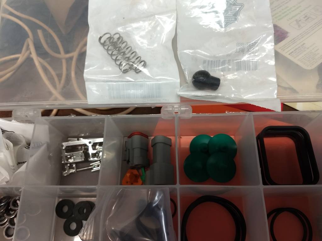
See pics and installation of the plunger and spring for 86-90 models in the Sportsterpedia.
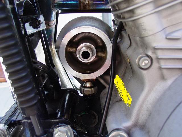
 |
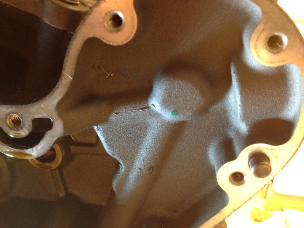
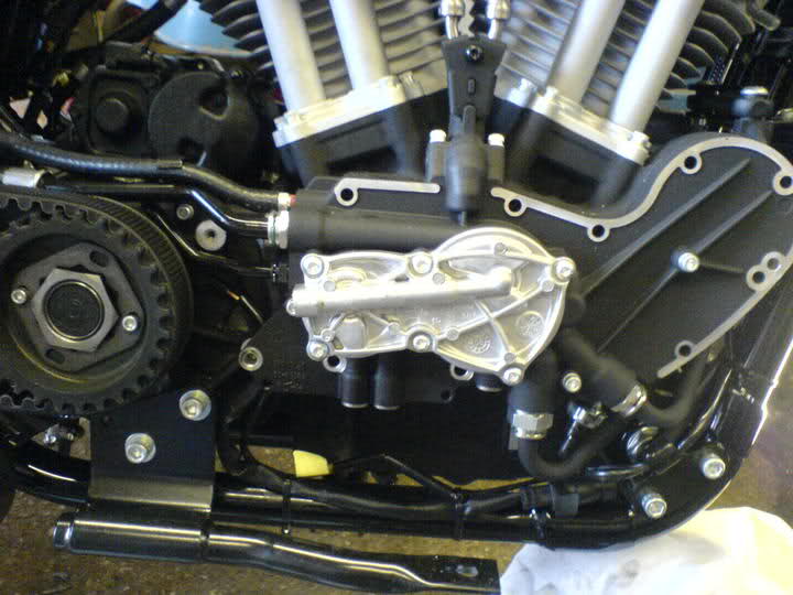
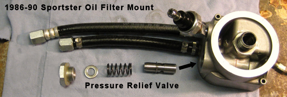
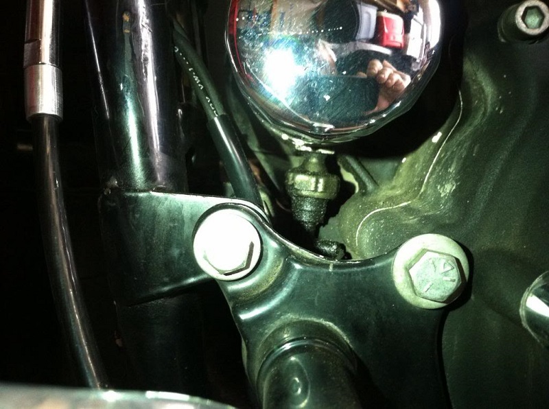
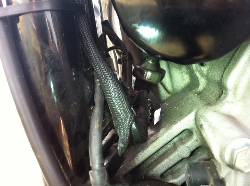
| 1986-90 Oil Filter Mount 38) | Pressurized oil comes into the gearcase from the hole at the arrow on the right. 39) |
 |  |
With the new Evolution engine in 1986, an oil pressure regulator (relief valve) was implemented to bleed off some of the oil when the pressure thru the filter became to high.
The spring loaded pressure valve was built into the oil filter mounting pad.
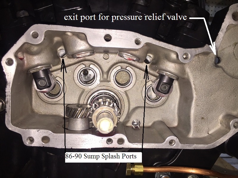
There is a passage from the filter pad relief valve into the cam gearcase.
The discharge from the relief valve drains down to the crankcase sump through a hole in the case wall and gets pumped back to the tank.
The spring-loaded pressure regulator opens at about 30 psi.
However, it is usually only regulating when the engine oil is cold.
When the engine is warm, the valve is typically shut, since pressure is usually below 30 psi even at high rpms. 40)
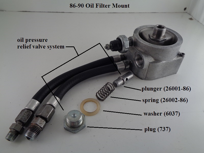
The pressure relief parts for 1986-1990 are:
| HD Part# | Description |
| 737 | PLUG |
| 6037 | WASHER |
| 26001-86 | PLUNGER |
| 26002-86 | SPRING |
The plug installation torque is 15-20 ft-lbs.
—– 1991 Model —–
In 1991, the entire oil filter mount was incorporated into the right crankcase half. It still used a supply & return hose to flow oil thru the filter.
The implementation of the pressure regulator in this version used the same spring & plunger as before. It was mounted into a hole from the gearcase side of the mount. Then, a new plug, with a hole drilled in the center of the hex head, held the spring & plunger in place. This allowed oil to escape from the incoming side of the filter, thru the plug hole and into the gearcase, where it eventually made it to the crankcase sump & was returned to the oil tank.
As in the previous implementation, this allowed the relief valve to bypass oil thru the plunger when activated instead of pumping it thru the filter. The relief pressure was the same, being about 30psi.
Since the new plug is already in the gearcase, the washer (6037) was eliminated.


The pressure relief parts for 1991 are:
| HD Part# | Description |
| 742 | PLUG |
| 26001-86 | PLUNGER |
| 26002-86 | SPRING |
(It should be noted that the 1991 & 1992 parts catalogs list these pressure relief parts for all models, although they are not illustrated for either year. However, I have only been able to visually verify the existence of these parts on the 1991 model engine. Harley Tech Tips #26 & #27 seem to support this, but there might have been some early 1992 models with the 1991 implementation. Research continuing.)42)
XLFORUM Discussion Threads on the Pressure Regulator
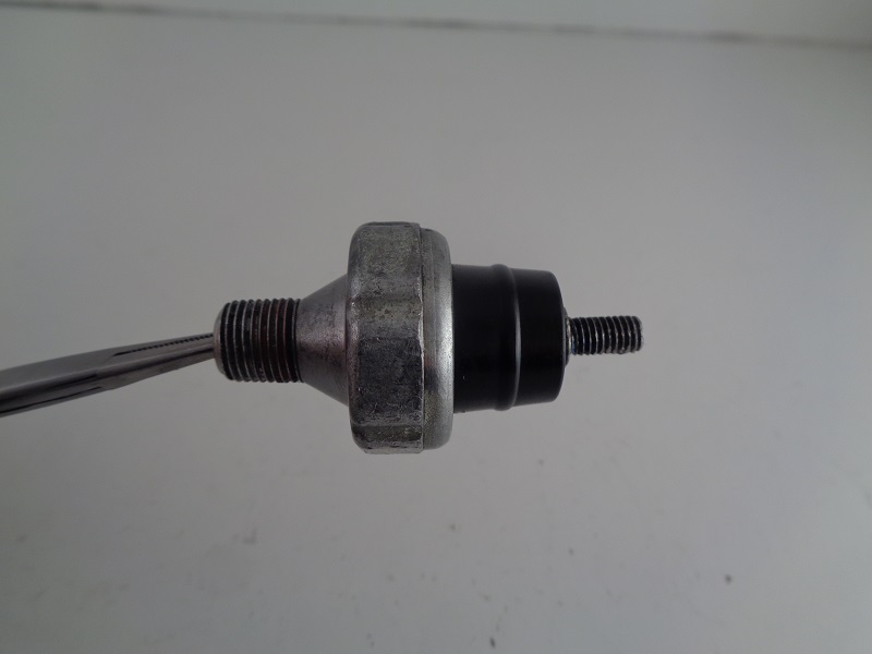
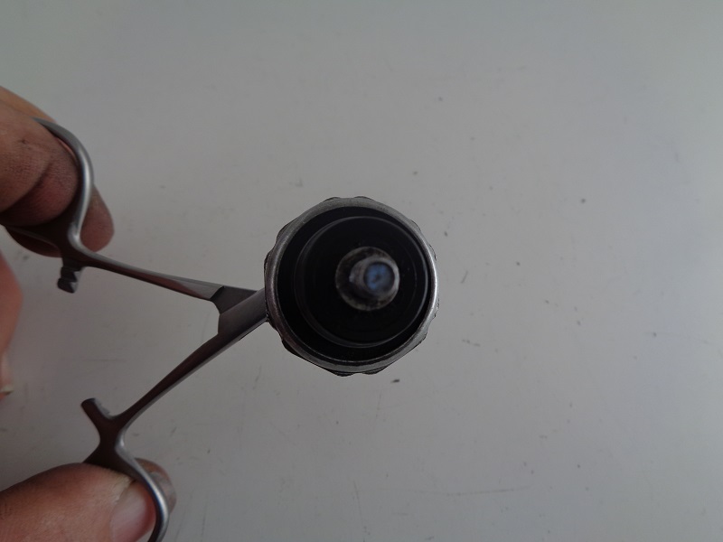
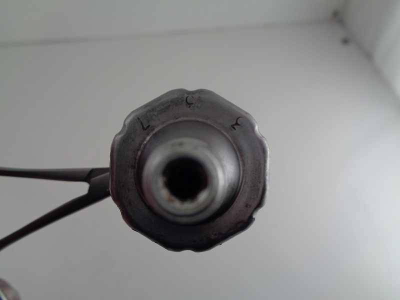
Oil Pressure Switch
See also Testing the Oil Pressure Switch in the Ref section of the Sportsterpedia.
The oil pressure switch (for the oil light) is a pressure actuated diaphragm type on / off switch basically.
The diaphragm is spring loaded and held against its contact point when then engine is not running or the when the oil pressure is too low while running.
With the switch contacts touching, this closes the circuit to the oil pressure light and causes it to light up (with the key on, of course).
When the engine is fired up, oil pressure builds in the filter pad, activates the oil light switch and opens the oil pump check valve (or check ball respectively) allowing oil to enter the engine.
Oil pressure is sensed by the oil pressure switch.
By the time the engine reaches over 1000 to 1200 rpms, the oil pressure is sufficient to move the oil pressure switch diaphragm completely off it's seat.
This opens its contact point, breaking the circuit to the oil pressure light and it goes off.
Cold cranking oil pressure can reach between 30 PSI and upwards of 60-100+ PSI.
Oil pressure will vary under normal riding conditions. See above for expected oil pressures.
However, idle (hot) oil pressure will vary from 7-17 PSI on most models.
So, at idle, the oil check valve (or ball) may only be opened just past it's cracking pressure (not to it's end of travel).
In the Case of a Defective Oil Pressure Switch:
This switch opens and closes the contacts to the oil pressure light.
The oil light is important to have since if it is not working, it can be assumed that you have little to none oil flow to the engine.
If the pressure switch doesn't operate the light it should be checked for proper operation or replaced.
For the $30 or whatever you save by not buying the switch, it's just not worth it to not have the low engine pressure idiot light working. 43)
If your motor is ready to run and you need to test it then you can connect a piece of clear hose so you can see oil in it.
Don't plug the end till you've primed the pump (if applicable).
Replace a defective switch as soon as possible.
Torque:
Pressure switch: 5-7 ft/lbs.
Wire nut: 4-10 in/lbs.
| Oil pressure switch 44) | ||
 |  |  |
Oil Pressure Light
If the oil pressure light stays on at speeds above idling, always check the oil supply first.
Then if the oil supply is normal, look inside the oil tank to determine if oil is returning to the tank from the return hose with the engine running.
If oil is returning to the tank, there is some circulation and the engine may be run a short distance if necessary.
If no oil is returning, shut the engine off until the trouble is located and fixed.
Conditions causing the oil light to stay on;
Low or diluted oil supply,
Or a plugged lifter screen (86-91) under the plug between the tappets,
A grounded oil signal switch wire,
Faulty oil switch,
Faulty or weak oil pump,
Clogged feed hose (in freezing weather from ice and sludge preventing the circulation of oil).
Oil Check Valve (77-E87)
See Oil Check Valve (86-E87) in the Sportsterpedia.
The Oil Check Valve is located behind the threaded filter adapter in the center of the oil filter mount.
The filter adapter I.D. was enlarged on the filter end to accept the check valve.
The check valve operation is dependent on receiving filtered oil (through the filter media) to lift the check valve cup and allow oil to pass.
Therefore, a stopped up oil filter media condition (not allowing flow or enough flow) may not produce enough oil pressure to open the check valve before the filter bypass opens.
The oil pump check valve plays a role in the operation of the oil pressure switch.
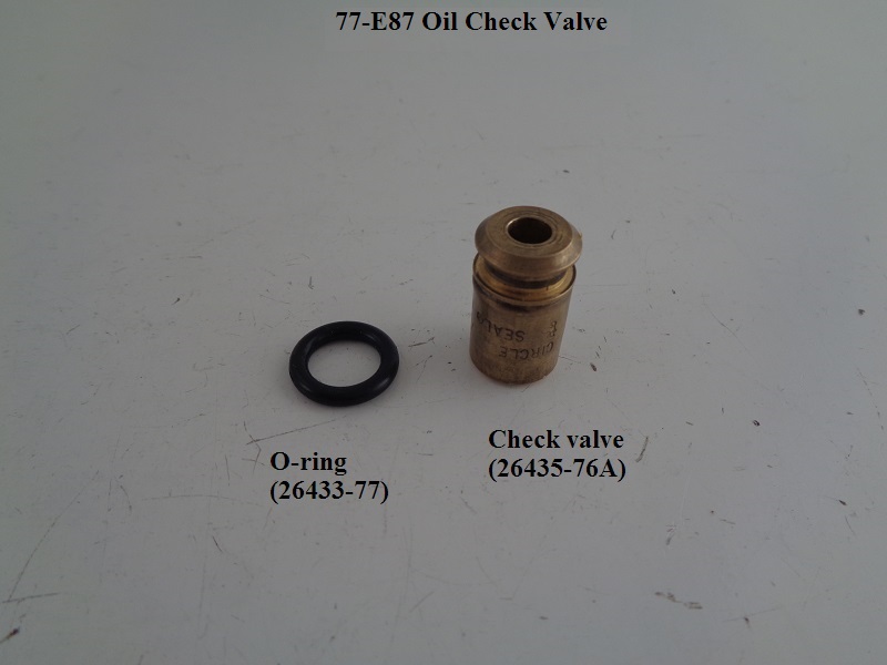 |  |
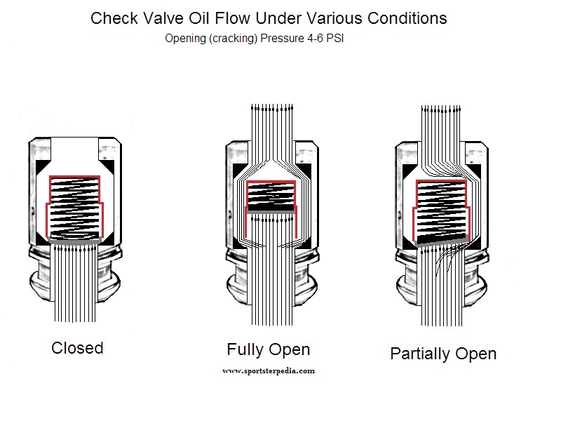
The check valve is not a pass through but instead a cartridge type one way check valve operated by a spring loaded cup against a seat pressing at 4-6 PSI.
Oil pressure enters the center of the check valve, lifts the cup against its spring and exits the check valve by pushing around and past the cup and into the engine.
At a point, the cup will float off it's seat up against the spring towards the end of it's travel.
According to the FSM, the check valve has two main functions;
It prevents gravity oil drainage from the tank to the engine when not in operation.
It also acts as a restriction to activate the oil pressure switch.
Without the check valve, the pressure would not build up as much in the filter pad.
It would free flow into the crankcase and disperse.
With the check valve installed and the oil having to find it's way around the cup, pressure builds behind it.
This back pressure builds inside the filter pad and pushes the pressure switch contacts open, shutting off the oil light.
The cup will stay off it's seat and open as long as there is sufficient oil pressure pushing against its spring.
This spring actuates the 4-6 PSI pressure that the pump must overcome.
If there is not enough oil pressure coming from the pump to keep the check valve cup completely or partially off it's seat;
The back pressure from the spring will push the cup toward it's seat, or closed position, equal to the amount of minimum pressure loss from the pump.
Until the seat is fully closed, the remaining oil pressure will still try to push past the cup.
At a point, the pressure from the pump will not be sufficient to completely float the cup off it's seat.
So, the cup will turn sideways a bit only allowing oil to pass it on one side.
This reduction in pressure is also sensed by the oil pressure switch.
When the pressure drops, the diaphragm eases back toward the closed position.
If the pressure is low enough, the contacts will close or partially make contact while closing or intermittently opening and closing.
The oil light will come on or flicker depending on the action of the contacts.
The pressure switch requires no back pressure from the engine to stay open.
It opens solely from the pressure generated from the oil pump with the assistance of the check valve or check ball to hold some of that pressure in the filter pad.
So, it is possible but not likely to have a stuck closed check valve with no oil light on.
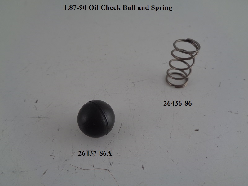
Oil Check Ball (L87 and Up)
See also L87-90 Oil Check Ball Pics in the Sportsterpedia.
The Oil Check Ball is located behind the threaded filter adapter in the center of the oil filter mount.
The oil pump check ball plays a role in the operation of the oil pressure switch.
The check ball replaced the check valve in L87 and up models.
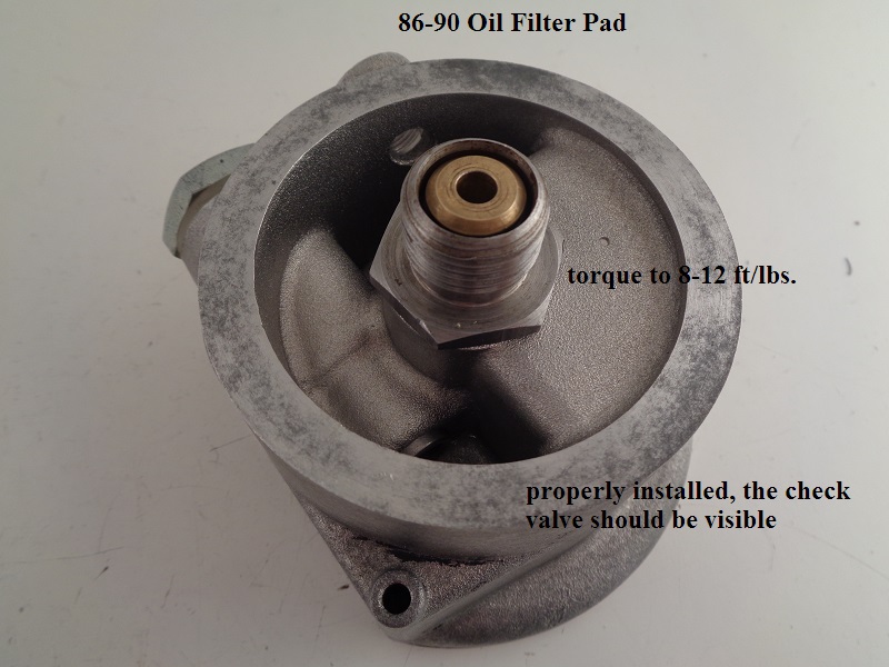
L87 check ball addition at the oil filter mount. 48)
L87 models were fitted with a (light brown) check ball and spring instead of a cartridge type check valve as in previous year models.
The original check ball was redesigned to a smaller version due to the bore size for it in the filter mount.
The new smaller size ball (26437-86A) was black and usable on 86-90 model Sportsters.
Some Sportster oil filter mounts with the original oil check ball may have had an undersized oil passageway.
The original check ball could stick causing reduced oil pressure and lifter noise.
The solution was to remove the original light brown check ball and either;
Install the new black check ball (26437-86A) and spring (26436-86).
Or, install the old style check valve (26435-76A) and it's O-ring (26433-77).
Affected crankcase numbers:
The oil enters the oil filter at full pressure from the pump.
After the oil exits the oil filter, it pushes against and opens the check ball that's located behind the oil filter mount.
The spring behind the check ball keeps pressure (4 to 6 psi) against the ball. 49)
It's purpose is to prevent the oil tank from draining into the motor while the bike is shut off.
It also keeps enough oil pressure upstream of the motor to turn off the oil pressure light.
It does nothing to actually regulate the oil pressure in the motor though. 50)
The check ball operation is dependent on receiving filtered oil (through the filter media) to push the ball off it's seat and allow oil to pass.
Therefore, a stopped up oil filter media condition (not allowing flow or enough flow) may not produce enough oil pressure to open the check ball path before the filter bypass opens.