Table of Contents
This is an old revision of the document!

IH: Carburetor, Intake Manifold & Exhaust - Sub-01R
Keihin Butterfly Carb (non CV) Functions, Adjustments, Tuning
For Late 1976-1987 Sportsters.
If you are opening up your carb for the first time, you need three things:
- A FSM (Factory Service Manual) for you year model.
- A factory Parts Catalog.
- A good rebuild kit (new rubbers all through a carb make a big difference to it's performance)
The L76-78 Keihin butterfly carbs worked the best and had more adjustment to them. 1)
They had no choke cam, a deeper frost plug in the top and a wider range in them.
Another factory fix was to seal the frost plug in the top with silicone to be sure they weren't leaking.
To find out which later carb you have;
On 79 or later Keihin butterfly carbs, measure the venturi. 34mm = Sportster, 38mm == big twin. 2)
You can cut two pieces of cereal/Kleenex box cardboard, 34mm and 38mm wide and each a few inches long each.
See which best fits the most narrow part of the venturi.
Service Bulletin Information
Lean Condition Adjustments from the MoCo (1979)
- During the mid 1979 model season, HD makes a recommendation to dealers for corrective measures regarding the carburetion and ignition system on (1100, 1200 and 1340cc) models with emissions control design changes. They operate with leaner air/fuel mixtures and are more sensitive to carburetor mixture settings / ignition spark. 3)
- For proper carburetion it is recommended to check the following items as corrective measures for irregular running and spit-back which are symptoms of an excessively lean mixture. Also check for proper ignition.
- Check to see that the intake manifold seals and band clamps are installed properly. Using a squirt can with stanisol or kerosene, squirt some on these connections with the engine idling and see if there is any change (increase or decrease) in RPM which would indicate an air leak.
- The air cleaner backing plate must be flat against the carburetor flange gasket surface and the air cleaner mounting brackets must be adjusted and tightened properly per the FSM with no air leakage at the carburetor mounting flange.
High Altitude Modification Kit
- Carburetor modification kits (including jet(s) and an accelerator pump stop screw) were made available for 1200cc, 1340cc and 1000cc models to provide leaner fuel mixtures when operating at elevations above 4000 feet sea level. 4)
- Normally, leaner fuel/air mixtures are required for proper engine operation as the elevation above sea level increases. This high altitude kit (27096-79 for 1979 XLH (XL), XLCH, XLCR-1000) should be installed where there is evidence of a rich condition causing loss of smooth combustion, stumbling on acceleration or such other carburetor issues at high altitudes.
- The kit for Sportsters includes a #160 main jet, accelerator pump stop screw and the front down tube on the frame.
- Install and adjust the acc pump stop screw to extend 1/8“ past hole in lever.
- Note, any motorcycle modified for high altitude operation must be converted back to standard if operated at altitudes below 4000 feet. An overly lean condition can cause engine damage.
Idle Speed and Air/Fuel Mixture
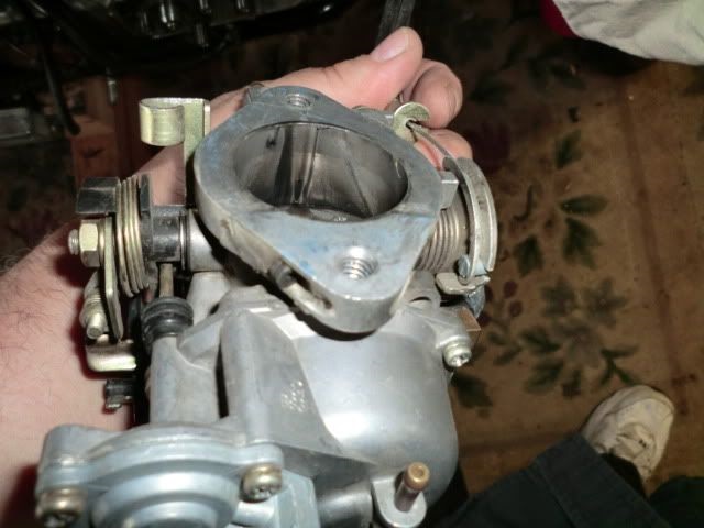
The carb shown is the (L76-E78) 38mm Keihin carb. 5)
Later models run a 34mm with slightly smaller jets but the principles are the same.
The idle mixture adjustment screw.
The -78 FSM specifies to turn it in until it seats gently and then screw it out 7/8 of a turn.
Screwing it in further leans the idle mix while screwing it out richens the mixture.
Sometimes this screw is called the pilot screw, and the idle mixture is called the pilot mixture. (mostly in the UK and former colonies).
The idle speed adjuster.
It is just a butterfly stop screw.
Don't set idle speed too low. It chumps out bottom end bearings and can cause hesitation when you open the throttle.
By ear, idle as slow as it will go, then speed it up a healthy bit.
The usual method to set idle mixture/speed is:
- Set idle MIXTURE screw to 7/8 turns out. Get the bike hot. Set idle at comfortable speed with the idle SPEED screw.
- Adjust the idle MIXTURE screw to the point where engine runs the fastest. This is optimum mixture.
- Adjust idle SPEED screw again to get desired idle speed.
Observations from Hopper of the XLFORUM: 8)
I have found that the spring on the idle speed screw tends to creep the idle speed back up if you try to adjust the idle just that little bit slower.
So, I adjust the idle speed screw right down too slow, then nudge it up slightly faster until I get the speed I want, then it stays there.
According to Joe Minton’s article, and I have found this to be true on my bike:
This is real important. It also is the way to stop “carb farts” – spitting back or backfiring through the carb.
If your Ironhead has aftermarket free-flowing exhaust and an air filter on it,
It will almost certainly need a larger low speed fixed jet, and most likely a bigger main jet too.
But it is the low speed jet that affects the dreaded carb farts.
Main jet affects mixture at wide open throttle and if left lean can overheat the engine, or burn holes in pistons. \\
Low Speed System
The low speed system affects idle up thru about half throttle (idle, low and intermediate speeds when the throttle valve is closed or only partially open). 9)
At idle, fuel enters the main jet where it is metered and enters the slow jet where it is metered again.
Then fuel enters the slow jet bleed tube to mix with air from the slow air passage.
The fuel mixture is regulated by adjusting the low speed mixture screw.
When the throttle valve is closed, fuel mixture flows into the venture mostly through the idle port.
As the throttle valve gradually opens, fuel mix discharge is transferred to the bypass. So the slow jet bleed tube is actually part of the slow jet.
Air/Fuel Mixture Adjustment
Low speed mixture screw:
Other names include the idle mixture screw or the pilot screw.
10)
You may get smoother running by adjusting the this screw. It's on the top of the carburetor. This adjusts the flow of gasoline at idle. 11)
To adjust the low speed mixture screw (screw is held in place by the spring).
- Turn the screw in (clockwise) until lightly seated (do not over-tighten), then back it out 7/8 turns. 12)
From there;- Turning the screw in (clockwise) leans the mixture.
- Turning the screw out (counter-clockwise) richens the mixture.
| Low Speed Mixture Screw: 13) |
 |
Further explanation from IronMick of the XLFORUM
If the carb is old and dirty the pilot screw passage may be gummed up such that you will not be able to “gently seat” the pilot screw reliably. 14)
If this is the case remove the carb from the bike and clean it up. Some guys try to do carb work with the carb in the bike. This is generally a very bad idea.
In the pilot screw passage there should be, in this sequence: screw, spring, washer, o-ring.
Often, POs have installed these parts in the wrong sequence; remember that the purpose of the washer is to protect the O-ring from being damaged by the spring.
The screw usually comes out easily. The other parts may require some work.
The best technique is to stick a pipe cleaner in the hole, twist it around, and, like magic, out come the other parts on the end of the pipe cleaner.
Note: 1966 to 1978 Sportster carbs do not have the O-ring and washer in the pilot screw passage.
Loosen the front fuel tank mount bolt, remove the rear fuel tank mount bolt and prop the rear of the fuel tank up on a piece of 2×4.
(on some bikes this will not be necessary)
Count the number of 1/4 turns as you do it; write the number down. Back it out to the original setting. You may need to return reliably to this setting after experimenting.
The “normal” starting point for this process is 1-1/4 turns out (according to the 79-85 FM) or 1-1/2 turns out (according to usual practice).
Note: An old HotXL magazine article recommends for Keihin butterfly carbs between 1/4 and 1-1/4 turns out.
My experience is that this works best. If you are more than 1-1/4 turns out, your pilot jet is too small.
You want it to be idling at the slowest speed that is consistent with a smooth idle so that you can hear or feel slight changes.
Count the number of 1/4 turns as you do this.
Then turn the pilot screw out counter clockwise until the engine idle gets good, then becomes worse, tending to stall.
Count the number of 1/4 turns as you do this.
The FSM says to use the leanest setting (most screwed in) consistent with a good idle quality.
Some guys say to go between the two settings.
It should be between 1/2 and 1-1/2 turns out from gently seated. If it is not within this range you should change the slow jet.
Hopefully the plugs will come out a nice medium gray or tan color. If they are too dark you can screw it in another 1/4 turn; too light screw it out 1/4 turn, and try the ride again.
For example, too light might mean an intake or exhaust leak, and too dark might mean the pilot jet is too large (among other possibilities).
Idle Speed Adjustment
Adjust the throttle stop screw to make the engine idle at the desired speed with the throttle closed. 15)
It adjusts the movement on the return of the throttle cable. 16)
- Turning the screw clockwise opens the throttle plate (faster idle)
- Turning the screw counterclockwise closes the throttle plate (slower idle)
- Notes:
- Never set idle adjustment to the lowest possible speed. An extremely low idle causes bearing wear oil consumption and slow speed acceleration.
- Recommended idle speed is 700-900 RPM. 17)
- Make final adjustment on low speed screw after the engine is at operating temperature.
- Turn screw in and then out to see if the engine picks up speed or runs smooth.
- Both startup and overall performance will be better with the mixture set slightly on the rich side.
- Readjust the throttle stop screw as needed to get the correct idle speed.
Slow Jet
Other notable names include the pilot jet or idle jet.
Rubber bung:
76-78;
The very first 1976 style Keihin carbs do not use the rubber plug beneath the slow jet. 18)
They do not have the tiny hole going sideways through the carb body from the slow jet housing to the main jet housing.
So they need to suck gas up direct from the float bowl though the exposed slow jet. The slow jet a 100 and the main is a 145.
Check if your carb has that small hole drilled in the body.
If you look down into the hole where the slow jet sits it will be visible in the wall on the side where it can lead to the main jet.
If it does not have that hole, that carb does not use the rubber plug and can cause you to have to screw the idle mix too far open.
79-Up;
The slow jet is under the rubber bung in the pic below. You take out the rubber bung, then unscrew the small brass jet with a screw driver that is a tight fit. 19)
You might have to grind the sides off a screwdriver to get it to go up inside the hole to the jet.
The rubber bung is essential. The bike will run really rough if it comes loose or falls out.
Looking at the carb upside down the passage will be drilled below the main jet and above the pilot jet. 20)
With the plug is installed, the pilot draws fuel through the main jet.
You must run with the plug in place or the main jet will be bypassed by the drilled passage and it will run very rich.
Sometimes, the black plug in the low speed jet is too long and should be trimmed off to allow more fuel in the low speed side. 21)
Trim off as much as needed to still hold it in without falling out about 1/8”. This was a factory fix.
Screaming Eagle Keihin carbs do not use the rubber bung
Slow jet:
If you have anything other than factory original exhaust and air filter, you will most likely need to go up one or two sizes in slow speed jet.
If your idle mixture screw works best more than 1-1/4 turns open, you need a bigger low speed jet.
If your bike spits back through the carb at all, you need a bigger low speed jet.
If your slow jet is too small, the engine misfires on acceleration. 22)
Click here for Keihin butterfly carb standard jet sizes installed in Sportster carbs in the Sportsterpedia.
Fitting an 80 model carb, for instance, will make it run much better. Later 79-onwards and those with 34mm carbs have smaller jets.
JP Cycles and others sells a range of jets so you can take them up in small increments until you get it right.
The smaller jets on the later models seem to come in smaller increments.
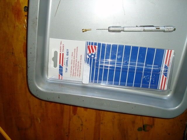
You can drill the low speed jet out from 75 to 80 using a set of jet drills.
You drill the jet very carefully, one size at a time by hand, twirling the jet down over the drill gradually.
Do not use an electric drill, it will make a big hole and possibly break the drill bit.
Buy 2 small jets, and a good drill index (number, letter, fractional or the metric equivalent). 23)
Drill out the small jet one size at a time until you become too rich. Drill out the remaining jet 1 size down.
The right size slow speed jet is the most important factor in getting a good idle, starting, running up to half throttle and stopping carb farts.
Off Idle - Bypass Ports
Another thing that affects low speed running, mostly as you crack the throttle open from idle, is the bypass ports.
This is a row of four tiny holes in the top of the carb, just in front of the idle mixture hole, directly below the idle mixture screw.
As the throttle butterfly opens, each of these extra holes is progressively uncovered by the butterfly and fuel begins to flow out of it.
So as the throttle opens from idle, more gas is allowed in to match the extra air flowing in.
Make sure these holes are not plugged with gunge. Take out the idle mixture screw and squirt carb cleaner in there.
Also squirt carb cleaner on the side inside the carb throat. Carbon and fuel deposits tend to build up there.
The manual says not to put solid objects in those tiny holes in the soft pot metal carb body.
But if you were desperate you could poke a bristle from a wire brush in there, very carefully.
And don't lose the bristle down the manifold, it will wreck your engine, being hardened spring steel.
| Off Idle - Bypass Ports: 26) |
 |
Main System
The main system functions at intermediate and high speeds as the throttle valve opens further. 27)
Fuel is metered by the main jet and enters the main jet bleed tube where it mixes with air entering through the main jet air passage.
This air/fuel mixture then enters the venture from the main nozzle.
Main Jet
The main jet is the big brass one next to the rubber plug in the below pic. It is right there when you take off the float bowl.
Click here for Keihin butterfly carb standard jet sizes installed in Sportster carbs in the Sportsterpedia.
If you have aftermarket pipes and or air filter, you will probably need to increase the size of the main jet to make sure it is not lean at high speeds.
The main jet only influences half to full throttle operations.
If you are having low speed or mid range problems, it is unlikely to be the main jet.
Look at the low speed jet or other issues.
| Main jet (brass piece beside the rubber bung) 28) |
 |
Choke
The choke is manually operated by pulling out the choke handle.
The choke can be positioned either completely closed, partially open or fully open (off for warm engine).
The choke has 4 positions (if pulled out gently it stops at each position); 29)
- Full choke for cold startup (knob all the way in).
- Choke out a little (maybe 1/2“).
(choke plate is still fully open but the fast idle cam moves the throttle valve to the fast idle position) - Pull choke out a little more and the plate is half open and valve opens a little more.
- Choke all the way out, plate is fully closed and valve is in the highest idle position
Check your butterfly shaft also. If its loose, the bushings are worn and you'll be sucking air. 30)
Accelerator Pump System
The accelerator pump shoots a shot of gas out of this jet every time the throttle is cranked open.
It works with a sudden throttle opening (rapid acceleration) to quickly add fuel into the carb for extra fuel during acceleration. 31)
Make sure the stream of gas shoots down inside the carb towards the throttle butterfly. The nozzle is a press fit into the float bowl and can be rotated to adjust.
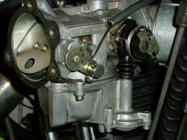
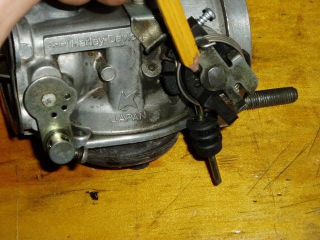
Accelerator Pump
The accelerator pump is the gizmo at the right in the first pic below. There is a diaphragm at the bottom, where that bulge is.
The pump pushrod sticks up inside that rubber bellow and you can just see it disappearing behind the black plastic knob.
The bent end of the accel pump rod engages in a small curved slot in the black plastic knob.
The accelerator pump adjusting screw is missing in the second pic below. Once removed, it gives full pump stroke all the time.
The adjusting screw should be through a hole in the top of that black plastic knob and limits the amount the black plastic knob can turn before it hits a stop.
More rotation equals more gas pumped, equals better pick up but lower gas mileage in traffic.
The choke on the '77 is the butterfly and linkage at the left in the second pic. The cable is disconnected for service.
79 and later have various different linkages here for high idle speed when the choke is used and various others.
Accelerator Pump Rod Length
Another important modification to aid smooth idle, according to Minton' s article, is to file the end off the accelerator pump rod.
This stops it resting on the pump diaphragm at idle and jiggling it up and down, pumping minute amounts of fuel into the carb throat.
(which dribbles along the bottom of the throat and is not properly mixed with air so it makes the bike run rough}
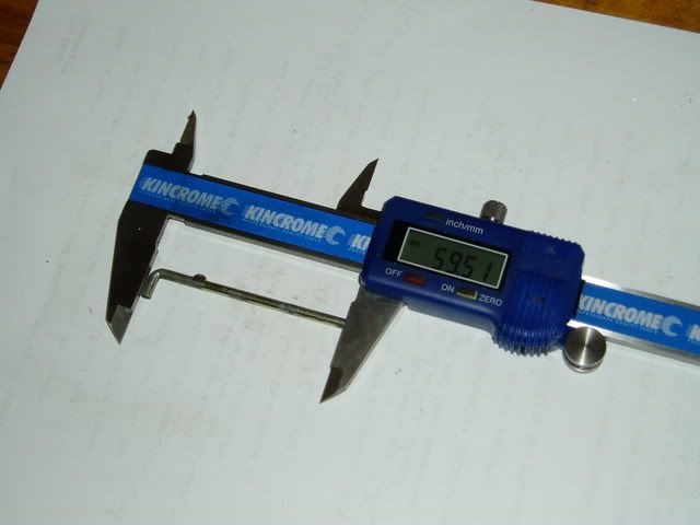
The factory parts book specifies the standard length as 59.mm for the rod.
It's hard to measure because the end is not square.
But it still sticks out beyond the carb body at idle and pushing on the diaphragm.
The carb 'trouble shooting chart' in the manual lists “accelerator pump pushrod incorrectly adjusted” as one cause of rough idle.
But does not offer any information on how to adjust it.
You can file about .010”-.015 inches off the straight end of the pump rod if sticks out past the end of the hole it sits in at idle.
Then when assembling the pump, check that you can grab the pump rod with a pair of long nose pliers and feel that it has some up and down shake when in the idle position.
You'd think this might cause a slight delay when cranking the throttle from idle, while the slack is taken up.
But it has been done and on the road, it was detectable for any delay. The gap is so tiny.
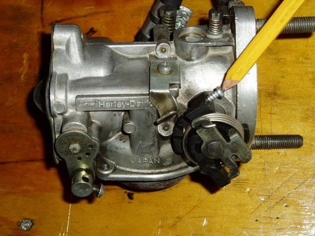
In the second pic below where the right-angle end of the accelerator pump pushrod fits, the bottom straight end is the end to file down very slightly.
This accelerator pump adjusting screw adjusts how much gas is pumped out by the accelerator pump.
(each time you crank the throttle in the first 1/4 to 1/2 of throttle opening)
Some have ran for years with no screw in here, which works fine and gives maximum fuel every time you crank it.
However, if you put one in and set it to the factory 1/4“ gap, maybe it will save a little gas.
Note: If you have a 79 or later carb, the front side will look a little different from the one below.
(due to the fast idle linkage between the choke and the throttle butterfly someplace here)
Note:
If the accelerator pump rod is too long, it will be spurting fuel at steady throttle. 34) 35)
You only need to shorten the accelerator pump rod, if while running, it is spitting fuel out of the pump jet (into the venturi at steady throttle).
If it is spitting, you will be able to see it doing so. This was a fix from the factory.
Do not shorten it under any other circumstances.
Check the pump nozzle aim
On 79 and later 34mm Keihin butterfly carbs,
Do not re-aim the accelerator pump as recommended in the magazine article. 39)
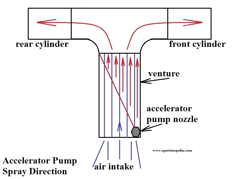
The spray does not atomize as it passes thru the venturi, so that if it is aimed too far to the rear or front that cylinder will get all of the fuel.
If you re-aim the jet so that the stream is aimed at the middle of the manifold, then virtually all of the fuel will go to the front cylinder.
Also, the front cylinder spark plug gets very dark brown, almost black, while the rear cylinder plug is a nice light tan.
This is under riding conditions where the accelerator pump is used a lot, like in-city riding with lots of short bursts of acceleration.
In the diagram below, the black represents the venturi, the red represents the stream of fuel from the accelerator pump jet, and the blue represents the air stream.
As long as the jet is aimed directly at the rear cylinder roughly equal amounts of fuel will be directed to each cylinder by the force of the air stream.
So, if you are running a Keihin butterfly carb, the fuel should go thru the middle of the cutout in the choke plate with the choke fully open.
 40)
40)
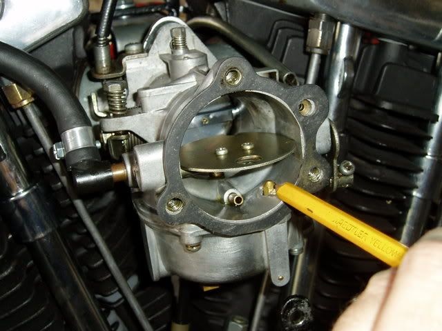
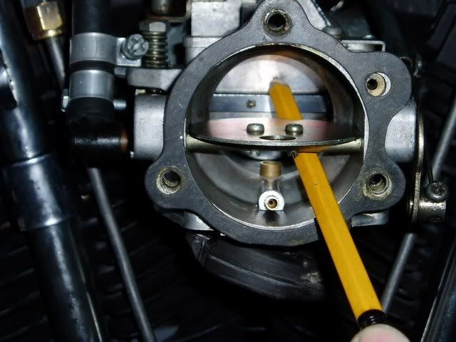
On 76-78 38mm Keihin's, the nozzle needs to be aimed so the squirt goes through the little cutout in the choke butterfly disc and does not hit the choke disc and splatter.
The jet of gas can hit the choke butterfly in the open position, so big blobs of unmixed fuel can get sucked in.
It may not fire down the manifold throat as some have observed, because the throttle is not far enough open to allow that.
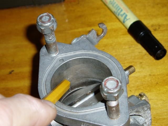
There is a small notch in the choke butterfly.
The accelerator pump jet needs to be rotated so the squirt of fuel goes exactly through that notch (when choke is open) and hits the throttle butterfly dead center just above the two spindle screws.
The nozzle is a press fit into the bowl and may be tight after being there so many years.
See the point in the third pic below where the squirt of gas should end up.
(from the pump jet, through the tiny notch in the open choke and into the center of the throttle butterfly)
Due to limited space, you can use a 5mm short socket turned with pliers or a box end wrench to turn the nozzle.
Do not use pliers or an open end wrench on the jet itself.
The tool has to contact all six sides of the base of the jet (otherwise, because it is in there so tight, you risk wrecking it)
Caution:
It is possible to break the nozzle when trying to remove it. Replacements from J&P etc. may still be available.
As a precaution, you can heat the float bowl gently and evenly. 41)
The aluminum will expand more than the brass nozzle, so the fit will become loose and make it easier to turn the nozzle.
You can heat it with a heat gun, a good hairdryer or even drop the float bowl in a pot of boiling water for a few minutes to heat it up.
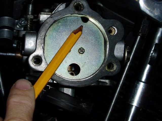
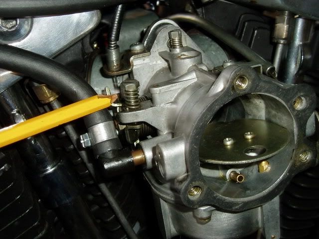
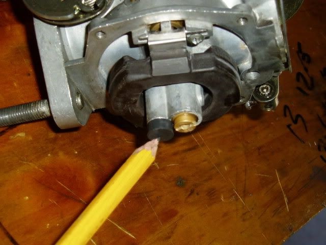
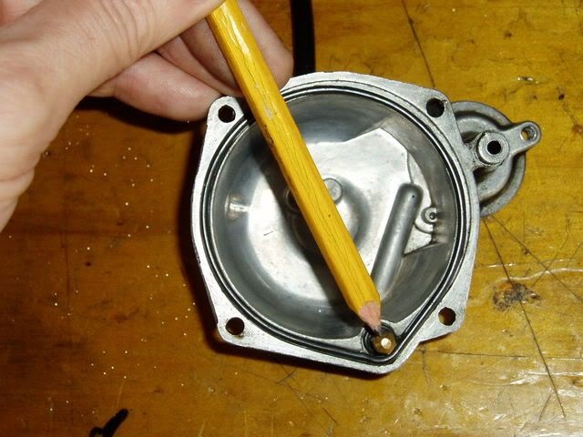
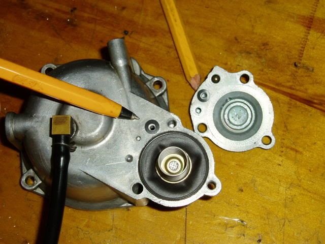
The jet below was aimed too far to the left hitting the choke butterfly and heading toward the back cylinder in unmixed blobs of fuel.
The pencil shows the direction the jet hole was facing before adjustment.
| Before adjusting. 44) |
 |
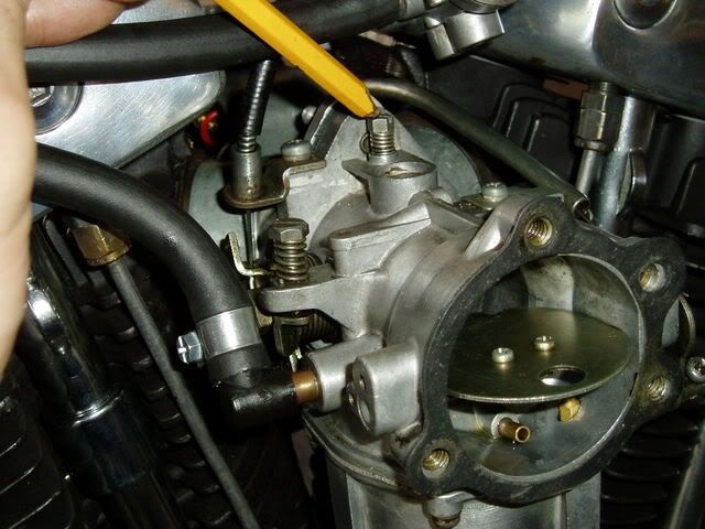
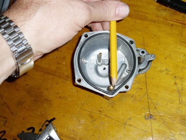
The jet position was then adjusted with a small crescent wrench to rotate it to the right. The pencil below shows the new direction of the hole in the jet.
This lined the gas stream up with the notch in the choke butterfly perfectly when reasssembled.
Note: The pencil point is to the right of the jet hole. The spray direction is in line with the lefthand edge of the pencil.
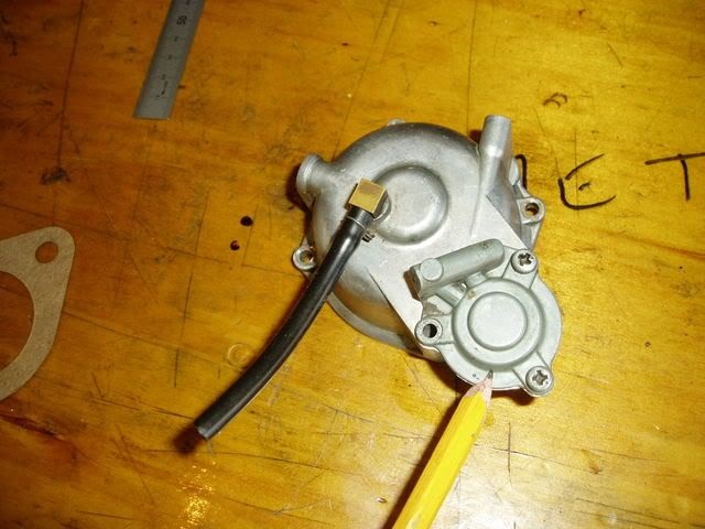
The black tube in the second pic below on the float bowl is the overflow tube.
Caution:
Make sure you plumb a line to this that goes past your bottom frame rail to dump gas and fumes.
Any wiring that that may get too hot / catch fire doesn't need gas nearby.
While installing the accelerator pump, the diaphragm goes on first, then spring, then cover.
Make sure those two square section O-rings are in place and in good condition. Else, gas will leak out there instead of getting squirted into your engine.
Float Level Adjustment.
The float needle should just kiss the seat with no extra pressure.
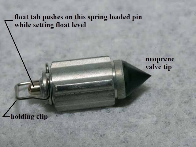
Aftermarket float valves have a spring loaded pin under the float tab.
So when the valve tip closes onto the seat, you can still push the valve down further.
The valve should 'just' close when measuring the float level. Pushing further in from there will not close the valve any further.
But it will cause you to set the float level wrong. The valve should be a light seat when measuring.
Some aftermarket float needles with the spring loaded pin also have a defective neoprene tip on the other end, which does not seal even when set right. 48)
Since the tip on the needle on aftermarket ones don't work well, some would use the old original one (solid pin) to get a better measurement. 49)
Beats assembling the carb only to have it sit there and flood with gas.
Also make sure you have the float valve for the correct type of Keihin carb. The CV valves are a little taller.
 50)
50)  51)
51)
The measurement in the FSM is a reference point that will keep the OEM float within a fully open and fully closed position.
Using aftermarket parts, you may have to adjust some.
With carb in bike, you can put a small catch tin under it and turn on the gas and move the float until the flow of gas actually stops.
(with no smoking or flames of course)
You make the adjustment by bending the little tab that pushes on the end of the float needle.
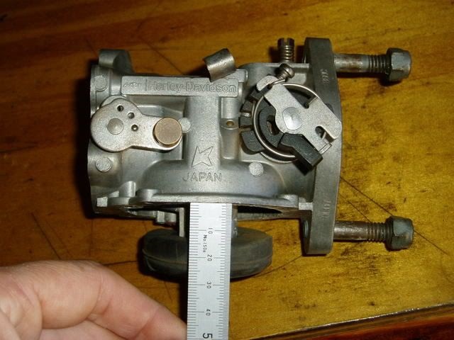
The -78 FSM specifies this distance as 9/16” to 5/8“ (14mm-16mm). Setting the float lower will tend to make the carb act lean at low speed.
Setting the float high can cause rich running, flooding and dribbles out the overflow line.
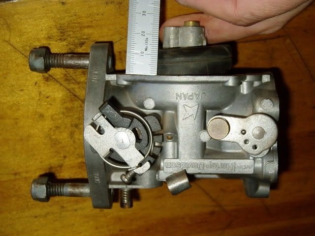
Equally important is to set the wide open float setting by bending the other metal tag on the float by the pivot. It should be 28mm-30mm.
This makes sure the float needle fully opens at full throttle openings and allows full fuel flow without starvation.
It also stops the float hitting the bottom of the float bowl and possibly getting damaged.
| Setting the float level. 52) | |
 |  |
Keihin Butterfly - Rebuilding / Refreshing
Disassembly
- Removing the carb from the bike should be straight forward. First thing when it is out is to check the pilot screw setting. 53)
Turn it all the way in until gently seated counting the number of 1/4 turns; then write this number down; then reset it.
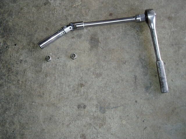
This rig works well to get the carb off to fit the heat block without having to take off the horn and ignition switch brackets.
1/2” deep socket, 3/8“ drive, universal joint and 6” extension.
 54)
54)
- Pilot screw:
- Remove the pilot screw and clean the parts and the passage.
- The passage contains in this sequence: (pilot screw, spring, washer, O-ring).
- These are very small parts, especially the washer and O-ring. Usually the spring will easily fall out.
- The technique for removing the washer and O-ring is usually to use a pipe cleaner:
Stick it in the hole, twist it around, remove it - you should see the washer and O-ring on the end of the pipe cleaner.
Remember that the purpose of the washer is to protect the O-ring from the spring and you will always get them back in in the correct sequence. - Note: Some carbs, notably 1966 to 1978 Sportster carbs, do not have the O-ring and washer in the pilot screw passage.
- Float:
- Handle the float carefully so as to not change the level.
- Jets:
- The jets are made of brass, a soft metal that is easily damaged.
Use an exact correct size screwdriver to keep from damaging the slot.
You can grind a medium flat blade screwdriver down to exact size on a bench grinder to access the slow jet. - Make a list of all of the jets and passages for your carb using the carb manual or the FM for the bike.
Then ensure that you can blow either compressed air or carb cleaner thru each one.
- Accelerator pump:
- Dismantle the accelerator pump assembly noting carefully the sequence and orientation of the parts.
- Clean and inspect the parts.
- Replace the diaphragm if it is cracked.
Cleaning
- The general appearance of the inside of the carb is not necessarily a good indication of its condition.
It can look spotless and have clogged jets, or look cruddy and have clear jets. - It's good to clean each individual part rather than soak or boil the whole carb in carb cleaner.
But either way is good. Do not allow any solvents to contact any rubber parts (tip of needle, O-ring seal for bowl). - Make sure to take everything apart, jets, needle, accel pump, all rubber components especially.
- Examine all parts for excessive wear, damage, distortion, etc.
- Cleaning solutions/sprays vary based upon your location, needs, budget, preferences and quality.
Dismantle the carb down to the body before soaking. You will be surprised at all the dirt in the bottom of the soaking container.
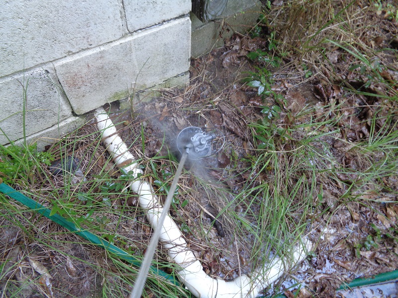
Here are some helpful ideas:- An overnight soak in a solution of Pinesol and water followed up with a good brush down with a toothbrush then rinse and air dry. 55)
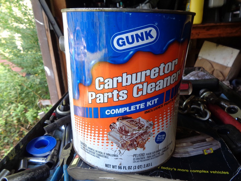
- A 20 minute to up to a few days soak in a gallon of Gunk (or other) Carburetor Cleaner that has a basket inside for small parts and lowers in the can with a handle, rinse, air dry, use.
- Soak it in mineral spirits for a few days. 56)
- You can use acrylic paint thinners for cleaning up carb parts. It melts the fuel varnish right off. 57)
- An aerosol spray carb cleaner will also work but may not loosen all of the build up in the jets or orifices in the carb body if they're not directly sprayed through.
- Blow out all holes, jets and orifices thoroughly with compressed air after cleaning.
A gallon of carburetor cleaner is very useful in cleaning parts.
It is especially useful for soaking stuck gaskets between parts and loosen the joint between them for dis-assembly.
Depending on how old or how 'stuck' the parts are, soaking for a couple hours may help to separate the old gasket in between.
Make sure to remove any rubber or plastic parts before soaking. Also check the label for safety precautions.
Parts that have been sitting for years may have to be soaked for about 24 hours or even days.
| Carburetor Cleaner 58) | |
 |  |
Carb Stand:
- You can put the carb in a vice to remove the screws, and for much of the following work.
Wrap in a shop towel; close the vice gently taking extra care with the choke and throttle linkages.
The vice is a needed extra pair of hands. - It can be very confusing trying to decide which way to bend the tang if it is not correct.
If the fuel level is low,Is the float high or low?, Do you need to bend the tang up or down? etc.
On the bench the carb is usually upside down, adding to the confusion. You should sort all this out before making an adjustments.
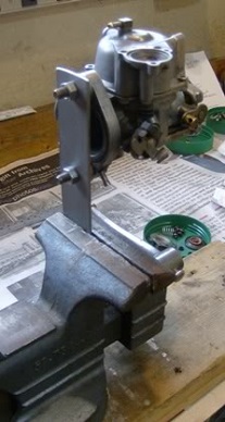
However, this setup works better than putting the carb (pre-CV) directly into the vice.
The carb is set upright as 'in use' making adjustments more straight forward.
 59)
59)  60)
60)
Servicing the Carb
See also Keihin Carb Upgrades - Butterfly and CV Types in the REF section of the Sportsterpedia.
You can purchase individual parts or a rebuild kit. The kits will not have needles, jets or the spring, washer & o-ring for the Idle Mixture Screw.
The rebuild kits are usually less than $20 and include:
- Carb-to-Manifold Seal
- Carb-to-Air Cleaner Gasket
- Float Bowl Gasket/O-ring
- New Float Needle
- New Accelerator Pump Diaphragm & Spring
- Some Misc Parts/Seals
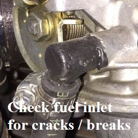
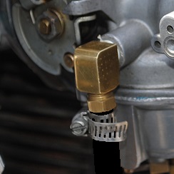
Check the plastic fuel inlet for cracks or breaks. Time will make the plastic brittle. You can be proactive and just replace it with a brass 90 elbow.
See Replacing the Plastic Fuel Inlet Fitting with a Brass 90 Degree Fitting in the Keihin carb upgrade article in the REF section of the Sportsterpedia.
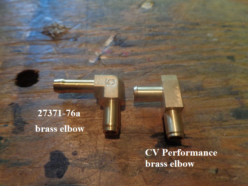
The brass replacement elbow part number (27371-76a).
The CVP brass elbow fits Harley CV40 carburetors 1988-2006 and Harley Keihin “butterfly” carburetors 1981-1989. 61)
Helpful Video Links:
Here are some excellent videos of servicing the pre-CV Keihin Butterfly carbs:62)
Flange Repair:
For a broken flange, you can try milling some slots in the flange and drill and tap the holes for screws.
You can use some JB Weld in there to insure a good seal.

Assembly
- Check float level:
- Use the specs in the FSM for setting the float level and check it every time you dismantle the carb (as the last thing before putting it back together).
- After checking the float level, then carefully put it back together.
- Replace the screws:
- It's best to replace the original Phillips screws for the bowl with stainless steel socket head screws.
Add'l Info & Pics -
Accelerator Nozzle, Check Valve, Float Seat - http://xlforum.net/forums/showthread.php?t=1624208
Accelerator Nozzle & Check Valve - http://xlforum.net/forums/showthread.php?t=1775068
Troubleshooting
- The Phenolic fiber spacer helps with hot idle or starting problems:
- One infuriatingly simple thing that affects idle, starting and carb farts when your engine is hot, is this phenolic fiber spacer.
It's between the carb and manifold, which some models had and others did not. It stops engine heat from flowing into the carb.
If your model doesn't have one of these stock, you can cut one out of a sheet of fiber about 3/16“ thick.
JP Cycles or others sell one that is a bit thicker and might work even better.
The one below was fitted as shown in the pic below and the parts book.
There should be a gasket on each side of the spacer while still using the rubber O-ring on the carb flange.
Of course, make sure both the carb flange and the manifold are filed nice and flat with a 10-inch flat file first.
Without it, your carb can get too hot to touch within minutes of the bike being parked with a hot engine.
Even the air filter gets hot.
There is a lot of heat flowing from the heads, up the manifold and into the carb which makes it hard to start and idle rough.
The heat vaporizes the fuel in the float bowl and it can boil and come out the overflow tube at the bottom of the float bowl.
This also means the tiny amount of fuel trying to go through the idle adjuster screw and into the carb throat can also vaporize.
Fuel going into the engine needs to be tiny globules of liquid fuel, not vapor.
Putting a heat-blocking spacer on is really worth the effort if you ride a lot in city traffic.
(where idling at the lights will allow heat to flow into the carb while there is no cooling wind)
With a kicker only XLCH, the easier hot starting is a Godsend.
- Pilot screw:
- The pilot screw adjustment mainly affects the idle speed operation of the engine. 66)
This is when the engine is actually idling, and when you release the throttle while riding.
If the pilot screw is too lean you get backfire in the exhaust when you throttle down, and white looking spark plugs.
If it is too rich you get black sooty exhaust and black sooty spark plugs.
Either situation has serious consequences for engine longevity if left unresolved. - The mixture screw does not have a large range of adjustment, if you're running lean, you may need to increase the low speed jet size.
(after you have eliminated all other contributing factors)
- Fast idle:
- A fast idle can be caused by the idle not being set when the bike is HOT. 67)
- A fast idle can also be caused by an advance mechanism that is not functioning correctly.
- Spitting / Backfire thru the carb:
This is most certainly a tune-up problem. 68)
The main causes of carb farts are lean mixture, retarded spark and tight pushrod clearances.- Lean condition:
- Lean mixture can be too small jets, too low float level, leaking intake manifold, gunk in the carb. 69)
- As an intake leak test, you can use WD-40 or propane gas.
There is no technical need to be concerned about some explosion, and it is the best and cleanest choice.- You have to spray a lot of WD-40
(from both sides of the engine, around the joints, between the head and the manifold and between the manifold and the carb).
WD-40 leaves a mess. For a test, spray some into the air cleaner. The idle speed will go down, perhaps stall the engine, right away. 72)
If there is a leak you will get a slow down of the idle speed. - The propane is nice and neat, and has finer particles so it should find smaller leaks.
- For coughing and spitting, you can try drilling out the low speed jet to 1/32” (.031“) . 73)
- The coughing and spitting is a combination of things but this may cure it.
You can buy the biggest low speed jet available, hear the carb cough from it and then return back to the smaller one (or smaller size).
- Another thing to look at is to be sure your air cleaner is free flowing. In other words, make sure it's getting plenty of air.
If you are running the 72 air cleaner backing plate, the outside of it should fit to the size of the air cleaner.
The 77 and later backing plates had an air horn and they weren't getting enough air. - Backfiring can be caused by bad plugs.
Use standard OEM style plugs and buy a box of them until you get it sorted out.
If you have electronic ignition, you must use resistor plugs.
Start with a small gap, .025 and increase gap as you are able, electronic can go as high as .045. - Retarded spark:
- Retarded spark is usually from a worn out auto advance unit in the ignition allowing too much retard at idle.
- Running the ignition timing slightly advanced is good. 74)
With points, we used to run them advanced up to 8-10 degrees so that when the points wore, they would still be in an acceptable running time.
With electronic ignition, the timing never changes so 2-4 degrees advanced is about right.
Time it with a light and run the motor up to full advance (about 2500 RPM).
- Pushrod adjustment:
- Pushrod adjustment can also cause it and is easy to check.
- Air / exhaust gas blowing out the carb:
- Air blowing out the carb is a timing issue. An intake valve may be open when it should be closed. 75)
You'll need to pull the gearcase (cam) cover and check the timing marks on the cams.
If you have not had this cover off before, be sure to remove the pushrods first. - Running hot:
- Running hot can be caused by vacuum leaks or bad ignition events.