Table of Contents
This is an old revision of the document!

IH: Engine Mechanicals
Installation of Top End
- Put the rocker boxes on the heads at 18ft-lbs / 200 in-lbs. 1)
- With the cylinders still loose at the base nuts, drop the heads on and run the head bolts in until contact, then loosen 1/4 turn. 2)
- Get your intake manifold and align the heads (rotate cylinders and heads to get ports to align to manifold) 3)
- If, when all is assembled, you cant wiggle the carb/manifold/ac in relation to the motor (solid mounted) then you've got problems. If you go to split clamps also then your as good as you can get with rubber-band seals. 4)
- The O-ring set up is subject to the same principals. Its more robust in mechanical design than the band, so it's even more reliable. But, it's more misunderstood in the way it goes together, so it gets a bad rap. If you have O-ring heads, not using the O-ring is just shorting yourself. 5)
- If not, going to the O-ring will be more attractive. 6)
- The advantage of the O-ring is that the clamp can be used to help make a solid connection between the manifold & the heads (no rubber in between). This totally removes the rubber / metal interface of clamp /rubber-band / spigot (the core of the degradation you are trying rid yourself of). The reason most O-ring setups fail is the commonly held idea that the closer the manifold and head get to 'no gap fit' the better the O-ring will seal which is totally wrong and the cause of 99% of O-ring sealing issues. When the manifold is set tight against the head, there is a groove created that the O-ring lives in. Common belief is the O-ring seals in this groove. It doesn't. In fact, this makes the groove smaller in volume than the O-ring volume. So, when the clamp compresses the O-ring on its way to getting tight to spigots, the O-ring fills the groove and forces the manifold away from the head in order get enough volume to fit into. Now nothing aligns right and it leaks right from the start. 7)
- The right action is leaving a gap of .030“ - .060” (1/32“-1/16”) between the head and manifold at the skinny lip. This gap needs to be even all around on both heads at the same time. It's in this little gap that the O-ring seals when the clamp squeezes it. When setting the heads & jugs for alignment and installing the manifold & O-rings with no clamps in place, the inside of the manifold should match the inside of the intake port all by itself with no forcing. Don't worry if the gap seems too big. It will shrink when the heads & jugs get tightened. The last test is when clamps get tightened, that the alignment is still on. Before you tighten the clamps, you will note that the O-rings are proud of spigot diameters. When the clamps squeeze the O-rings to the spigot dia., the seal to gap occurs. During the tightening, you may have to tap the manifold back into alignment until the clamps grab onto the spigots. 8)
- One thing to remember when using O-rings is that they should be conditioned before use using a dielectric grease. You could also just wet the O-ring with oil or grease. What this does is it softens up and swells the O-ring so you get better sealing. 9)
- Snug the cam side center (of vee) base nuts. 10)
- Re-check alignment. 11)
- Snug cam side center head bolts. 12)
- Re-check 13)
- Tighten base nuts. Don't go ape on torque. Iron heads use fine threads, cars use coarse. Fine threads have way more mechanical advantage. 14)
- Tighten all head bolts somewhat. 15)
- Re-check. 16)
- Get a nice 3/8“ breaker bar with a nice 9/16” socket and tighten all 8 head bolts to the same feel. 17)
- Now switch to torque wrench and check all 4 primary side bolts (a beam or dial wrench is a bit less tedious). 18)
- You will find your 'feel' is pretty damned consistent. 19)
- All that's left is to get the feel for 60-70 ft-lbs. 20)
- Just creep up to it. 21)
- Usually you will find that right in the 60-70 range is when the bolts attain the 'socked down hard' feel. 22)
__
Head Identification
4 steps to head identification just from site plus head bolt spacing: 23)
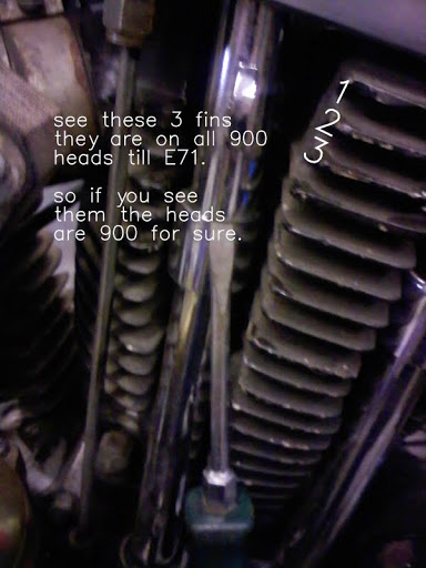
| 1a. If these fins are present, your looking at 900 heads for sure. In later 71 these fins disappeared. That means:24) | 1b. There are some 900 heads that didnt have those fins and no 1000 heads have these fins. If no fins go to step 2.25) | 2a. Decide if the heads are later 71 (900) or 1000. Do that by looking at oil drain size Note the size of drain compared to head bolt holes.26) |
 1957-71 bolt pattern ( inside of hole to inside of hole, diagonally ) is 3.440“. 57-mid 73,threads for head bolts, come all the way up to the head gasket surface on the cylinders.27) | 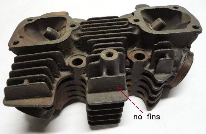 | 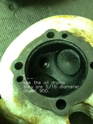 |
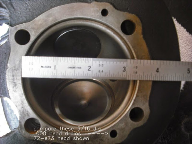
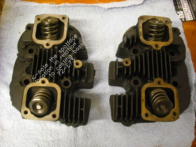
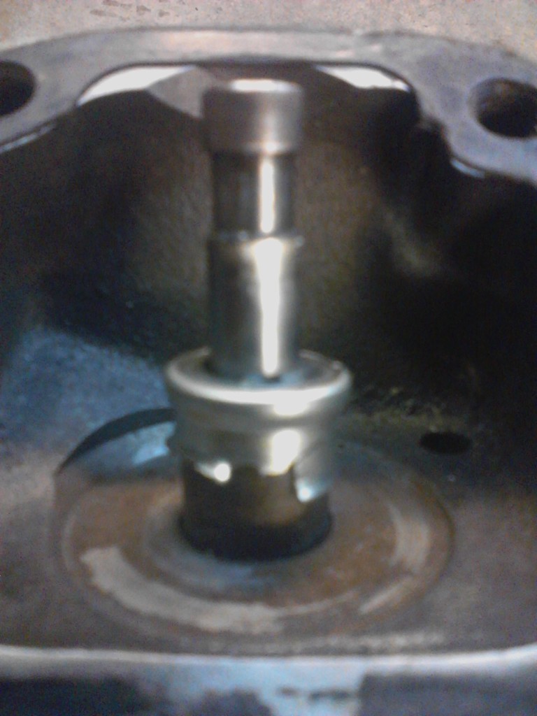
| 2b. 1000 uses 3/16” oil drains. Now you know if your looking at late 1971 900 (big drains) or 1000 (small drains). If heads have small drains go to step 3 to determine if heads are E1000 (72-E73) or L1000 (L73-78). 28) When the change to 1000 happened in 72 the cylinders casting size was increased but for augments sake the head casting was not. Consider the cylinders: The bore was opened .094“ radius. That pushed to the oil holes in cylinder to a larger pattern. To get the matching larger pattern in the old heads, the holes needed to be reduced in size so they still fit in the 900 size casting.29) | 3a. E1000 (72-E73) On 900 heads (smallest bolt circle), the bolt holes bulls-eye the casting boss. Looking close at the 72 heads you can see the bolt circle was slightly enlarged while the casting boss stayed at the original position. 30) | 3b. L1000 (L73-78). In later 73 the 1000 heads change to bigger bolt pattern.31) The L73+ heads have the spot facing further out on the casting boss. In other words, the PCD of the spot facing is greater than on the 72/e73 heads. 32) In L73 the bolt circle was really enlarged. Again the boss stayed at the 900 position. There is added meat around the bolt holes between the fins but that's a moot point in identifying what year heads your gawking at. 33) |
 |  72-mid 73 1000 bolt pattern ( inside of hole to inside of hole, diagonally ) is 3.540”.34) | 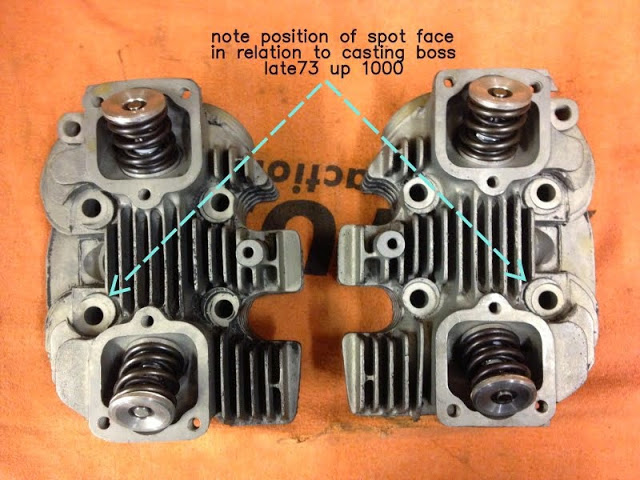 L73 - 85 bolt pattern ( inside of hole to inside of hole, diagonally ) is 3.640“. Late 73-85 threads for head bolts are recessed in the cylinders by 1/2''35) |
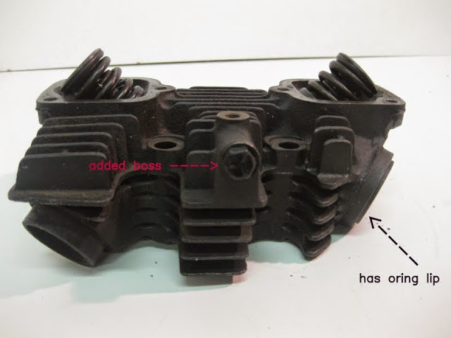
| 4. In 79 a boss was added for a/c mounting. This is a 79 only head. 1980-1983 is same as 1979 but doesn't have the intake o-ring lip. 84-85 had no intake o-ring lip either. The air cleaner boss was still present but it wasn't drilled or tapped.36) | 84-85 heads also had the shoulder-less valve guides and took a small washer for the inner valve spring instead of the full size lower spring collar the previous heads used. The valve guides do require machining if you want to use a seal the top spring collar will contact them. 37) While this info is accurate, don't let missing guides or incorrect vintage guide installation influence you in identifying what heads you are looking at. 38) | |
 |  |
Other Pics of Iron Heads
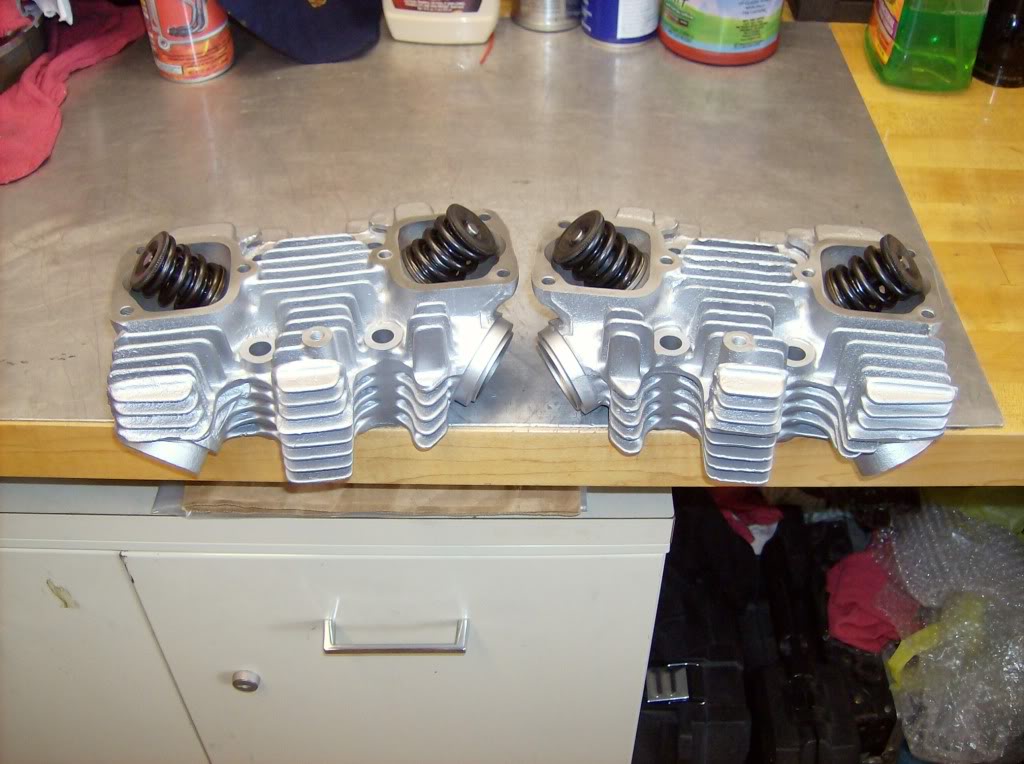 |
| 1969 Iron Heads 39) |
4)
, 5)
, 6)
, 7)
, 8)
(Dr Dick of the XLFORUM http://xlforum.net/vbportal/forums/showpost.php?p=3203642&postcount=30
23)
, 24)
, 25)
, 26)
, 28)
, 30)
, 31)
, 36)
Dr Dick of the XLFORUM http://xlforum.net/vbportal/forums/showthread.php?p=5133944
27)
, 34)
, 35)
brucstoudt of the XLFORUM http://xlforum.net/vbportal/forums/showthread.php?p=4022291
29)
Dr Dick of the XLFORUM http://xlforum.net/vbportal/forums/showthread.php?t=1876615&page=2
32)
Scuba10jdl
33)
DR Dick
37)
mct496 of the XLFORUM http://xlforum.net/vbportal/forums/showthread.php?p=5133944
38)
Dr Dick
39)
photo by Monte03 of the XLFORUM http://xlforum.net/vbportal/forums/showthread.php?t=166440&page=6