This is an old revision of the document!

IH: Wheels, Brakes & Tires - Sub-01A
Problems Associated with Drum Brake Rear Hubs
Article by Dr Dick of the XLFORUM 1)
- The problems associated with drum brake rear hubs depends on your definition of what a problem is to you. If you have reoccurring problems with wheel bearing failure, brake performance or chain life, this info maybe helpful in tracking down the cause.
- In getting familiar with hub the differences over the production years.
- Common to all hubs:
- All models used the same single row bearing on left side.
- All bearings referred to below are the right side.
1952-1954 ↓ models:
- Used the asymmetric flange hub (smaller spoke flange on left side).
- Torrington needle bearing (9011).
- Used the grease shield assembly between right bearing and brake backing plate.
- This shield is same design as the swingarm Timken shields.
1955-E1958 ↓ models:
- Used the 1st symmetric flange hub.
- No bearing change.
- Used the grease shield assembly between right bearing and brake backing plate.
L1958-1962 ↓ models:
- Same hub as previously used.
- U the double row 'duplex' ball bearing (9010).
- This is basically two bearings in one.
- Used the grease shield assembly between right bearing and brake backing plate.
1963-1965 ↓ models:
- Same hub as previous.
- Used two separate single bearings (9008) & (9009) stacked up.
- Grease shield is no longer used.
1966-1972 ↓ models:
- The brake side hub flange was made thicker at the bolt mounting area.
- Longer drum lugs were used.
- No bearing change.
1973-1978 ↓ models:
- Some time between 1973 & 1975, brazing got replaced by welded construction.
- No bearing change.
In summary, there were 3 hubs and 3 different right side bearings setups from 1952-1978.
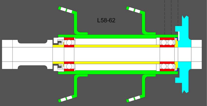
| This is the L1958-1962 setup: 2) |
 |
| This is two pics in one. The 63-65 is the top half and the 66-78 is the bottom: 3) |
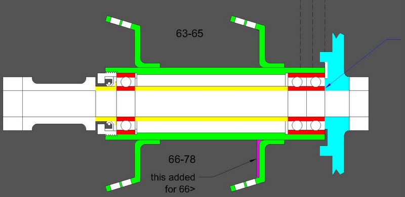 |
- In the above pics, you see everything that assembles in between the swingarm legs, (i.e. the chain adjusters, backing plate, and axle spool spacer). The dashed lines represent the chain position.
- What you don't see is the tin spool that covers the inner bearing spacer which was left out because it's not part of the structure and it's job is to take up space so you don't have to fill the entire hub up with grease.
- Regarding bearing issues.
- The most common of all hub complaints is the outer right side bearing being loose in the hub. This is very common on '66→ hubs but not as common '63-'65 and non existent on → '62.
- This loose bearing is never a problem in itself. It won't leave you stranded.
- The reasons it happens are many from;
- The bearing bores are not machined on the same center line. They are not concentric from one side of hub to the other. This misalignment imposes movement between the bear OD and the hub bore. That works the bearing loose by stressing the hub material (this kind of sloppy machine work is 'par for the course' in many aspects of these hubs). Some hubs are better than others with this. Earlier hubs were better than later ones.
- Forces exerted on hub tube during acceleration. The hub consists of 3 pieces, (2) - spoke flanges and (1) - center tube. This is more complicated. The tube ends up flexing in such a way that the material surrounding the outer bearing is deformed.
- Go back to the 2nd pic. The added meat on the drive side flange was incorporated because the earlier hubs would crack thru the thinner flange near where the flange met the tube. The upgrade stopped the cracking but didn't reduce the forces that cracked the hubs.
- With this added rigidity, a new problem started showing up.
- A loosening outer drive side bearing fit. All this is connected to the force the drive chain exerts to the flange (this was finally 'addressed' around 76 by increasing the press fit on the right side bearing set). This 'fix' resulted in shortening the life of the left side bearing.
- On a disc brake bike the sprocket is flat or almost flat. Where it connects to the hub there is flange. Under that flange is a bearing. All this is very close to being directly in line with the chain pull. Not so for drum brake bikes. The flange is moved 1-1/2“ off the pull line and the sprockets are cantilevered.
- If you stood facing forward, over the rear axle of your bike looking down, you would visualize that as the chain pulls, it also wants to twist the flange (and drum / sprocket) counterclockwise. This twisting of the thin flange would crack it after enough flexing. A rear hub that separates into 2 pieces will put you on the pavement. HD did the right thing by adding the extra meat. Even if it meant (which it did) that this extra meat now transferred that twisting to the hub tube where it would work the outer bearing loose (reasonable tradeoff). A loose bearing beats a loose collarbone every time.
- When you jump on the throttle, the hub is being pulled forward by the drive chain in addition to the far right side of the hub getting tweaked farther forward by the counterclockwise flex and it ain't done yet. All this wants to spin the tire on the macadam. Friction here drives the entire bike forward by also driving the hub forward. Except for the weight of the rotating rear wheel assembly, the entire weight of the bike, with you on it, is getting pushed forward thru the fit of 3 little ball bearings in the hub.
- Like any other load carrying bearing assembly, the rear axle / hub assembly is alive. It moves around under load (a lot in our case). The assembly moves around from heat also but that's not much of a factor here. Early on in the development of ball bearings, it was discovered that if you affix two or more bearings rigidly to an assembly the bearings will likely fail. If you relaxed the fit so only one bearing in a set was rigidly attached to both the stationary (axle in our case) and the rotating (hub) members and let the others 'float', the life span of the assembly was increased exponentially. You can see this all over our bikes (both hubs, generator, trans door, magneto, crank shaft etc.)
- So, the light press fit required to allow the float on the right side did nothing to combat the bearing coming loose. But it did give for a long working assembly with no side effect other than a loose outer bearing.
- Then, around 76, the factory abandoned good engineering and tightened up the press fit for the right side bearing set (kissing the float good bye). And just as it was 100 years prior, the assembly as a whole didn't last as long as before. Now the left side single bearing got overloaded because the tight fit doubles on the right bullied it into submission.
- Earlier, I said the whole assembly flexes a lot. Transmitted thru the hub, the axle gets the forces too. As the axle flexes, the whole bad scene snowballs.
- Look at the 2nd pic again where the naked arrow is. That's where the aluminum back plate butts to the bearing inner race. That race will and does plow rite into the soft back plate when the axle flexes. That's not the best scene either.
- Now look at the 62< pic at the same area. Much better. Putting the L58-62 bearing, center spacer and shield into a sweat brazed 66-72 hub gives the best bolt together setup.