Table of Contents

REF: Oiling & Lubrication
Measuring Output Volume (flow rate) of a Gerotor Oil Pump
See also Measuring Feed Oil Volume (flow rate) of the -72 Gear Type Oil Pump in the Sportsterpedia.
Disregarding variations in internal leakage, a positive displacement pump will discharge a specific volume of fluid per revolution.
That is irrespective of discharge static and dynamic head pressures. 1)
But what is the flow rate in gallons per minute (GPM) for both the feed and return sides of the pump?
One way to find out is determine how much oil one full tooth cavity holds and then do the math for revolutions.
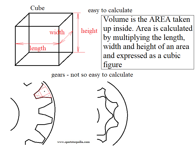
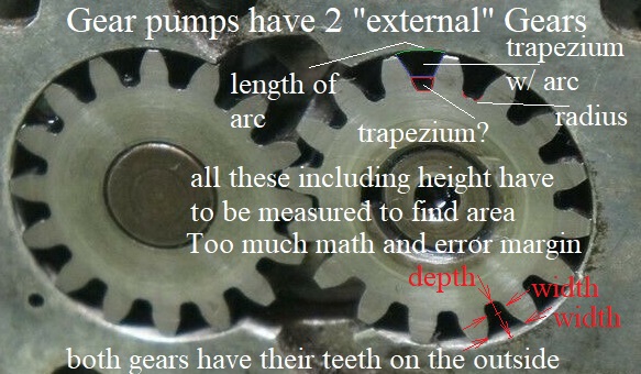
We can find the area of a square / rectangle / triangle box easily enough using line measurements and math.
But the gerotors in the oil pump are not straight lined and cornered.
The process below is the same as finding the volume of a combustion cylinder or head.
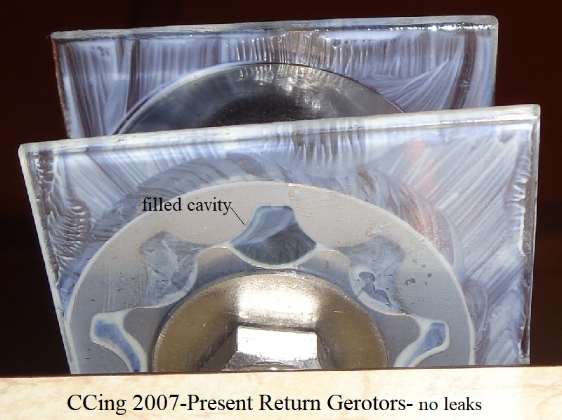
It's commonly known as CC'ing the chambers. Although in this instance, we are CC'ing one gerotor cavity and doing the math based on the results.
Measuring Volume of 1 Tooth Cavity
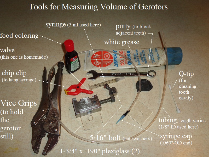
Equipment Used
✘ - Basically, a homemade burette was originally used in this testing but the error factor was too wide.
A burette is a graduated glass tube with a tap at one end, for delivering known volumes of a liquid, especially in titrations. 2)
It is a long, graduated glass tube, with a stopcock at it's lower end and a tapered capillary tube at the stopcock's outlet.
The flow of liquid from the tube to the burette tip is controlled by the stopcock valve.
The “burette” used here was a 3 ML syringe graduated in 10ths of a ML. The tube is 1/8“ medical air tubing with 3 internal runners up and down the tube.
The internal runners make it difficult to use since that stops you from making a tight seal if attaching the tube onto a nipple.
So the tubing used here was attached inside nipples to allow the tubing OD to create an air tight seal.
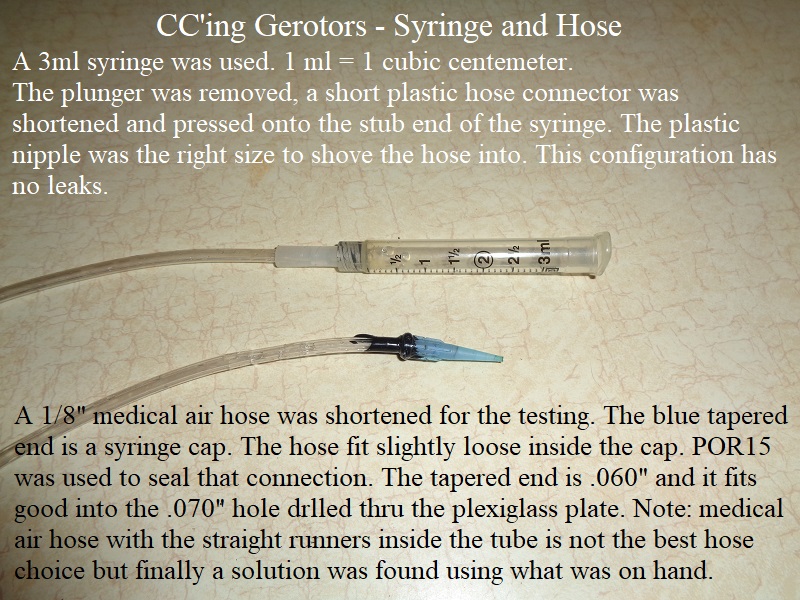
✔ - Testing with .5 ml SYRINGE USING THE INCLUDED PLUNGER TURNED OUT WITH TIGHTER RESULTS.
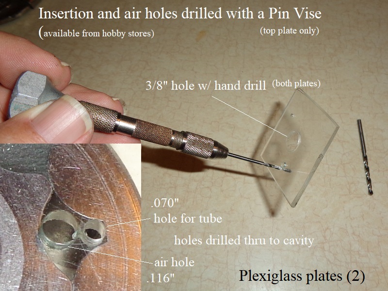
Two plexiglass plates were cut app 1-3/4 square with a Dremil cutting tool.
These didn't turn out the exact same size once filed and the edges sanded but as long as the are bigger than the gerotors, that's what matters.
A center hole was drilled thru both plates 3/8” with a drill motor and the edges file (drilling speed melts plexiglass and goops up around the hole).
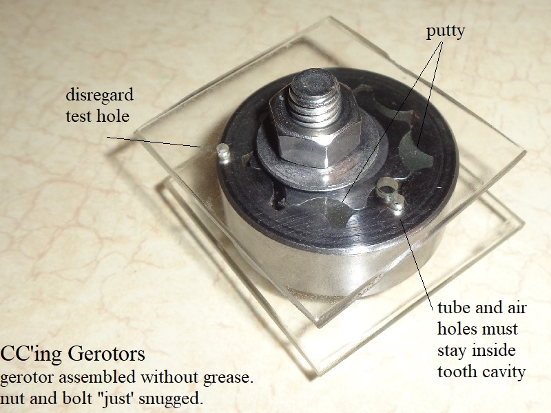
The center hole is for a 5/16“ bolt washers and nut to keep the plates snug against the gerotors (not to tighten against, just snug).
Tightening the center of the plates will make the ends of the plates flex outward and ruin the seal.
To keep from melting and gooping up the edges, the small holes were drilled with a “pin vise” (available at hobby stores) that doesn't melt the plexiglass.
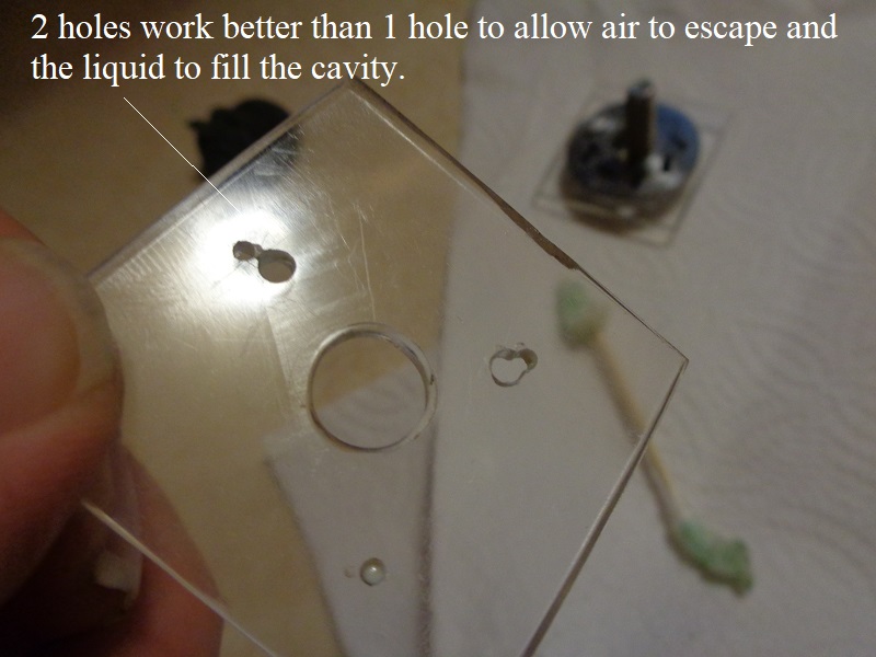
The small holes were drilled to fit inside the gerotor cavity (1 for tube insertion and 1 for air to escape).
The .070” hole fits the tip added to the end of the tubing. The air hole was drilled .116“.
 5)
5)  6)
6)
The valve was homemade from a scrap aluminum block.
A small hole was drilled thru the face of the aluminum for the tubing and a hole was cross dilled in the side to intercept the small hole.
3/8”x16 threads were then cut in the side for a tubing pincher.
A short piece of threaded rod was “balled” on one end to pinch the tubing.
The other end has a 3/8“ nut that was staked in place to turn the rod by hand. A 9/16” wrench is used to turn the rod into the tubing to pinch the tubing and throttle the liquid.
The white grease is to seal the plexiglass plates around the tooth cavity and keep the liquid from migrating across the faces.
The putty (electrical conduit putty from Lowes) is to block off adjacent cavities to keep the liquid in the cavity being tested.
A Q-tip is useful to clean the tooth cavity after pressing in the putty on each side (some may squeeze into the large cavity thru the clearance between the teeth).
The gerotors and plates need to be disassembled and cleaned before each test.
Margins of Error
The accuracy of these measurements requires precise measurement of the liquid. However, precision is not something you can completely control.
Some things you can control (human errors, construction errors)and some you can't control (liquid sticking to the syringe).
Errors at the syringe / tubing:
Syringe accuracy itself cannot be changed and has to be accepted as a “margin of error”.
Typically in a glass burette the uncertainty is ±0.15 cm^3 (0.15ml in a 25ml tube). 10)
The initial reading is said to be potential ‘out’ by ±0.05 cm^3 (liquid sticking to the sides)
The final reading is said to be potential ‘out’ by ±0.05cm^3 (liquid sticking to the sides from top of beginning to top of ending level)
And also there is said to potentially be a drop and the bottom of the burette, of a volume ±0.05cm^3 (liquid sticking to outside of the tip).
- Testing by others has shown a 4%-5% error margin when delivering liquid thru a syringe (using the plunger).
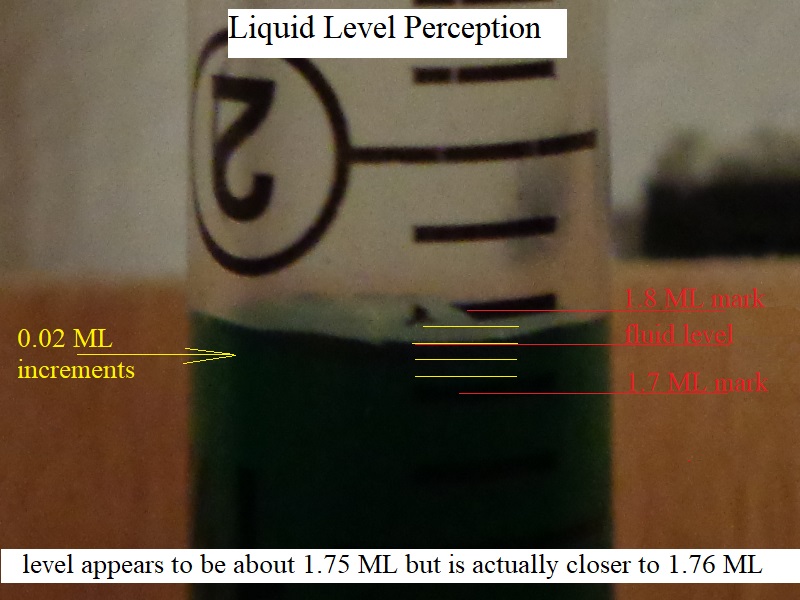
The plastic tube syringe has more wall friction than a glass tube also. - The markings on the syringe can be easily misread. One way to misread the volume is by looking at the measurement on an angle.11)
From above, it can seem like the volume is lower, while from below, the apparent volume looks higher. - Another source of measurement error is looking at the wrong spot.
When the liquid in the syringe forms a concave curve, the bottom of the curve is used to measure volume.
If the reading is taken from the higher sections of the curve, the volume measurement will be in error. - The graduations between the markings have to be guessed at (halfway between markings is easy to call a 1/2 of a mark but may be 1/3 of a mark).
Deciding between the 2.5 ML mark and the 2.55 ML mark on the 3ML syringe used here places you somewhere between 2.40 and 2.65 mL actual volume used (4% accuracy). - All air bubbles have to be removed or they will cause errors in the results. A small amount of displaced air will change the final reading.
The syringe used here was valved off with continuous water running thru it at the same time time to remove all air bubbles.
Then the green dye was added and the syringe topped off while running green liquid down to the tip.
Errors at the valve:
- The homemade valve used here isn't the best way to strangle water. But it does strangle water.
Having to use two hands instead of one and still keep eyeballs on the level in the gerotors is tedious. - A small valve made for a burette or lab testing is a better choice for smooth one handed operation.
Human error:
- Mathing is unforgiving and inaccurate results can be easily inputted due to individual perception of the level and markings.
- You have to trust your eyes looking for bubbles in the tooth cavity, fiddling with the valve, watching for leakage and at the same time watching the level.
- Mistakes are easy to make. Then the test has to start all over again and patience is key to good results.
If in doubt, disassemble, clean and retest. Repetition builds confidence. - Loading too much grease on the plates ends in squeezing grease into the test cavity and tainting the results.
Errors in construction:
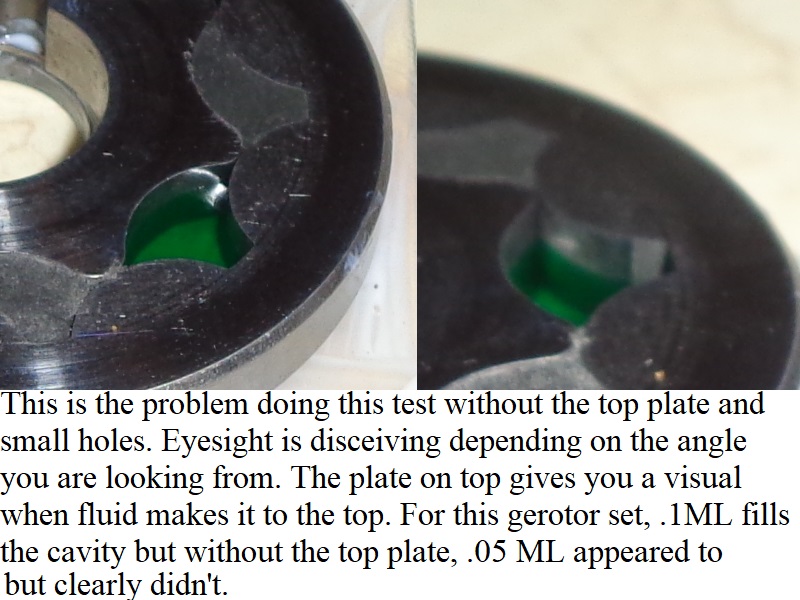
- The plexiglass plate on top is important as is the two holes to the cavity.
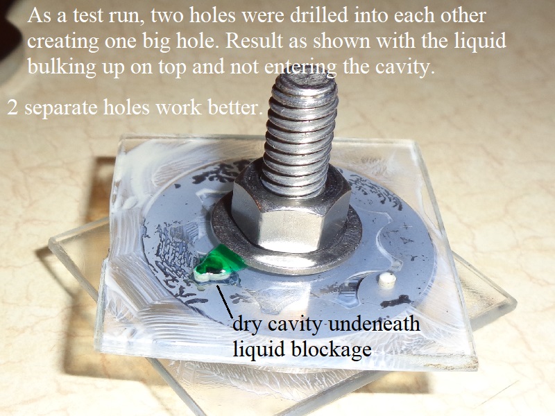
As a test, two more holes were drilled into each other to see if a bigger single hole might work better.
Result was the initial liquid drop sat on top of the big hole and blocked the cavity allowing it to remain dry while the gerotor face flooded.
The bulb of water coming out the end is the same size each bubble and are bigger than the holes in the plate.
So a big glop lands on the hole instead of in the hole.
The tapered end of the tube has to go into the small hole so the bulb lands inside the cavity.
So the 2 holes work better than a single big one. Pics shown below of that test but the single hole is not recommended in this instance. - Drilling holes in the plate, you have to make sure the edges are flush (no flashing left underneath to add plastic to the volume in the cavity.
The holes drilled here were carefully done and scrubbed to ensure straightness across the hole. - The inner and outer gerotors have to be the same height during the test or leakage will appear on top and bottom faces.
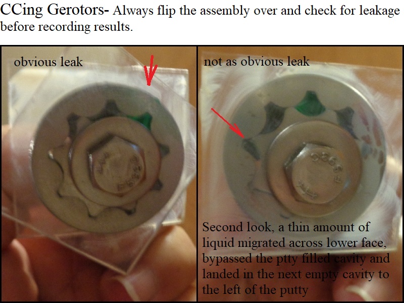
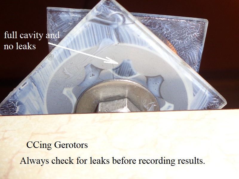
Leakage can also occur on the bottom but not the top.
So always check for leakage on both sides before recording results.
Error Factor Noticed Testing with the Homemade Burette
The 3 ML syringe is graduated in .1 ML increments (liquid between these marks has to be guessed or approximated)
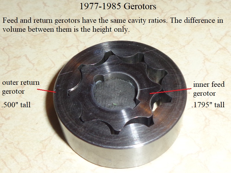
Return gerotor height is 2.785515320334262 times taller than feed gerotor height (0.5“ / .1795” = 2.785515320334262).
So the feed height (.1795“) x 2.785515320334262 = return height (.500”).
The gerotor pattern is exactly the same for feed and return gerotors.
You can fit the feed inner into the return outer with no space difference between the teeth.
The only difference is in the height of each.
Therefore, the volume of 1 feed tooth cavity x 2.785515320334262 should be equal to the volume of 1 return tooth cavity.
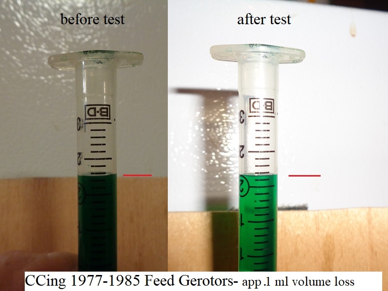
Doing the math, the testing didn't match those ratios very well.
Feed volume (.1 ML) x 2.785515320334262 = (0.2785515320334262 ML) but 1 return tooth volume was .3 ML.
A difference between overall volume and overall height of 0.0214484679665738 was present.
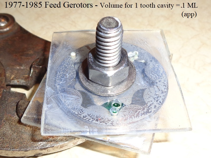
Feed Set
- Gerotor height = 0.1795“
- Gerotor volume = 0.104 GPM at engine speed of 1000 RPM (pump speed 500 rpm):
- One tooth cavity holds app 0.1 ml of volume or (0.1 cubic centimeters) or (.006 cubic inches).
0.1cm³ = .006 ci³ volume (0.1 / 16.387064). - Volume of eight tooth cavities per 1 pump revolution = 0.048 cubic inches (.006 ci³ x 8)
- Total pump volume at engine speed of 1000 RPM = 24 cubic inches per minute (.048 ci³ x 500 RPM pump speed)
- Feed pump volume = .104 gallons per minute at engine speed of 1000 RPM (24 ci³ per minute / 231)
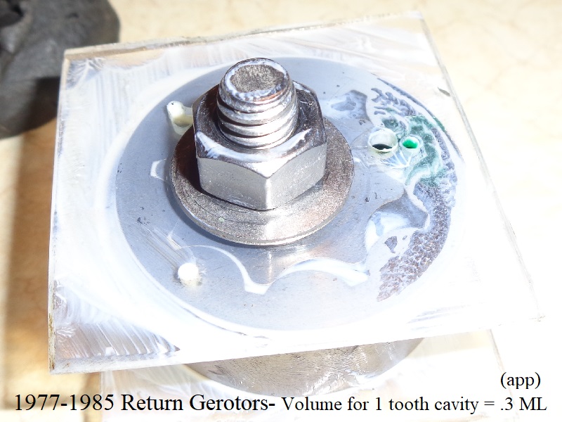
Return Set:
- Gerotor height = 0.500”
- Gerotor volume = .312 GPM at engine speed of 1000 RPM (pump speed 500 rpm):
- One tooth cavity holds app 0.3 ml of volume or (0.3 cubic centimeters) or (.018 cubic inches).
0.3cm³ = .018 ci³ volume (0.3 / 16.387064). - Volume of eight tooth cavities per 1 pump revolution = 0.144 cubic inches (.018 ci³ x 8)
- Total pump volume at engine speed of 1000 RPM = 72 cubic inches per minute (.144 ci³ x 500 RPM pump speed)
- Return pump volume = .312 gallons per minute at engine speed of 1000 RPM (72 ci³ per minute / 231)
Corrective Measure Taken
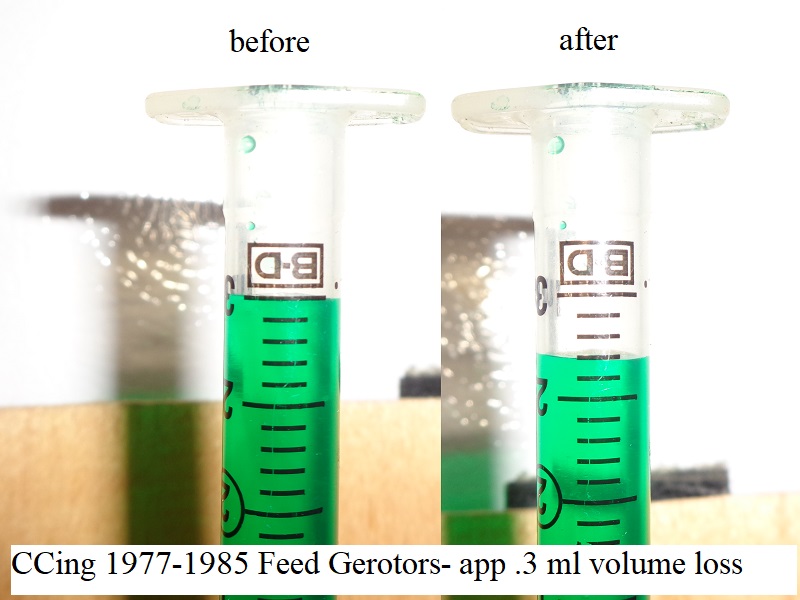
The 3 ML syringe was discarded and a .5 ML syringe with the included plunger was used instead.
The .5 ML syringe is graduated in .01 ML increments which takes a lot of the guessing out as to actual liquid level.
The tighter resolution with this syringe kept the guessing at the liquid level to a very minimum.
The results were much closer when comparing the two 1977-1985 gerotor set volumes together.
Using the smaller syringe, both cavity results changed slightly and the ratio between them squared up more.
Feed volume (.12 ML) x 2.785515320334262 = (0.3342618384401114 ML) and return tooth volume was .33 ML.
Now the difference between overall volume and overall height is 0.0042618384401114 which is a tighter margin of error.
Units of Measure / Formulas
Volume of a cube is the total cubic units occupied by it, in a three-dimensional space. 23)
A cube is a 3d-shape, that has six faces, twelve edges and eight vertices. Hence, the volume of a cube is the space enclosed by it's six faces.
Therefore, the volume of cube is equal to the product of its length, width and height.
It is measured in (as) cubic units. The more the value of it's dimensions, the more is the volume of it's cubic area.
Since the gears and gerotor teeth are not straight (compound angles and shapes), doing the math gets more complicated.
So instead of drawing lines and doing multiples of mathing, the act of determining volume between the teeth is done here by liquid volume.
The volume of the liquid in a tooth cavity is the result of overall geometry of the cavity and represents the length width and height of the cavity.
Therefore, the volume is automatically represented as in cubic units.
- To find volume of one tooth cavity, measure the area (L x W x D) (or in this case, find the volume in cubic inches (CI³).
- To convert milliliters to cubic centimeters, the ratio is 1 to 1 (1 ML = 1 cubic CM (CM³)).
- To convert cubic centimeters to cubic inches, divide cubic CM by 16.387064 (IN³ = CM³ ÷ 16.387064).
- To determine total volume of 1 pump revolution in CI³, add up the number of tooth cavities in 1 pump rev (8 cavities) and multiply that by volume of 1 tooth in IN³.
- To determine total pump volume per/ X RPM, multiply total volume in CI³ of 1 pump rev by RPM measured (RPM x total volume of 1 pump rev = total pump volume per minute in CI³).
- To convert cubic inches per minute to gallons per minute, divide the total volume by 231, US method, (total pump volume in cubic inches per minute / 231 = GPM).
- To convert gallons to ounces, multiply gallons by 128 (1 gallon = 128 ounces)
- To convert from centimeter of mercury (cmHg) to pounds per sq. inch (psi), multiply cmHg x 0.19336721269578
The Process
- Determine the volume of oil that one full tooth cavity contains in cubic inches (CI³).
- Determine the volume of oil that is delivered for one full pump revolution in CI³ (total volume of tooth cavities per 1 pump rev).
- Multiply that figure by pump speed in RPM to get total volume of oil delivered in CI³.
The Sportster oil pump (except XR-750) operates at 1/2 engine speed.
So idle at 1000 RPM for the engine is only 500 RPM for the oil pump. - Divide that figure by 231 (US) to find total gallons per minute the pump cavities are capable of delivering (GPM per RPM).
- Subtract pumping loss (internal leakage / slippage) to find total GPM pump is delivering.
Internal leakage through the clearances is an evolving figure based on clearance widths and viscosity.
Determining the amount of slippage has to be done with other experiments per pump.
A pump with tighter or looser clearances will yield different results.
Oil at room temperature (high vis) will produce less internal leakage than oil at operating temp (low vis).
So for the purpose here, we'll leave pumping loss for another day.
You have to be careful reading literature on pumping loss as centrifugal pumps will have more pumping loss than tight clearance rotary pumps.
And worn rotary pumps will have more slippage than rotary pumps in spec.
Result Summaries
Sub Documents
…….* Click Here for a chart containing these figures plugged into the full RPM range per gear set.
Again, these numbers are absolute (as long as the volumes were calculated properly) in the fact that The Pump Won't Flow Anymore Than What is Listed Per RPM.
Figures are 100% pump efficiency at best and these pumps do not run at 100% pump efficiency.
The greater the RPM, the more flow will be achieved.
This does NOT take into account normal or excessive internal oil leakage within the oil pump.
So real world GPM will be lower than what is listed here.
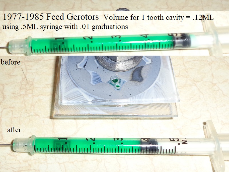
- 1977-1985 Gerotor Volumes
- Overall Feed Volume = 0.121 GPM (US) (or 15.49 oz/minute, US) at engine speed of 1000 RPM (pump speed 500 rpm)
- Overall Return Volume = 0.346 GPM (US) (or 44.29 oz/minute, US) at engine speed of 1000 RPM (pump speed 500 rpm)
- 1986-1990 Gerotor Volumes
- Overall Feed Volume = 0.185 GPM (US) (or 23.67 oz/minute, US) at engine speed of 1000 RPM (pump speed 500 rpm)
- Overall Return Volume = 0.346 GPM (US) (or 44.29 oz/minute, US) at engine speed of 1000 RPM (pump speed 500 rpm)
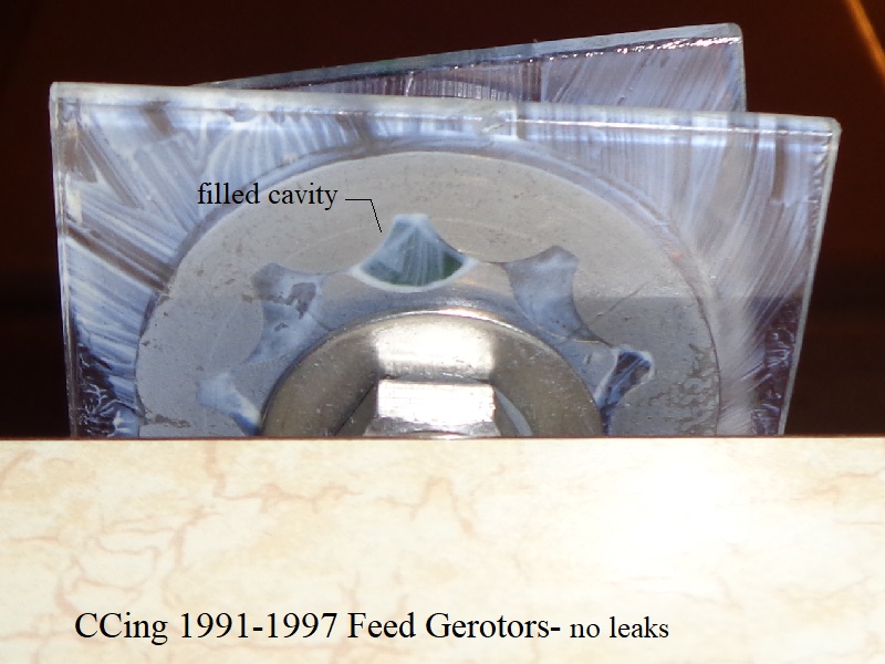
- 1991-1997 Gerotor Volumes
- Overall Feed Volume = 0.185 GPM (US) (or 23.67 oz/minute, US) at engine speed of 1000 RPM (pump speed 500 rpm)
- Overall Return Volume = 0.346 GPM (US) (or 44.29 oz/minute, US) at engine speed of 1000 RPM (pump speed 500 rpm)
- 1998-2006 Gerotor Volumes
- Overall Feed Volume = 0.185 GPM (US) (or 23.67 oz/minute, US) at engine speed of 1000 RPM (pump speed 500 rpm)
- Overall Return Volume = .485 GPM (US) (or 62.08 oz/minute, US) at engine speed of 1000 RPM (pump speed 500 rpm)
- 2007-Present Gerotor Volumes
- Overall Feed Volume = 0.180 GPM (US) (or 22.99 oz/minute, US) at engine speed of 1000 RPM (pump speed 500 rpm)
- Overall Return Volume = 0.782 GPM (US) (or 100.090 oz/minute, US) at engine speed of 1000 RPM (pump speed 500 rpm)
Results
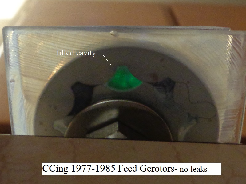
1977-1985 Gerotors
Using 0.5ML syringe (graduated in .01 ML increments);
Error Factor This Test
Comparing height vs volume of feed and return gerotors:
The cavities in both feed and return gerotors have the same geometry with the only difference being the height.
The feed gerotor height (.1795“) x 2.785515320334262 = the return height (.500”).
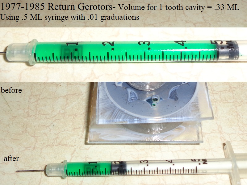
Feed volume (.12 ML) x 2.785515320334262 = (0.3342618384401114 ML) with the return tooth volume being 0.33 ML.
The difference is a volume over-result of 0.0042618384401114 ML when comparing height vs volume of the two gerotor sets.
Feed Gerotors
Gerotor Height = 0.1795”
Gerotor Volume = 0.121 GPM (US) (or 15.49 oz/minute, US) at engine speed of 1000 RPM (pump speed 500 rpm):
- One tooth cavity holds app (0.12 ml) of volume or (0.12 cubic centimeters) or (.007 cubic inches).
0.12cm³ = .007 ci³ volume (0.12 / 16.387064). - Volume of eight tooth cavities per 1 pump revolution = 0.056 cubic inches (.007 ci³ x 8)
- Total pump volume at engine speed of 1000 RPM (500 RPM pump speed) = 28 cubic inches per minute (.056 ci³ x 500)
- Feed pump volume at engine speed of 1000 RPM (500 RPM pump speed) = .121 gallons per minute (28 ci³ per minute / 231)
- Feed pump volume in ounces at engine speed of 1000 RPM (500 RPM pump speed) = 15.49 (.121 gallons per minute x 128)
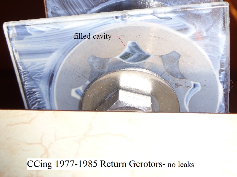
Return Gerotors
Gerotor Height = 0.500“
Gerotor Volume = 0.346 GPM (US) (or 44.29 oz/minute, US) at engine speed of 1000 RPM (pump speed 500 rpm):
- One tooth cavity holds app 0.33 ml of volume or (0.33 cubic centimeters) or (.020 cubic inches).
0.33cm³ = .020 ci³ volume (0.33 / 16.387064). - Volume of eight tooth cavities per 1 pump revolution = 0.16 cubic inches (.020 ci³ x 8)
- Total pump volume at engine speed of 1000 RPM (500 RPM pump speed) = 80 cubic inches per minute (.16 ci³ x 500)
- Return pump volume in GPM at engine speed of 1000 RPM (500 RPM pump speed) = .346 gallons per minute (80 ci³ per minute / 231)
- Return pump volume in ounces at engine speed of 1000 RPM (500 RPM pump speed) = 44.29 oz per minute (.346 gallons per minute x 128)
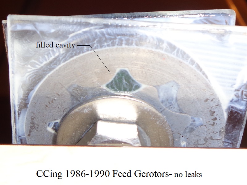
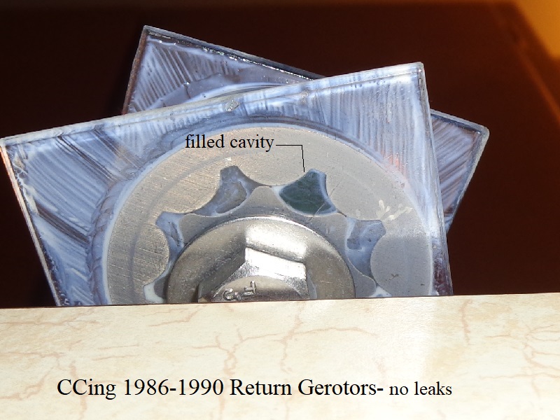
1986-1990 Gerotors
Using 0.5ML syringe (graduated in .01 ML increments);
Error Factor This Test
Comparing height vs volume of feed and return gerotors:
The cavities in both feed and return gerotors have the same geometry with the only difference being the height.
The feed gerotor height (.265”) x 1.886792452830189 = the return gerotor height (.500“).
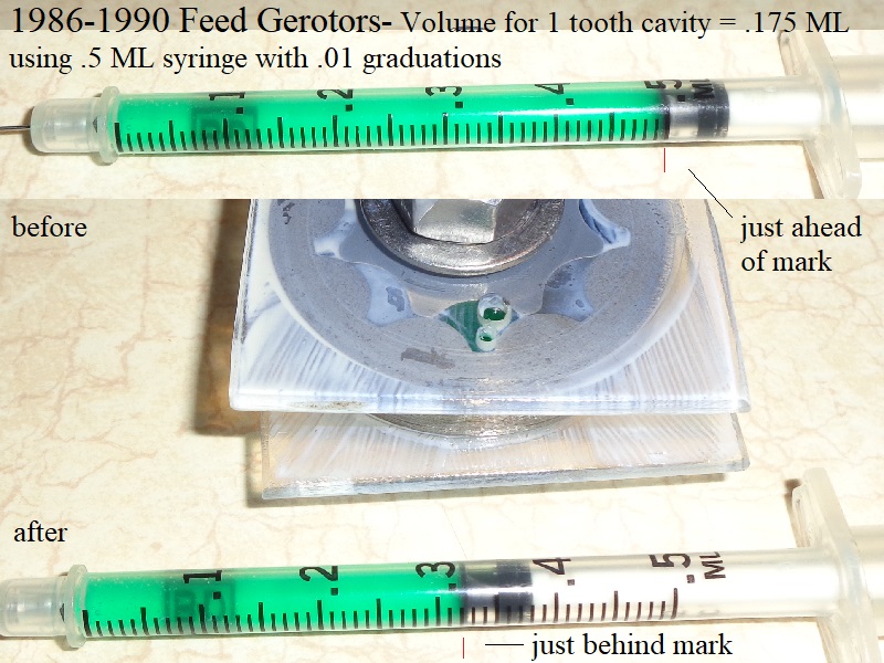
Feed volume (.175 ML) x 1.886792452830189 = (0.3301886792452831) with the return tooth volume being 0.33 ML.
The difference is a volume over-result of 0.0001886792452831 ML when comparing height vs volume of the two gerotor sets.
Feed Gerotors
Gerotor Height = 0.265”
Gerotor Volume = 0.185 GPM (US) (or 23.67 oz/minute, US) at engine speed of 1000 RPM (pump speed 500 rpm):
- One tooth cavity holds app (0.175 ml) of volume or (0.175 cubic centimeters) or (0.0106791552165781 cubic inches).
0.175cm³ = 0.0106791552165781 ci³ volume (0.175 / 16.387064). - Volume of eight tooth cavities per 1 pump revolution = 0.0854332417326252 cubic inches (0.0106791552165781 ci³ x 8)
- Total pump volume at engine speed of 1000 RPM (500 RPM pump speed) = 42.7166208663126 cubic inches per minute (0.0854332417326252 ci³ x 500)
- Feed pump volume at engine speed of 1000 RPM (500 RPM pump speed) = 0.1849204366507039 gallons per minute (42.7166208663126 ci³ per minute / 231)
- Feed pump volume in ounces at engine speed of 1000 RPM (500 RPM pump speed) = 23.6698158912901 (0.1849204366507039 gallons per minute x 128)
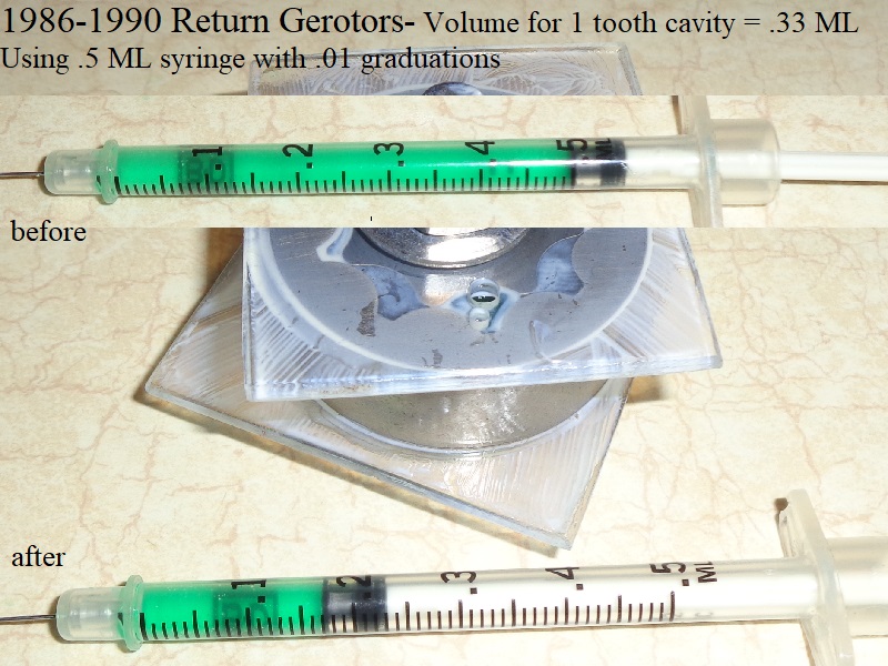
Return Gerotors
Gerotor Height = 0.500“
Gerotor Volume = 0.346 GPM (US) (or 44.29 oz/minute, US) at engine speed of 1000 RPM (pump speed 500 rpm):
- One tooth cavity holds app 0.33 ml of volume or (0.33 cubic centimeters) or (.020 cubic inches).
0.33cm³ = .020 ci³ volume (0.33 / 16.387064). - Volume of eight tooth cavities per 1 pump revolution = 0.16 cubic inches (.020 ci³ x 8)
- Total pump volume at engine speed of 1000 RPM (500 RPM pump speed) = 80 cubic inches per minute (.16 ci³ x 500)
- Return pump volume in GPM at engine speed of 1000 RPM (500 RPM pump speed) = .346 gallons per minute (80 ci³ per minute / 231)
- Return pump volume in ounces at engine speed of 1000 RPM (500 RPM pump speed) = 44.29 oz per minute (.346 gallons per minute x 128)
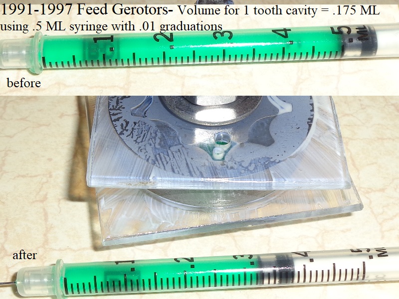
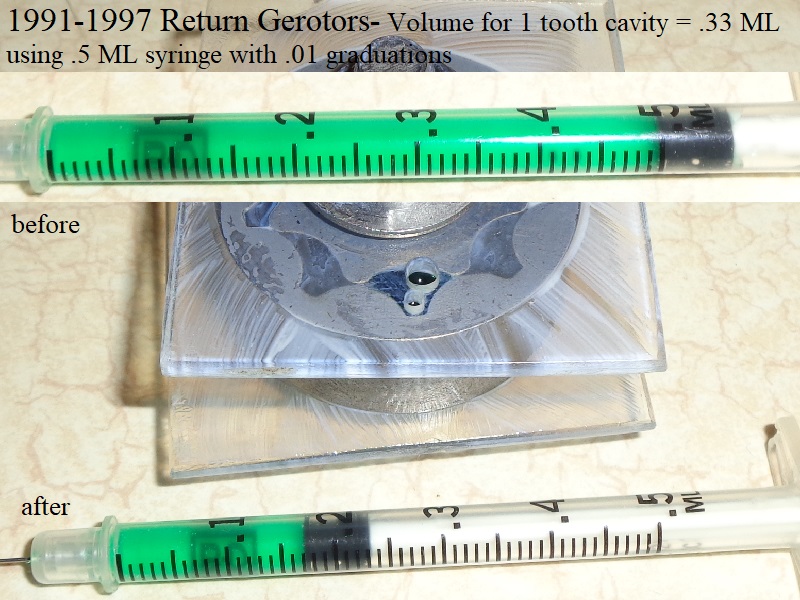
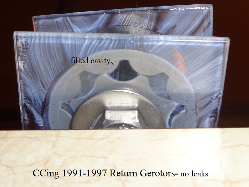
1991-1997 Gerotors
Using 0.5ML syringe (graduated in .01 ML increments);
Both the feed and return cavities have the same volume ratios as 1986-1990 gerotors.
Feed sets are the exact same except for a smaller inner gear ID for the gearshaft.
Return sets are the exact same between the gears but the OD of the outer return gear is smaller and the smaller inner gear ID for the gearshaft.
Error Factor This Test
Comparing height vs volume of feed and return gerotors:
The cavities in both feed and return gerotors have the same geometry with the only difference being the height.
The feed gerotor height (.265”) x 1.886792452830189 = the return gerotor height (.500“).
Feed volume (.175 ML) x 1.886792452830189 = (0.3301886792452831) with the return tooth volume being 0.33 ML.
The difference is a volume over-result of 0.0001886792452831 ML when comparing height vs volume of the two gerotor sets.
Feed Gerotors
Gerotor Height = 0.265”
Gerotor Volume = 0.185 GPM (US) (or 23.67 oz/minute, US) at engine speed of 1000 RPM (pump speed 500 rpm):
- One tooth cavity holds app (0.175 ml) of volume or (0.175 cubic centimeters) or (0.0106791552165781 cubic inches).
0.175cm³ = 0.0106791552165781 ci³ volume (0.175 / 16.387064). - Volume of eight tooth cavities per 1 pump revolution = 0.0854332417326252 cubic inches (0.0106791552165781 ci³ x 8)
- Total pump volume at engine speed of 1000 RPM (500 RPM pump speed) = 42.7166208663126 cubic inches per minute (0.0854332417326252 ci³ x 500)
- Feed pump volume at engine speed of 1000 RPM (500 RPM pump speed) = 0.1849204366507039 gallons per minute (42.7166208663126 ci³ per minute / 231)
- Feed pump volume in ounces at engine speed of 1000 RPM (500 RPM pump speed) = 23.6698158912901 (0.1849204366507039 gallons per minute x 128)
Return Gerotors
Gerotor Height = 0.500“
Gerotor Volume = 0.346 GPM (US) (or 44.29 oz/minute, US) at engine speed of 1000 RPM (pump speed 500 rpm):
- One tooth cavity holds app 0.33 ml of volume or (0.33 cubic centimeters) or (.020 cubic inches).
0.33cm³ = .020 ci³ volume (0.33 / 16.387064). - Volume of eight tooth cavities per 1 pump revolution = 0.16 cubic inches (.020 ci³ x 8)
- Total pump volume at engine speed of 1000 RPM (500 RPM pump speed) = 80 cubic inches per minute (.16 ci³ x 500)
- Return pump volume in GPM at engine speed of 1000 RPM (500 RPM pump speed) = .346 gallons per minute (80 ci³ per minute / 231)
- Return pump volume in ounces at engine speed of 1000 RPM (500 RPM pump speed) = 44.29 oz per minute (.346 gallons per minute x 128)
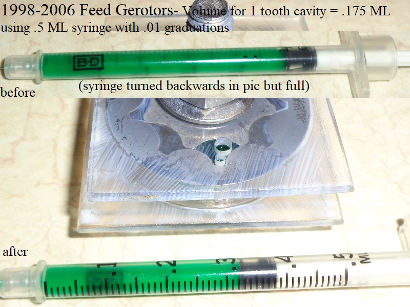
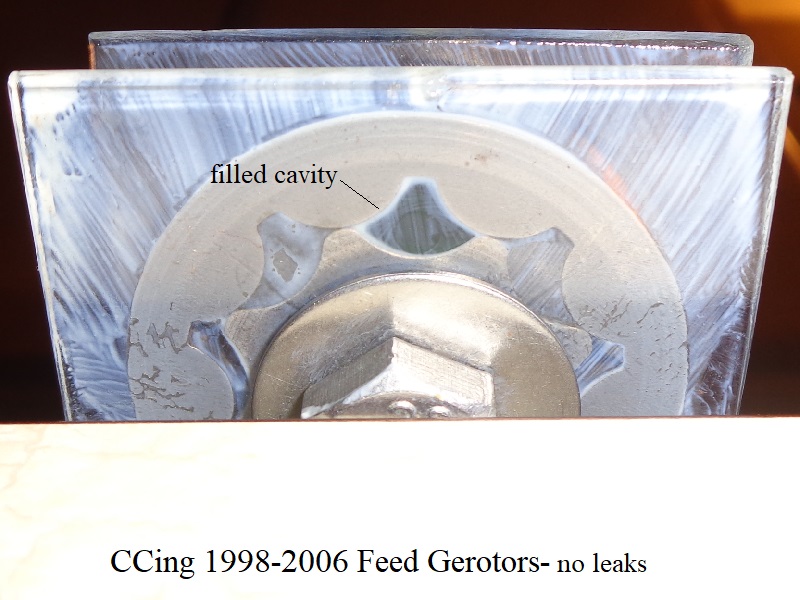
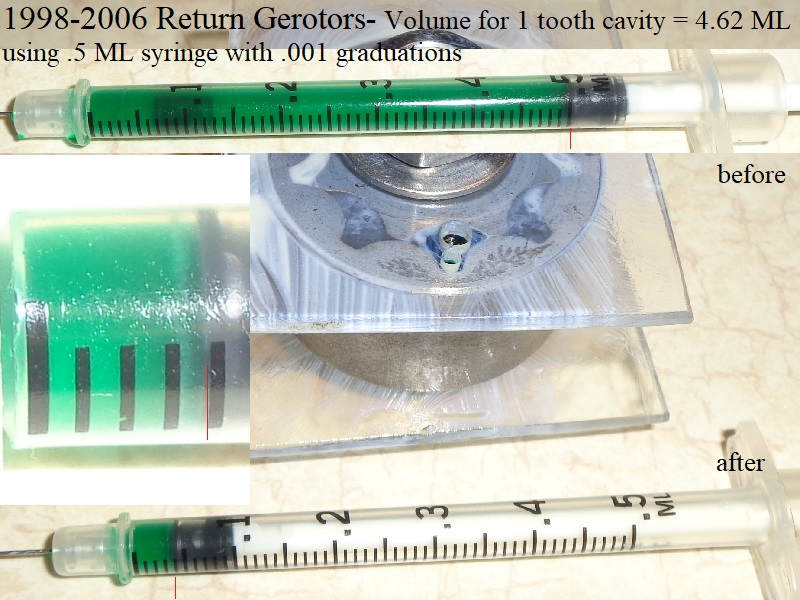
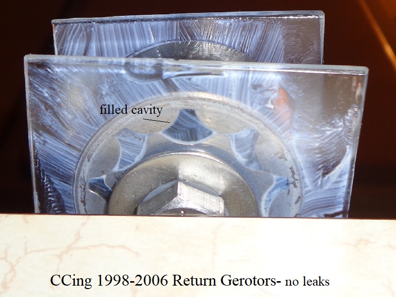
1998-2006 Gerotors
Using 0.5ML syringe (graduated in .01 ML increments);
Error Factor This Test
Comparing height vs volume of feed and return gerotors:
The cavities in both feed and return gerotors have the same geometry with the only difference being the height.
The feed gerotor height (.265”) x 2.641509433962264 = the return gerotor height (.700“).
Feed volume (.175 ML) x 2.641509433962264 = (0.4622641509433962) with the return tooth volume being 0.462 ML.
The difference is a volume over-result of 0.0022641509433962 ML when comparing height vs volume of the two gerotor sets.
The resolution between the final marks is very difficult to measure. Clearly there was more volume than the (4.6) mark in 4 separate tests.
Each time it was just a tad over. The best pics were used to show the results. The margin from .460 - .462 is left to interpretation here.
But .462 ML is used for the calculations below.
Feed Gerotors
Gerotor Height = 0.265”
Gerotor Volume = 0.185 GPM (US) (or 23.67 oz/minute, US) at engine speed of 1000 RPM (pump speed 500 rpm):
- One tooth cavity holds app (0.175 ml) of volume or (0.175 cubic centimeters) or (0.0106791552165781 cubic inches).
0.175cm³ = 0.0106791552165781 ci³ volume (0.175 / 16.387064). - Volume of eight tooth cavities per 1 pump revolution = 0.0854332417326252 cubic inches (0.0106791552165781 ci³ x 8)
- Total pump volume at engine speed of 1000 RPM (500 RPM pump speed) = 42.7166208663126 cubic inches per minute (0.0854332417326252 ci³ x 500)
- Feed pump volume at engine speed of 1000 RPM (500 RPM pump speed) = 0.1849204366507039 gallons per minute (42.7166208663126 ci³ per minute / 231)
- Feed pump volume in ounces at engine speed of 1000 RPM (500 RPM pump speed) = 23.6698158912901 (0.1849204366507039 gallons per minute x 128)
Return Gerotors
Gerotor Height = 0.700“
Gerotor Volume = .485 GPM (US) (or 62.08 oz/minute, US) at engine speed of 1000 RPM (pump speed 500 rpm):
- One tooth cavity holds app 0.462 ml of volume or (0.462 cubic centimeters) or (.028 cubic inches).
0.462cm³ = 0.028 ci³ volume (0.462 / 16.387064). - Volume of eight tooth cavities per 1 pump revolution = 0.224 cubic inches (.028 ci³ x 8)
- Total pump volume at engine speed of 1000 RPM (500 RPM pump speed) = 112 cubic inches per minute (.224 ci³ x 500)
- Return pump volume in GPM at engine speed of 1000 RPM (500 RPM pump speed) = .485 gallons per minute (112 ci³ per minute / 231)
- Return pump volume in ounces at engine speed of 1000 RPM (500 RPM pump speed) = 62.08 oz per minute (.485 gallons per minute x 128)
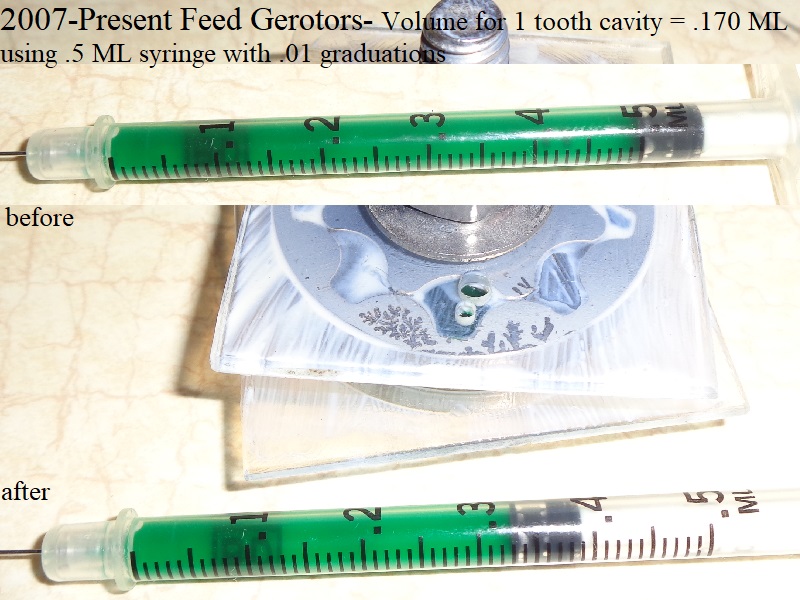
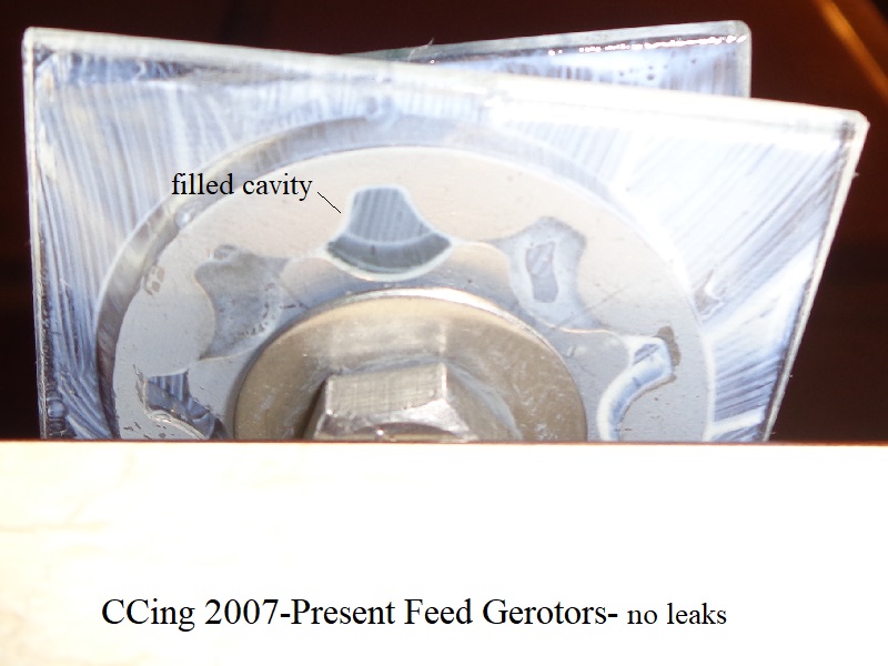
2007-Present Gerotors
Using 0.5ML syringe (graduated in .01 ML increments);
Error Factor This Test
Comparing height vs volume of feed and return gerotors:
The cavities in both feed and return gerotors have the same geometry with the only difference being the height.
The feed gerotor height (.200”) x 4.25“ = the return gerotor height (.850”).
Feed volume (.170 ML) x 4.25 = (0.7225) with the return tooth volume being 0.740 ML.
The difference is a volume over-result of 0.0175 ML when comparing height vs volume of the two gerotor sets.
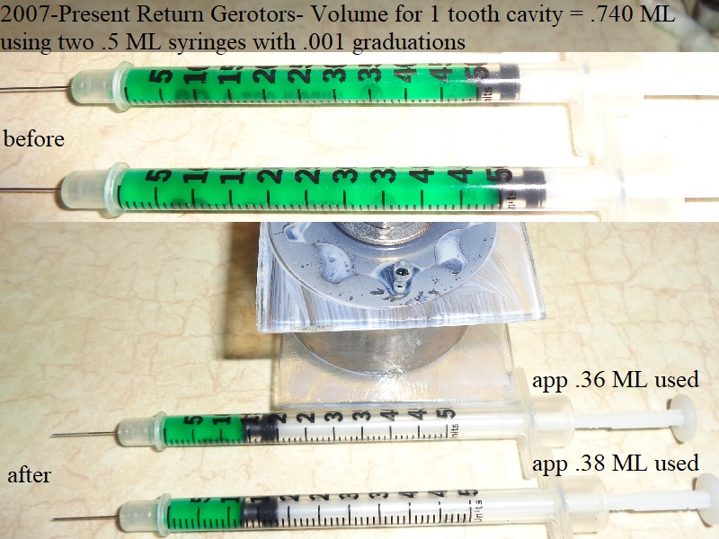
This could easily be due to using two syringes instead of 1 plus eyesight but a 10 ML syringe was also used on the return set with the same results (app.740“).
So with multiple testing and syringes, the results were about the same.
Feed Gerotors
The same syringe as for previous year sets was originally used on the 07 feed pump gerotors.
However, the return gerotors required 2 syringes and a different brand scale was used for them.
So the test was repeated for the feed side using a new syringe matching that used for the return gerotors.
The result was the same for the feed side using the 2 different syringes.
Gerotor Height = 0.200”
Gerotor Volume = 0.180 GPM (US) (or 22.99 oz/minute, US) at engine speed of 1000 RPM (pump speed 500 rpm):
2007-up gerotors have wider teeth profiles than previous years.
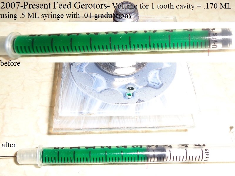
- One tooth cavity holds app (0.170 ml) of volume or (0.170 cubic centimeters) or (0.0103740364961045 cubic inches).
0.170 cm³ = 0.0103740364961045 ci³ volume (0.170 / 16.387064). - Volume of eight tooth cavities per 1 pump revolution = 0.0829922919688359 cubic inches (0.0103740364961045 ci³ x 8)
- Total pump volume at engine speed of 1000 RPM (500 RPM pump speed) = 41.49614598441795 cubic inches per minute ( 0.0829922919688359 ci³ x 500)
- Feed pump volume at engine speed of 1000 RPM (500 RPM pump speed) = 0.1796369956035409 gallons per minute (41.49614598441795 ci³ per minute / 231)
- Feed pump volume in ounces at engine speed of 1000 RPM (500 RPM pump speed) = 22.99353543725324 (0.1849204366507039 gallons per minute x 128)
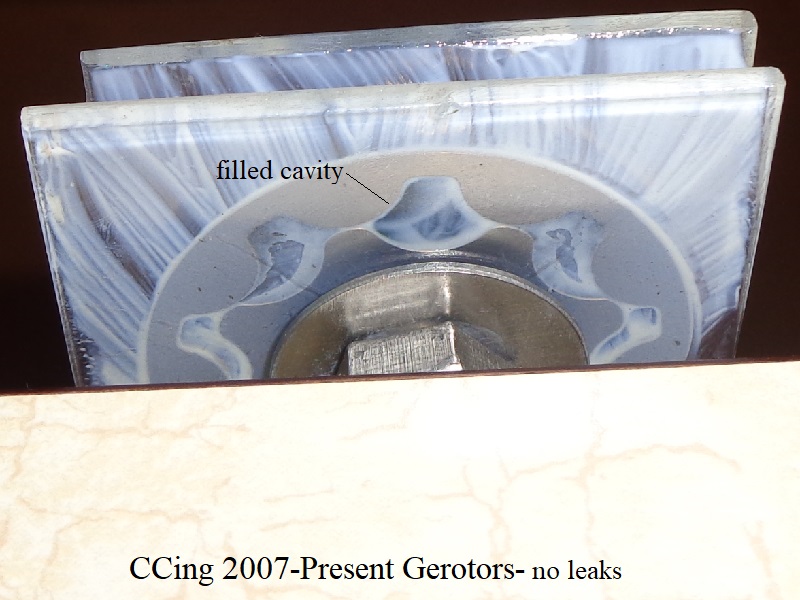
Return Gerotors
Gerotor Height = 0.850“
Gerotor Volume = 0.782 GPM (US) (or 100.090 oz/minute, US) at engine speed of 1000 RPM (pump speed 500 rpm):
- One tooth cavity holds app 0.740 ml of volume or (0.740 cubic centimeters) or (0.0451575706301019 cubic inches).
0.740 cm³ = 0.0451575706301019 ci³ volume (0.740 / 16.387064). - Volume of eight tooth cavities per 1 pump revolution = 0.3612605650408151 cubic inches (0.0451575706301019 ci³ x 8)
- Total pump volume at engine speed of 1000 RPM (500 RPM pump speed) = 180.6302825204076 cubic inches per minute (0.3612605650408151 ci³ x 500)
- Return pump volume in GPM at engine speed of 1000 RPM (500 RPM pump speed) = 0.7819492749801193 gallons per minute (180.6302825204076 ci³ per minute / 231)
- Return pump volume in ounces at engine speed of 1000 RPM (500 RPM pump speed) = 100.0895071974553 oz per minute (0.7819492749801193 gallons per minute x 128)
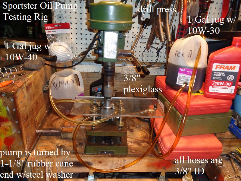
Flow Testing the Oil Pump
Equipment Used
3/8” plexiglass was cut, drilled for 3/8“ mounting bolts to the drill press and 1/4” holes to mount the pump.
An 1-1/2“ hole drilled thru the center for the oil pump gearshaft to slip thru.
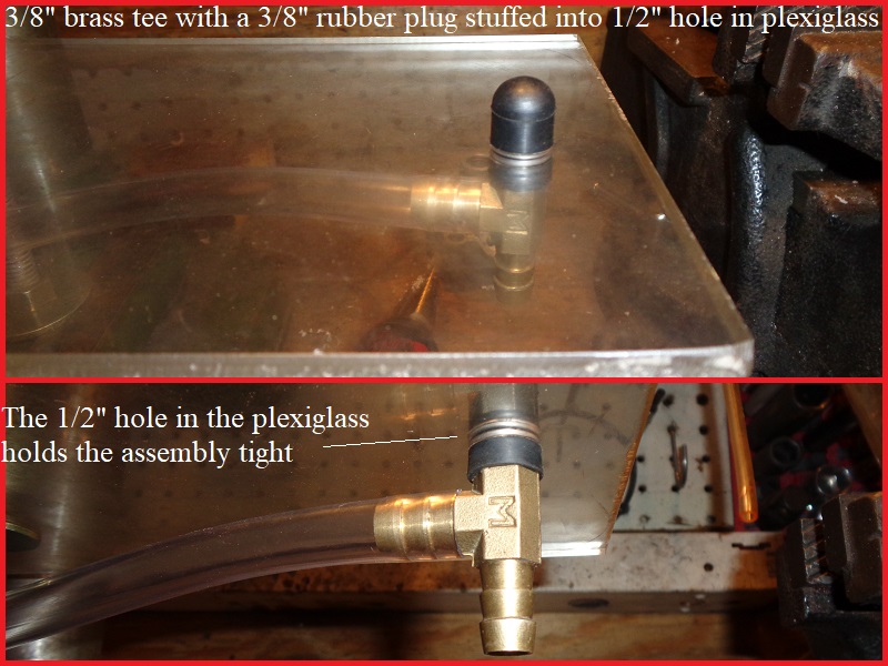
An 1/8” NPT hole tapped over the return duck bill and a 1/2“ hole on the right side to stuff a 3/8” tee and 3/8“ rubber cap into.
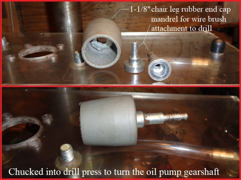
The rubber cup is a 1-1/8” Pivit, Heavy-Duty Walker, Commode and Bath Bench replacement rubber tip with a reinforcing metal washer inside.
The washer center and end of rubber tip were drilled to accept a mandrel for the drill press.
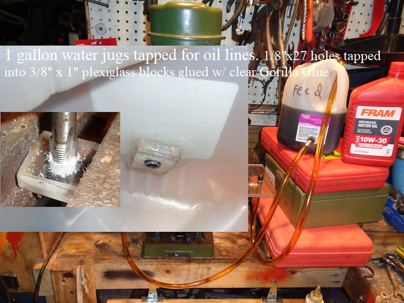
(2) 1 gallon plastic jugs with the tops cut out were originally used a mock oil tank and crankcase sump.
The jugs were drilled for 1/8“ NPT x 3/8” hose barb fittings to slide thru and screw into 3/8“ plexiglass block tapped 1/8” NPS.
The high above bottom position proved to leave too much oil in the jugs during flow testing and were later replaced with a paint bucket and an oil drain container.
All tubing is 3/8“ clear hose accept for the 1/4” hose to the vacuum gauge.
Various fittings were used to complete the plumbing, some moved, or removed / replaced.
A vacuum gauge was installed inline with both the feed and return inlets with a 60 PSI pressure gauge on the feed outlet hose.
Paint mixing buckets were used to measure output volume.
Mods for 1998 style pump:
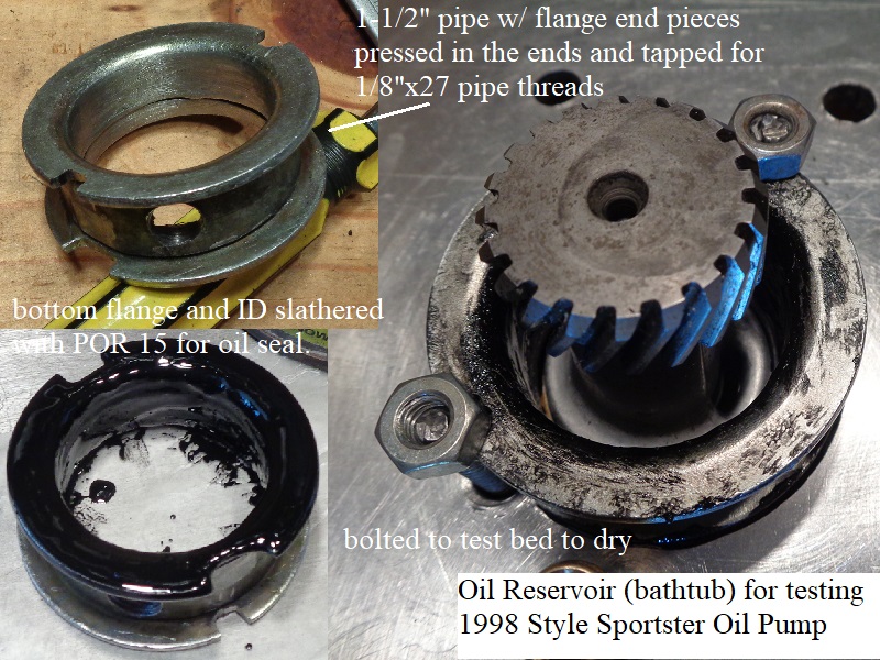
A reservoir (or bathtub) was constructed to feed oil to the cam port inlet in the top of the pump.
A short piece of 1-1/2“ pipe was cut and and finished on the ends with cut pieces of flange paipe pressed into the 1-1/2” pipe.
Then the joints inside were sealed with 5 minute epoxy followed by POR 15 on the bottom and inside to seal the bathtub to the aluminum bed.
A tap was made in the side of the pipe for a 1/8“ NPT x 3/8” hose bibb fitting.
Notable Issues
- Have plenty of rags on hand to clean up oil spills from handling / transferring hoses and parts.
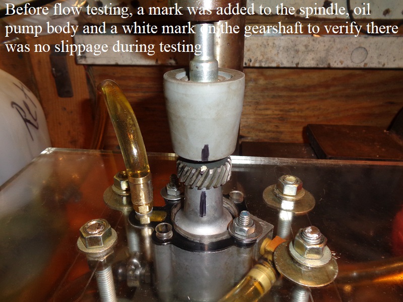
- The rubber mandrel works well as it is 1-1/8“ wide and the pump gear is app 1.20” so it stretches over the gear.
It can slip if you get oil on the gearshaft so markings were added on the gear, rubber cap and pump housing to verify it didn't slip after a test. - The 3/8“ plexiglass worked fine but initial test run showed an air leak between the plate and the pump gasket due to 91-up pumps only having 2 mounting bolts.
The diagonal corners not bound with a pump mounting bolt were flexing just enough to allow air in but not enough to show an oil leak (see Initial Test Run video below).
The mounting bolts/nuts for the plate were massaged enough to bring the flex back out (to counter the affects of mounting the pump and stop the air leak.
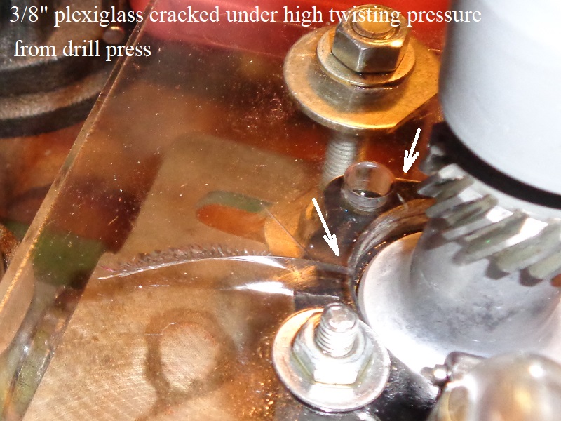
(see update test run video below). - First test of the day after test#7 below cracked the plexiglass plate due to high viscosity of the oil.
With the drill press on high speed (for first test of the day), oil was too thick and the higher torque cracked the plate.
RPM measurement should have been 2500-2600, but instead, the thicker oil brought that down 554 RPM on initial startup creating extra torque to crack the plate.
Equipment Test Run Videos
Bench Runs of Normal Operation
These videos are of the different pumps set up as normal with 2 containers (1 simulating the tank, 1 simulating the crankcase sump).
Oil tank piping: Tank oil to the pump and return from the pump are in the container on the right.
Motor piping: Feed oil to the motor and sump oil to the pump are in the container to the left.
In this video, app. 40 ounces of oil is in the “sump” container with the return hose to the pump and the feed hose from the pump inserted.
The 40 ounces is app. what might be in the crankcase on initial startup as reported by XLF members doing their own scavenging oil change.
Click Here for more information on performing a scavenging oil change. in the Sportsterpedia.
The sumped oil is eventually removed by the pump and air and oil are then pumped out continuously as it should normally in real time.
However, the video does not take into account the affects of crankcase pressure.
Some Positive crankcase pressure (piston downstroke) is expelled out the return passage to the pump (when oil is not present in the passage).
When oil is pulled away from the sump scavenge port, Positive crankcase pressure also pushes oil toward the return port where the pump re-establishes suction.
Then the pump pulls that oil up and out until the pool is too small to grasp, then air comes back into the return passage.
| 1991-1997 Sportster Oil Pump Bench Run 63) |
Flow Rate Result Summaries
- 1991-1997 Oil Pump
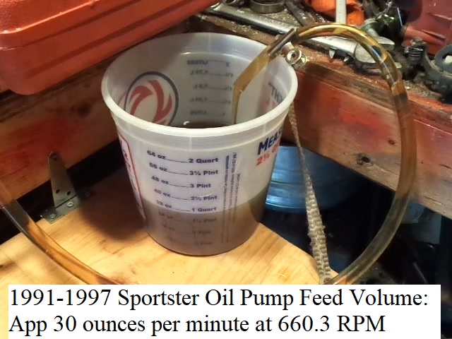
- Feed Volume at pump speed of 660.3 RPM: 30 ounces per minute
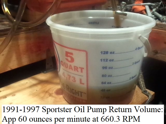
- Return Volume at pump speed of 660.3 RPM: 60 ounces per minute
Flow Results per Pump
1991-1997 Oil Pump Flow Test
Drag on Power Source
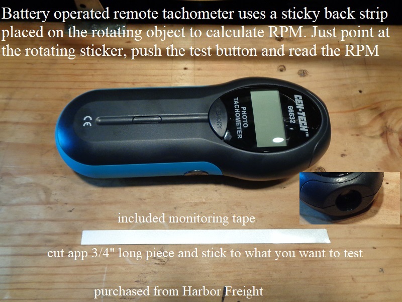
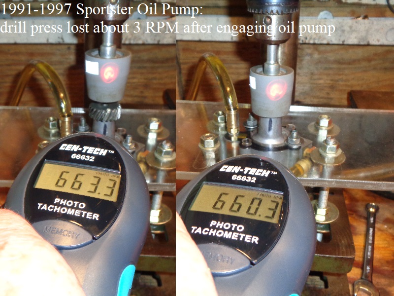
On low speed, the oil pump robbed about 3 RPM from the drill press during operation tested with a photo tach from Harbor Freight.
As the drill press speed was increased, the drag created by the oil pump was even greater.
 64)
64)  65)
65)
Feed Testing
Comparing the flow test to the previous calculations (CCing the gerotors);
Volume of eight tooth cavities per 1 pump revolution = 0.0854332417326252 cubic inches (0.0106791552165781 ci³ x 8)
Total pump volume at pump speed of 660.3 RPM = 56.41156951605242 cubic inches per minute ( 0.0854332417326252 ci³ x 660.3)
Feed pump volume in GPM at pump speed of 660.3 RPM = 0.2442059286409196 gallons per minute (56.41156951605242 ci³ per minute / 231)
Feed pump volume in Ounces Per Minute at pump speed of 660.3 RPM = 31.25835886603771 Oz (0.2442059286409196 gallons per minute x 128)
Actual Pump Feed Flow Test:
The video below shows about 30 ounces per minute into the container at 660.3 RPM.
(which is very close to 31.26 Oz from recalculating volume at 660.3 RPM as previously done on these gerotors).
The video was cut at the 1 minute mark (easier than trying to line up marks and times and stuff when viewing)
The pump started at the 18 sec mark and the video was cut at the 1m-18sec mark.
Return Testing
Comparing the flow testing to the previous calculations (CCing the gerotors);
Volume of eight tooth cavities per 1 pump revolution = 0.16 cubic inches (.020 ci³ x 8)
Total pump volume at pump speed of 660.3 RPM = 105.648 cubic inches per minute (.16 ci³ x 660.3)
Return pump volume in GPM at pump speed of 660.3 RPM = 0.4573506493506494 gallons per minute (105.648 ci³ per minute / 231)
Return pump volume in Ounces Per Minute at pump speed of 660.3 RPM = 58.54088311688312 oz per minute (105.648 gallons per minute x 128)
Actual Pump Return Flow Test:
The video below shows about 60 ounces per minute into the container at 660.3 RPM.
(just over the 58.54 Oz from recalculating volume at 660.3 RPM as previously done on these gerotors)
The video was cut at the 1 minute mark. Oil hit the bucket at the 18 sec mark and the video was cut at the 1m-18sec mark.
1998-2006 Oil Pump Flow Test
Feed Testing
Actual Pump Feed Flow Test:
The video below shows about 29 ounces per minute into the container at 653.7 RPM.
| Video: 1998-2006 Feed Volume at 660.3 RPM 70) |
Return Testing
Plugging the Sump Port:
Flow testing was done separately on the sump port and the cam chest port.
The sump port hose was capped off to find how much oil just the cam port inlet would deliver.
Next, the sump port was uncapped and left open to atmosphere.
There was no significant change in cam chest port output volume either capped or open.
However, with the sump port capped and 50 cmHg of vacuum still forming in the sump cavity itself from the gerotors, entrained air was present in the oil delivered.
With the sump port open to atmosphere, there were just pockets of air and oil delivered.
Actual Pump Return Flow Test
Flow testing was done measuring volume of the sump inlet port (cam port open to atmosphere) and cam inlet port (sump port open to atmosphere).
Then a third test was done including both inlet ports.
- The cam port alone inlet delivered about 16 ounces per minute into the container at 654.3 RPM.
- The sump port alone delivered about 43 ounces per minute into the container at 654.3 RPM.
- Both the sump and cam ports together delivered about 71 ounces per minute.
- Total projected volume from the return gerotors (CCing gerotors) was 62.08 oz/minute at pump speed 500 rpm.
So the flow test results are comparable although higher than projected due to higher pump speed. - As long as both return inlets are getting oil, volume picked up and returned to the tank is a little higher.
It seems these two inlets complement each other.
And in reverse, if oil is not flowing as fast to one or the other port, total volume back to the tank is lower.
- The individual flow volumes add up to the cam chest inlet port delivering 27.1% of the flow (16 + 43 = 59), (16 / 59 = .2711864406779661 or 27.1%)
It's not known from which or both inlets that the extra 12 ounces of oil came from when they were tested together.
| 1998-2006 Return Test Video Both Ports Delivering Oil 71) |
2007-Present Oil Pump Flow Test
Feed Testing
Actual Pump Feed Flow Test:
The video below shows about 30 ounces per minute into the container at 654.7 RPM.
| Video: 2007-Present Feed Volume at 654.7 RPM 74) |
Return Testing
Actual Pump Return Flow Test:
Flow testing was attempted to measure volume of the sump inlet port (cam port open to atmosphere) and cam inlet port (sump port open to atmosphere).
- The cam port volume could not be tested due to not enough oil being delivered to it.
First, the container of oil for the cam chest inlet was hung above the drill press where the inlet hose was 25-1/2” above the pump (oil level 28“ above pump).
The oil pump had more suction than the weight of gravity oil (more suction than gravity could deliver oil for).
Next, the container was raised to where the inlet fitting was 34-1/2” above the pump with the oil level at 39“ above.
The oil pump was still sucking faster than the oil was being delivered to the top of the pump. - The sump port alone delivered about 63 ounces per minute into the container at 654.7 RPM.
Further Testing Attempted
Feed Pressure Testing
- Restrictions were added on the outlet hose of the feed side on a 1991-1997 oil pump.
(to check for internal oil leakage and volume changes per restriction size)
It was found that the added restrictions lowered the speed of the drill press and thus lowered output volume.
There is no way to tell if internal leakage or lower RPM was the cause of lower output volume. So in conclusion, testing for this phase is a fail.
The video below shows the 3 tests that were done.
| 1991-1997 Oil Pump- Restrictions Video 77) |
Static Pressure Testing
- 1991-1997 oil pump static pressures: Feed outlet fitting ID was changed for three tests which lowered RPM on the drill press.
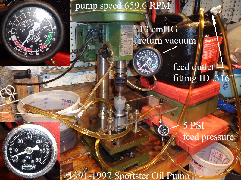
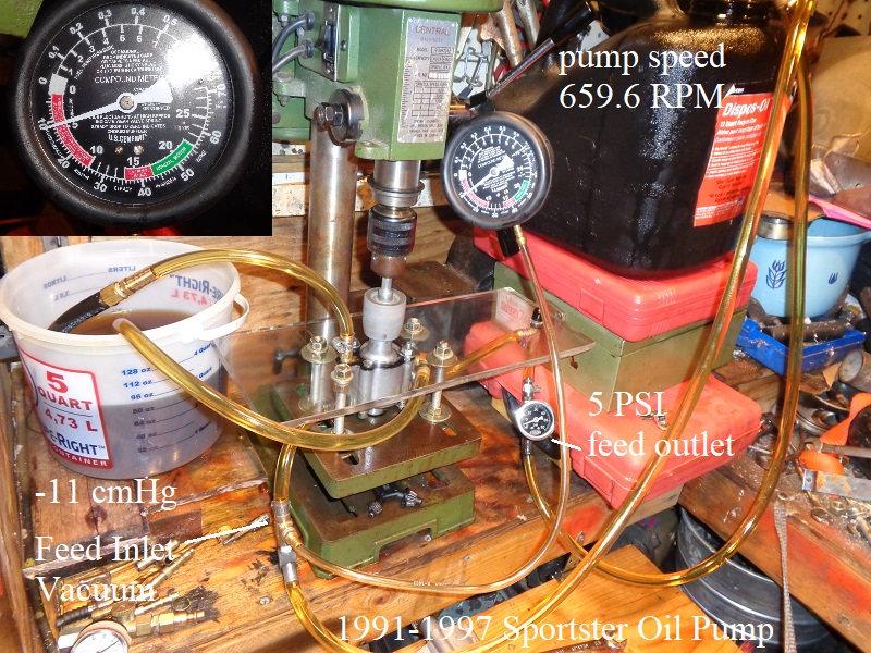
- Test #1 at pump speed of 659.6 RPM and feed outlet fitting ID of 0.316”;
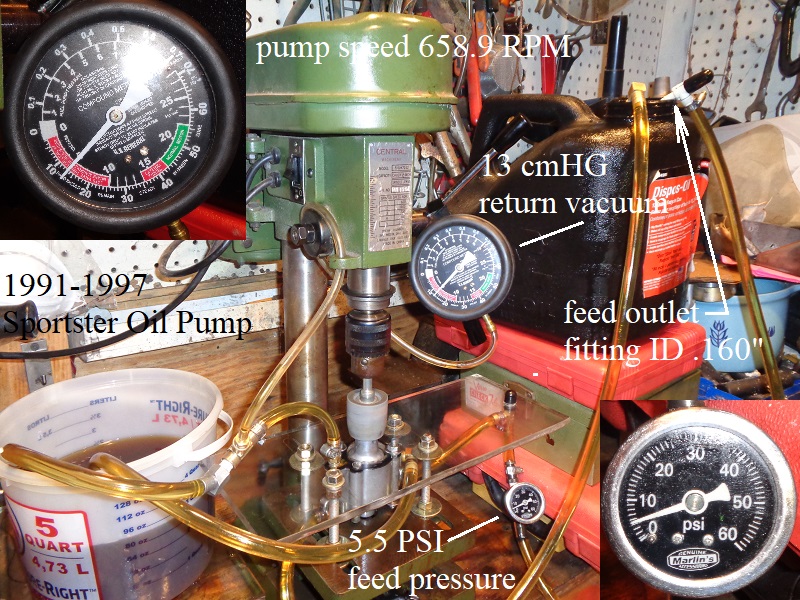
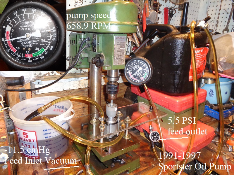
Feed Outlet Hose Pressure (5 PSI), Feed Inlet Hose Vacuum (-11 cmHg or -2.13 PSI), Return Inlet Hose Vacuum (-13 cmHG or -2.51 PSI) - Test #2 at pump speed of 658.9 RPM and feed outlet fitting ID of 0.160“;
Feed Outlet Hose Pressure (5.5 PSI), Feed Inlet Hose Vacuum (-11.5 cmHG or -2.22 PSI), Return Inlet Hose Vacuum (-13 cmHg or -2.51 PSI) - Test #3 at pump speed of 654.7 RPM and feed outlet fitting ID of 0.110”;
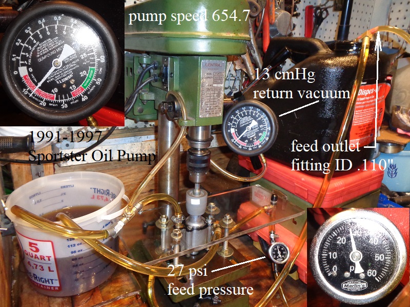
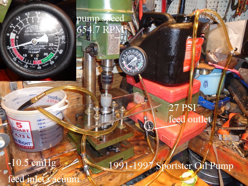
Feed Outlet Hose Pressure (27 PSI), Feed Inlet Hose Vacuum (-10.5 cmHg or -2.03 PSI), Return Inlet Hose Vacuum (-13 cmHg or -2.51 PSI) - Test #4 at pump speed of 1142 RPM and feed outlet fitting ID of 0.316“;
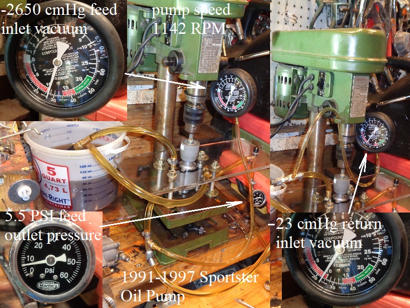
Feed Outlet Hose Pressure (5.5 PSI), Feed Inlet Hose Vacuum (-26.5 cmHg or -5.12 PSI), Return Inlet Hose Vacuum (-23 cmHG or -4.45 PSI) - Test #5 at pump speed of 1697 RPM and feed outlet fitting ID of 0.316”;
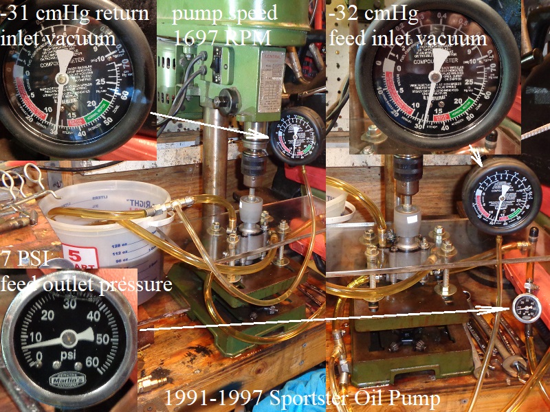
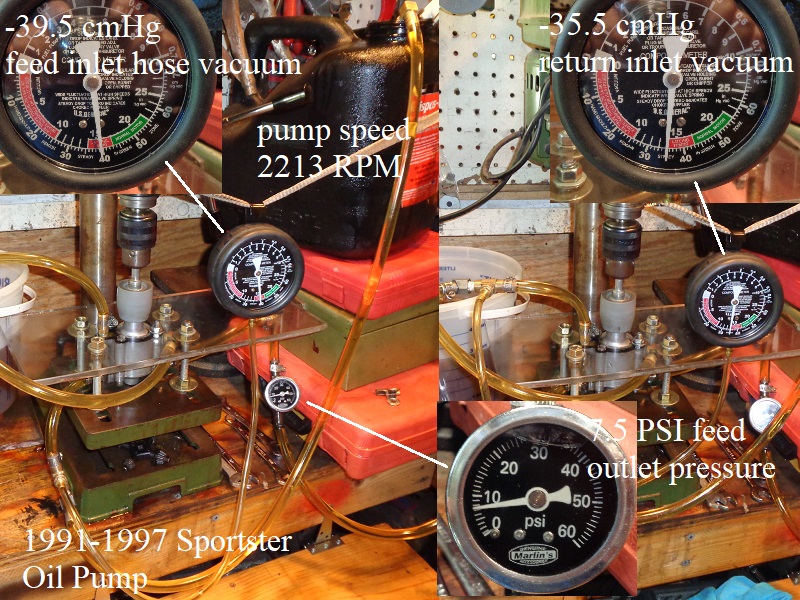
Feed Outlet Hose Pressure (7 PSI), Feed Inlet Hose Vacuum (-32 cmHg or -6.19 PSI), Return Inlet Hose Vacuum (-31 cmHG or -5.99 PSI) - Test #6 at pump speed of 2213 RPM and feed outlet fitting ID of 0.316“;
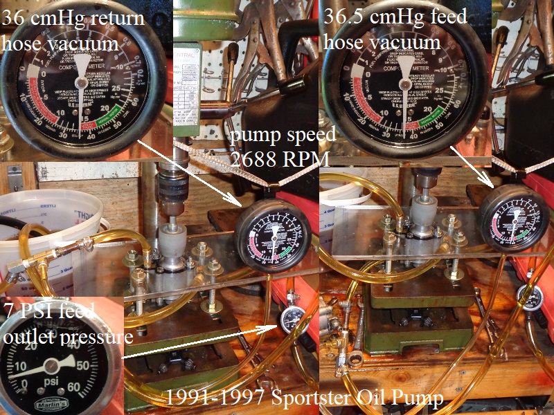
Feed Outlet Hose Pressure (7.5 PSI), Feed Inlet Hose Vacuum (-39.5 cmHg or -7.64 PSI), Return Inlet Hose Vacuum (-35.5 cmHG or -6.86 PSI) - Test #7 at pump speed of 2688 RPM and feed outlet fitting ID of 0.316”;
Feed Outlet Hose Pressure (7 PSI), Feed Inlet Hose Vacuum (-36.5 cmHg or -7.06 PSI), Return Inlet Hose Vacuum (-36 cmHG or -6.96 PSI)
- 1998-1999 oil pump static pressures:
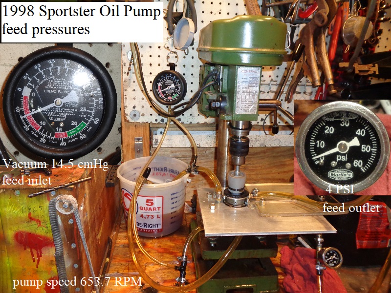
- Test at pump speed of 653.7 RPM and feed outlet fitting ID of 0.316“;
Feed Outlet Hose Pressure (4 PSI), Feed Inlet Hose Vacuum (-14.5 cmHg or -2.80 PSI),
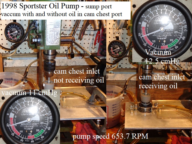
Return Inlet Hose Vacuum Without Oil in the Cam Chest Inlet Port (-11 cmHG or -2.13 PSI)
Return Inlet Hose Vacuum With Oil in the Cam Chest Inlet Port (-12.5 cmHG or -2.42 PSI)
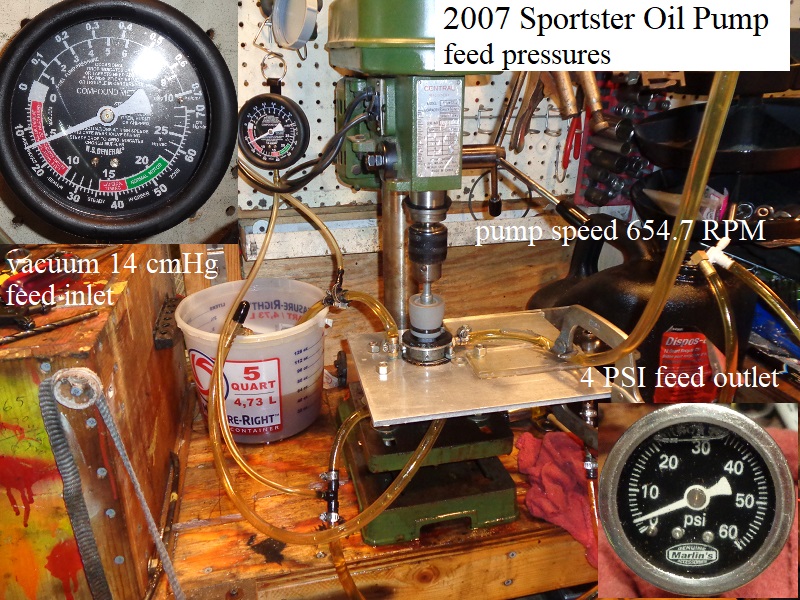
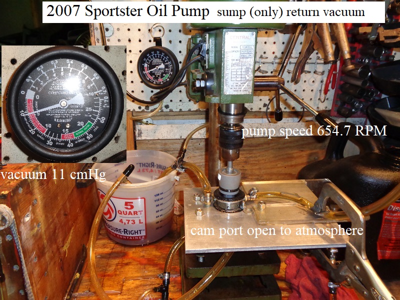
- 2007-Present oil pump static pressures:
- Test at pump speed of 654.7 RPM and feed outlet fitting ID of 0.316”;
Feed Outlet Hose Pressure (4 PSI), Feed Inlet Hose Vacuum (-14 cmHg or -2.71 PSI),
Return Inlet Hose Vacuum Without Oil in the Cam Chest Inlet Port (-11 cmHG or -2.13 PSI)
Return Inlet Hose Vacuum With Oil in the Cam Chest Inlet Port not tested.
| 1991-1997 Pump Pressure Test #1 | |
 |  |
| 1991-1997 Pump Pressure Test #2 | |
 |  |
| 1991-1997 Pump Pressure Test #3 | |
 |  |
| 1991-1997 Pump Pressure Test #4 | 1991-1997 Pump Pressure Test #5 |
 |  |
| 1991-1997 Pump Pressure Test #6 | 1991-1997 Pump Pressure Test #7 |
 |  |
| 1998-2006 Pump Feed Pressure Test | 1998-2006 Pump Return (sump hose) Pressure Test |
 |  |
| 2007 Pump Feed Pressure Test | 2007 Pump Return (sump hose) Pressure Test |
 |  |
Return Inlet Restrictions
Testing was done on a 1991-1997 oil pump to see what affect restricting the return passage from the sump to the pump would have.
The inlet hole in the oil pump below the duck bill was enlarged twice over time giving a total of 3 different inlet hole sizes.
1977-1990 return inlet hole ID = 0.250“
1991-1997 return inlet hole ID = 0.280”
1998-Present return inlet hole ID = 0.350“
| 1977-present oil pump return inlet holes 78) |
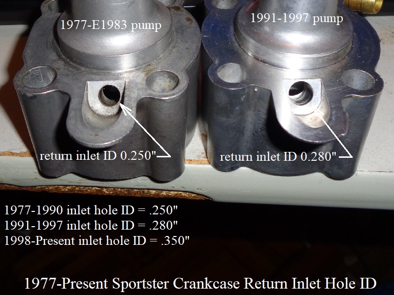 |
It appears the inlet holes were not sized to add more volume, but rather to reduce the possibility of cavitation.
- In the first video below, the inlet hose from jug to pump was squeezed down (restricted it) at different vacuum points.
All the way to 50 cmHg, the volume sucked out of the bucket was about the same per each 10 cmHg increment (more or less) but nothing significant.
So the pump will suck app. the same volume of oil from the sump (as long as oil is available) no matter how hard it has to work to get it.
But the harder it has to work, the more vacuum it creates in the return passage to the pump.
The more vacuum that is created, the easier it is to pick up bubbles from the oil leading to cavitation of the pump in some form.
The greater the heat, the easier it is to pick up oil vapors leading to destructive cavitation. Oil temp during this testing was 88°F.
Noise is the first sign of cavitation followed by vibration, then detonation.- The video shows that increasing or decreasing the inlet hole size would not amount to any significant volume change from the pump.
However, the gains from increasing the hole size does reduce the amount of vacuum exerted along the return path from the sump to the pump.
If that 50+ cmHg holds in real world experience in the motor, then any more vacuum than that can begin to cavitate the return side of the pump.
- In the second video below, testing was done at different RPMs and restrictions to find some evidence of cavitation.
The pump experienced sizzling noises from low RPM-high vacuum, vibration from higher RPM-high vacuum and grinding gravel noise from higher RPM-high vacuum.
It seems that 50-55 cmHg of vacuum was the point at which problems began throughout the RPM range.
The drilled return passages from the sump to the pump in the motor are smaller than what was tested on the bench.
Smaller hose ID (matching the actual return passage ID) will result in increased vacuum. Longer hose length will also increase vacuum.- Air bubbles started to be pulled out of the oil around 50 cmHg and higher (-9.67 PSI).
It is assumed that the horizontal drilled passage to the pump was enlarged to match the pump inlet hole ID.
However, the vertical drilled passage leaving the sump would remain the same size as before the pump inlet was enlarged.
This is due to the need for the 1/8”x27 plug on the bottom of the case. That hole can only be enlarged to the pre-drill size the plug.
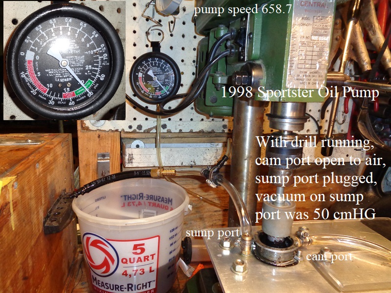
1998 Oil Pump Sump Passage Dead Stick Vacuum Test
- The sump port hose was plugged off with a vacuum gauge off the hose and the cam port was open to atmosphere.
The vacuum on the sump hose was a steady 50 cmHg.
Then oil was introduced into the cam port hole and the vacuum on the sump hose jumped higher and pegged the gauge.
Vacuum was in excess of 74 cmHg with the actual number not known.
The addition of oil traveling to the sump inlet cavity in the pump increased vacuum on the hose.
- Testing was done to see the oil quality change between having the sump port open to atmosphere and then the sump port plugged off.
Oil stream quality coming from the cam port inlet is different going out the return to tank line if the sump port is open to atmosphere or plugged.- With the sump port open to atmosphere;
Both air and oil were pumped thru the return hose.
The smaller cam port cavity delivers oil to the bigger sump cavity and air fills what's left in that cavity. - With the sump port plugged;
Both air and oil were still pumped thru the return hose.
However, the bigger sump cavity pulled a huge vacuum that sucked oil and air from the cam port inlet and entrained air and oil.
The second part of the video shows tight nit “lighter in color” air/oil mix traveling with the darker oil in segments.
Vacuum on the plugged off hose from the sump is 50 cmHg.
| 1998-2006 Style Pump Video Cam Port Stream Quality 83) |
—-
3)
, 4)
, 5)
, 6)
, 7)
, 8)
, 9)
, 12)
, 13)
, 14)
, 15)
, 16)
, 17)
, 18)
, 19)
, 20)
, 21)
, 22)
, 25)
, 26)
, 27)
, 28)
, 29)
, 30)
, 31)
, 32)
, 33)
, 34)
, 35)
, 36)
, 37)
, 38)
, 39)
, 40)
, 41)
, 42)
, 43)
, 44)
, 45)
, 46)
, 47)
, 48)
, 49)
, 50)
, 51)
, 52)
, 53)
, 54)
, 55)
, 56)
, 57)
, 58)
, 64)
, 65)
, 66)
, 68)
, 78)
, 81)
, 82)
photo by Hippysmack
24)
drawing by Hippysmack