Table of Contents
This is an old revision of the document!

REF: Shop Notes and Tips
4 Speed Transmission Removal / Inspection / Installation
This section is not meant to be a replacement to the FSM. It is meant as a compliment to the FSM or added information with pics that are not in the manual. Always buy an FSM and a Parts Catalog to help you along your maintenance path. The Haynes and Clymer brand service manuals for the most part will suffice and they generally have more pics than the HD Service manual. But, end result, there are discrepancies in all of them including the HD parts and service manuals.
Gear Spacing
- Measuring the spacing is tedious. With the trans assembled and fixed in a vice by the bottom edge of the trap door, ensure that none of the parts make contact with the vice while you are turning the gears. Try not to drop the trans on the floor too many times while setting this up To proceed, the trans must be firmly set up so that you can run it thru the gears. 1)
- To measure the gear spacing consistently hold the assembly in such a way that the gears do not move around while you are measuring. You have to press inward lightly on the end of the shafts or on the outermost gear, then ensure that they stay in place while you proceed. Hold the two parts that you are measuring so that they do not move while you are measuring. But do not be too aggressive with this keeping things from moving - you want to simulate what it will be like in a running setup. You do not want to cram them together, just do it enough that every time you do it you will get the same result. 2)
- So you need at least three hands, possibly more, one or two to hold the assembly from moving and changing the spacing while you are working, and another one or two to manage the feeler gauge. It can be done with just two though 3)
- There are only a few options in setting the spacing. I believe that the best you can do is to get somewhere in the range. The shift forks must be in place - one of the options to adjust spacing is to replace the shift forks with different sizes. 4)
Mainshaft
- On the mainshaft, measure between the tips of the dogs on 4th and the face of 2nd; and measure between the face of 3rd and the protrusion from 2nd. 5)
- When setting mainshaft clearances, shims have no effect on fork setting so this can be done in either order 6)
Countershaft
- On the countershaft measure the space between the tips of the dogs on 1st and the face of 3rd; and measure between the face of second and the protrusion from 3rd.
- When setting up clearances on the countershaft, especially if your current shift fork isn't getting you into tolerance and needs to be replaced with a different offset… 7)
- Do the fork spacing 1st, then shim for end play because on the counter shaft there are shims that go on both sides of c-shaft low gear (17t). 8)
- The shims (2 shims on 73> type gear, one on 72< speedo type gear) on left (shaft) side of 17t gear will affect fork spacing. So, you can use them to your advantage with forks. 9)
- When changing them for fork spacing after c-shaft has been shimmed in case will require you to re-shim in case for end play because you have changed the deck height of the c-shaft assembly. 10)
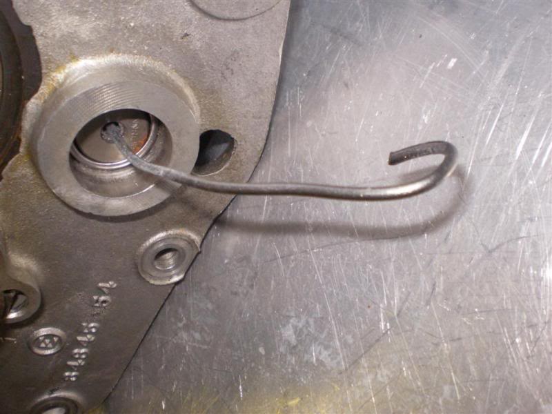
Countershaft and Oiler Plug
- Before installing the oiler plug, set it off to the side until after you've set / checked your final countershaft endplay. otherwise it'll be in your way. 18)
- The oiler plug should be a tight interference fit. It should go in and stay in with the engine running and vibrating and carrying on. Upon dis-assembly, many are found to be loose or rather the hole has probably been worn from the aluminum being smashed in and out of a few times without heating the aluminum trapdoor to expand it. This is why you should ALWAYS heat aluminum engine and gearbox casings, wheel hubs etc, with a propane torch before removing or installing bearings. Doing it cold works once, maybe twice, then the hole is worn out. 19)
- To fix a loose oiler plug, you can take the plug to a machine shop and get them to knurl it. That will increase the diameter by a few thousandths. Then re-install it with Loctite. I would use the red, it is the strongest. But you will then need to use a propane torch to break the Loctite to get it back out. 20)
- You can also peen the hole to retain the oiler. 21)
- Late '84 and up trap door does not include a countershaft oiler plug. When installed in this newer trapdoor in older applications, it may easily hit and scrubb the back of the stator due to being too long. It will either need to be machined down for your clearance measurements or the old style trapdoor must be used. 22)
| 4 Speed Trans Countershaft comparison 23) | Early style HD 4 Speed Trans Countershaft 24) | Oiler Plug in '77 tranny 25) |
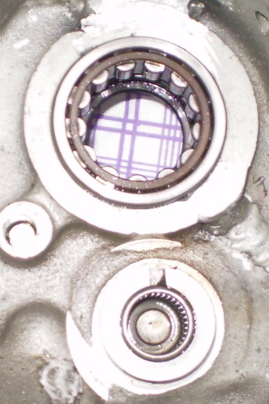
| Oiler Plug & Countershaft Needle Roller Bearing 26) |
Mainshaft & Countershaft Needle Bearings & Race
Removal
You should ALWAYS heat aluminum engine and gearbox casings, wheel hubs etc, with a propane torch before removing or installing bearings. Doing it cold works once, maybe twice, then the hole is worn out.27)
- Bearing Race Removal / Installation:
- To remove a badly worn mainshaft bearing race, remove the retainer ring (two thin blade screw drivers, one to get an end lifted/started and the other to get under the ring and work it around, and a lot of patience) 28) and washer. Discard the retainer ring. Heat case surrounding the bearing hole and drift new race inward from the outside of the case. Press new race in until shoulder is against case inner surface. Check specs for correct fit of mainshaft right side roller bearing. Install washer and new retainer ring. 29)
- Countershaft Bearings:
- For the countershaft bearings, select a socket (and extension) that just fits inside where the bearing is seated. Drive old closed end (and new) bearing from right to left with the socket/extension and a hammer using only light blows. The new bearing's max install depth is flush with outside of case (min depth is .030” left outside of case). For the trap door countershaft bearing, carefully remove the oiler plug without damaging the “snout”. Drive bearing out in the same manner with socket against printed end of bearing. Install new bearing 1/16“-3/32” below flush with inside edge of door. 30)
- Clutch Gear Bearing:
- Clutch gear bearing requires removing large snap rings, lightly hammer the clutch gear out with a small piece of wood between hammer and shaft. You can even thread the large nut on so it is on flush with the end of the shaft for support. Then the bearing needs to be pressed off. New bearing gets pressed onto the clutch gear until it is flush to the gear and install it into trap door. 31)
- An alternative for the needle bearing in the clutch gear: Find a washer that's the same size as the bearing and cut two flat places in the edge of the washer so it will pass through the bearing, turn it flat against the inside of the bearing and use a threaded piece of 5/16 rod through the bearing and washer, put nuts on each end of the rod and use a larger socket to pull it into. 32)
Installation
You should ALWAYS heat aluminum engine and gearbox casings, wheel hubs etc, with a propane torch before removing or installing bearings. Doing it cold works once, maybe twice, then the hole is worn out.33)
Hopper
- If you are using a new shaft and race, you will have to line hone or line lap the new race until 23 stock size rollers fit with the correct clearance. Needs to be done in line with the trapdoor bearing. Although someone on here did mention that Jims or someone makes a race that is to size and supposedly does not need line lapping to finish it off. Dunno about that. 34)
- Be sure to put the hardened flat washer BETWEEN the rollers and the spring circlip on the outside, or the rollers and the gap in the circlip will make a big mess of themselves. 35)
- You can assemble the mainshaft into the bearing without the rest of the tranny attached, then put on the sprocket and nut to hold it in place, then slide in the rest of the tranny. I forget which gear (or is it neutral?) to have the tranny in to make this easiest but if you play with it a bit it is fairly obvious which gear lets the mainshaft loose. 36)
trappnman
- You aren't going to be able to put them in place, with the tranny in. Be nice if you could, and it would be nice if HD would have fitted a sealed bearing or anything but those damn loose rollers but such is life….. 37)
- So try to put the rollers in by, as stated, greasing the race, then one by one putting them in place- adding more grease if needed to hold in place. 38)
- That last roller, will be a tight fit, but you should get it into place. If not, and only after a good hearted effort, go to honing. If needed its going to take a VERY little, so careful as you go. 39)
- As far as oversized rollers- you should have that information from wherever you purchased them from the invoice- if you didn't specify size, they would, I'd think be standard 40)
- A tip on putting tranny back through rollers (and unless you are a lucky pup, it might take a few tries, so all you can do is curse, and redo the rollers. to make it easier, make it a 2 man job, with one on one side sliding tranny into case- the other with a awl into the shaft hole on the other end to guide it straight. amazing how much easier it goes. 41)
brucstoudt
- Actually you can put the 23 mainshaft roller's in with the transmission in from the outside. The outer snap ring must be removed, and then reinstalled, after the roller's are in. I prefer to do it this way. I can SEE that they're all in place. 42)
- The outer retaining ring is not a snap ring with hole's for plier's that would make it so simple. It's the circlip type with slot's for prying.
- It's not bad coming out but going back in is tougher. I don't reuse them but I guess it surely wouldn't be the first time.
- Put the roller's at the bottom of the race in first [push up on shaft, slightly]. The end of the mainshaft sag's slightly with no support so if you try to put them in last, it will be tough.
Clearancing Rollers
- Any bearing using loose rollers or balls needs to have a gap left equivalent to about one roller or ball so the rollers/balls do not grind on each other. Check your workshop manual for proper number of rollers.
- If they are still tight, you will have to lap or hone a tiny bit out of the race to give the clearance specified in the workshop manual. I don't remember the exact figure but maybe somewhere about half to one- thousandth max.
- Don't run the bearing with zero clearance. It leaves no room for lubricant between rollers and race/shaft.
- Don't run the rollers crowded so they are jammed up to one another. They will not rotate correctly and will chew the living crap out of the race and shaft.
- Make sure you have that hardened flat steel washer between the spring circlip and the mainshaft rollers, otherwise the gap in the circlip chews up the rollers quicktime. 43)
Mainshaft Needle Bearings
- The standard size for the 23 loose mainshaft rollers is .1562“ 44).
- Question: When does fitting oversize rollers result in MORE running clearance? 45)
- Answer: when the same quantity of oversize rollers are fitted to a 'cageless full compliment bearing'. 46)
- Below are two true geometric constructions of 23 rollers. 47)
![]() 50)
Factory size of:
Main Race is 1.305 dia.51)
Mainshaft is .99152)
50)
Factory size of:
Main Race is 1.305 dia.51)
Mainshaft is .99152)
1957-Early 1982 Mainshaft Thrust Washer Roll Pin
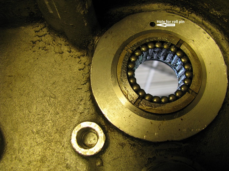
A roll pin is installed at the twelve o'clock position over the mainshaft hole to keep the spacers from spinning. The spacers on the end of the mainshaft have a tab that would hit the roll pin and lock in. If your mainshaft thrust washer has a tab, then it needs the roll pin. Otherwise it acts like an oil slinger, and them parts need that oil! Make sure to put the special hardened washer between the snap ring and the loose rollers.
- Roll pin from 1957 - Early 1982 #(600) and is 1/8” dia x 9/16“ long. It sticks out 3/16” +/- 1/32“ from the alum surface. 54)
- Always replace with a new roll pin, use a good thread lock when installing it. 55)
- NOTE: The mainshaft rollers are NOT lubricated by splash via the static ear washer. There is a curved oil collector on top of the mainshaft bearing that fills with oil being thrown around. The oil is then fed by gravity to the outside of the roller outer race via a hole located between outer case and the mainshaft oil seal. Then oil exits by gravity via the static ear washer. So, oil would still find its way out if it was spinning which questions the static bit of the logic of using the pin. I have run engines with and without the pin, doesn't seem to make much difference. 56)
Removing a sheared off roll pin
- Instead of removing the old one that is sheared off and flush with the case, drill another hole with a drill bit .003” under the pin diameter a few degrees around the bearing on the same radius as the existing pin. Press fit the new pin into the hole. You may want to try this using a scrap piece of metal to determine what size drill bit works best. Your object is to press the pin into a hole so tight that you cannot (easily) pull it out. When you find the correct size drill bit, put a drop of epoxy on the end of the pin then press it into the hole. You don't want loose pins dropping into the transmission. 57) A new pin (about ~ 1 o'clock) next to the old one.58)
- Hand drilling a straight hole is a bit difficult but what I would do is get a piece of wood and drill a straight hole through that using the bit you are going to drill the case with. Make the wood thickness such that the drill extended through it sticks out the same depth you want to drill. Then place the block of wood against the case and this will guide the bit into the aluminum fairly straight and to the correct depth all in one shot. 59) If the hole isn't dead straight it's not much of a problem. If the hole is over size that's not cool. Drill 3/32“ first. Then follow with 1/8”. This will help keep the hole size good. Don't drill thru. If you didn't drill deep enough, you can grind some length off the pin after installation. 60)
- After drilling, you might want to check on the outside of the case to see if a pilot hole came through.
- Another option is to drill through the pin hole to the outside of the case. Drill the pilot to just under the pin size and drift it out. The hole can be plugged with a machine screw. Also, there is no reason a longer machine screw could act as the stop. There is no loading on the pin so it would not take much to stop the rotation. The only drawback is it will probably fall on the shaft seal flange, but the screw can be applied on the outside of the flange or the flange drilled to allow the head to protrude. If this method is considered, use a allen head screw that is hardened as a regular machine screw is on the soft side. 61)
- Another option when drilling to the outside is to fill the outer access hole with good 'ol JB weld once a new roll pin is installed. 62)
Mainshaft Endplay
- The mainshaft bearing in the trap door slides back and forth between the snap rings. 63)
- When checking mainshaft endplay, you need to hold the bearing in the correct position for your clutch style. There are 3 clutch release styles: 64)
- Early dry clutch pushes from the right
- Middle wet clutch pushes from the left
- Late wet clutch pulls from the left.
- If the endplay is set without this in mind all of the clutch release pressure will go against the mainshaft trust washer and turn it blue. The end play you measure will open up when the clutch release moves the trap door bearing over and may cause shifting problems. 65)
- Trap door bearing position should also be set when shimming the trans and setting shift fork offsets. 66)
- You want the pressure on the whole clutch assembly pushing in on it. 67)
Countershaft Endplay
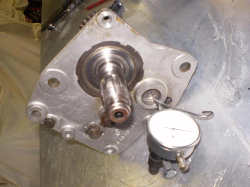 | 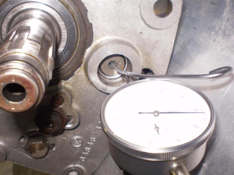 | 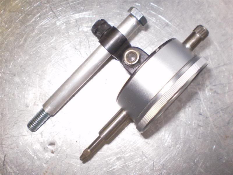 |
| Mock setup: obviously the box is not in the cases where it needs to be to do the job. But easier for pictures. NOTE ! You may be able to see the dial indicator stem is actually sitting on the countershaft bearing outer race - it needs to be sitting on the end of the shaft here, not on the bearing. 68) | A closer shot and here you can see the wire (bent) that is used to push and pull on the countershaft. The dial indicator is centered on zero of course before you start pushing and pulling. You can then read the endplay directly from the dial indicator. 69) | This is the dial indicator mounted on the alloy spacer with the bolt through it. The bolt just screws into the bottom tranny case mount hole on the left case half with the tranny sitting correctly in the engine. You will also need a selection of thrust washers to actually adjust the endplay to get it where it needs to be. 70) |
 |
| The really important bit - the bent wire. 71) |
Transmission Crankcase Repair
Trans Corner Reinforcement '54-'72
By Dr Dick of the XLFORUM, 72)
It's common knowledge that '72< bikes may have had their trans corner of right crankcase damaged and then fixed by welding everything back together. Sometimes those repair jobs are good quality, sometimes maybe not so good.
How to keep your original undamaged cases safe, that is if your lucky enough to have undamaged cases, and how to fix damaged cases correctly the 1st time.
- Some people may feel the case is so weak that it breaks from the power going through the transmission. I don't believe this is true.
- Years ago it was believed by some that the speedo drive adapter would shed its gear and then the broken off gear would get caught in the mesh of the power carrying gears, forcing shafts apart and busting cases at the right countershaft bearing boss. I don't share this view either.
- What i think happens is:
- When the power carrying tooth or dog or gear gets stressed enough to break in the trans, it gets caught between the meshing teeth of the power carrying gears which forces the shafts to separate. This overloads the counter shaft boss.
- The right side of the countershaft drops from the broken boss, (breaking off the speedo adapter gear) and then the crooked counter shaft cracks the trans door.
- With 2 pcs of shrapnel floating around, the original broken dog or tooth plus the now busted off speedo gear, you pull in the clutch and coast to the side of the road. With the rear chain still driving mainshaft rotation.
- The mainshaft tries to keep the misaligned countershaft spinning (which it does until the rear wheel stops turning). That delinquent countershaft continues to destroy everything it can sink its teeth into (most importantly your cases).
- If this happened to you, you would get to thinking;
- “Man I'd happily buy every trans component brand new without a whimper if my cases had endured this failure. It would be a ton better than fixing my trans and my cases.”
- It's impossible to completely remove the possibility of a broken power carrying component. The best you can do is the help your cases survive the above scenerio. And that is a BIG deal when your standing on the side of the road, lookin behind you, at a 2“ wide, 100 yard long trail of tears…. that mere seconds ago was your trans lube.
To that end I have reinforced many cases. Most of the time, they have endured the above scenerio. Rarely they haven't. It depends on how severe the inital explosion was.
- Because these old bikes get stripped down for parts way more often than they get resurrected, preserving the good ones is important to me. The fix described here will not allow trans driven speedo anymore so this is a reversible mod. It can be undone to bring a bike back to oem specs.
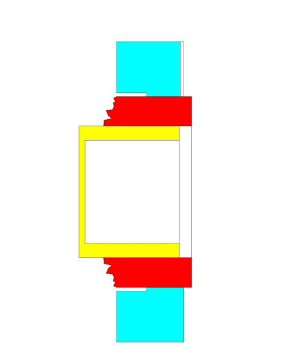
- A cross section view of the right crankcase at the countershaft boss.
- The 52-53 is the 1st iteration of the design. Each after that is noted as to the upgrade.
- And this is the most common mechanism failure (not the only failures, just the most common)
- The red is the broken areas. How long the countershaft continues to spin after this initial case failure determines how much worse the damage will become.
- The 73-76 cases are almost immune to this failure. It's rare to see them welded up. They can survive all but the worst case scenario. The 77-79 cases were slightly thinner. They break more often but still are stronger than the 72< design. Then around 1980 you start seeing cases busted badly again. They must be cast of lower quality material.
- When you hear of guys 'dehumping' 1000 cases for kick only models- what your really hearing is how to get the strongest foundation for your kick only. Its the strength of the 73-76 cases that makes all that work worth while.
* Before you assemble the ring to the case you need to remove any mushrooming or raised burrs due to cshaft thrust washer kissin on the face of the case boss.
- On Late 66>-72 cases this fix can be considered done. Early 66< cases are inherently weaker from the missing .125 fillet.
- The reinforcement rings:
- Doing the above is a big help and is advised but at times even with the ring installed, it will still fail as shown in the red pic.
- Optionally, you can go to the next level- you weld the ring so the ring becomes part of the case instead of part of the boss.
- Note that the welds are small enough that they can be removed to restore the original design. Some guys screw rings to the case with screws thru the .250 thick wall behind the ring instead of welding.
I've never done that but I have seen and worked on bikes setup like that. They seem to work ok. Are there any hidden problems with the screws? I don't know.
- The shown welding can also be done on the L66-72 although its not really necessary unless your boss is hairline cracked.
- When doing this mod keep press fit between the ring and unmolested boss O.D. to .003 in. max. Even a .0005 in. press fit is ok.
- To achieve this fit, the ring usually falls in the tolerance band indicated in the pics.
- If your boss is slightly damaged, shooting for the indicated ring bore size will get you back on the road.
- There are many different ways cases have been damaged, and there are many possible ways to fix them (some better suited than others).78)
- The replaced corner section or any repair where the weld beads stray off the surface surrounding the bearing bore will warp the case seam as described. I'd like to address this to guys who own bikes that this has been done to because this warpage may be present on your bike.
- One of the 'blank' areas is what happens after the fix is done.
- How reliable is the fix?
- What can I expect down the road?
- Let's look at those questions. You bring your case to the welder, a truly grade A welder. He welds it. You ask him those 2 questions. He can't answer them because he don't know jack about a 900.
- Same goes with the machine shop. You bring your case to a truly grade A craftsman. He machines it. You ask him those 2 questions. He cant answer them because he don't know jack about a 900.
- Where does that leave you, the owner? Blank. That's where.
- What you needed was a 900 shop that does their own welding and machining. A guy who can weld and machine around the idiosyncrasies of a 900 and hang his reputation on the fact he covered all bases needed for a permanent fix with no compromise and no worries on your part.
- There used to be lots of us. I guess that's not the case any more. I had done dozens of these before rich products introduced a replacement section and well over 100 since. I've used 3 different methods in regard to the warpage, depending on how much the owner wanted to sink into the repair.
- These are my observations:
- No warpage control at all: real world street use problems I've seen with this = zero. The left side case flexes to meet the warped right. This don't seem cool but it seems to work fine.
- Build up surf & re-machine. real world street use problems I've seen with this = zero.
- Flex right case opposite before welding, re-machine part surf and 3 motor mount pads surrounding studs: real world street use problems I've seen with this = zero. By far the cleanest most professional result but you need to be familiar with the exact way the case is gonna distort to make this an effective route.
More information
- I have done a set of cases with a thin metal ring made from the outer race for the mainshaft 23rollers. It's I.D. is slightly bigger than the boss. I seem to remember using a 5 thousandth in. shim to close the gap and obtain a press fit, plus stud Loctite to lock it in 79)
- For other cases, I've used alloy rings, with a slight vertical cut on the face to ensure the Torrington will receive enough oil… 80)
- For most guys with a small garage, welding and machining is not an option and can take the non welding route most of the time as far as cases are concerned if welding is not strictly necessary and can be avoided.
- A nicely light press fit helped with stud loctite will go a long way!!! My above mod on my KHK cases was done some 15 years ago at least, hasn't move a yota, suits me fine!!! But then, the crack was minimal and caught in good time before it got worse… 82)
- Seems like everybody does these a little different. I use a steel ring .0005” tight and install using locktite sleeve retainer (green). And yes,I have never had a problem- Street or strip. I do not like welding on the cases without them being torqued together unless it is absolutely necessary. The green locktite sleeve retainer is some very permanent stuff. 83)
- Red Loctite is High Strength thread locker , Green is bearing and sleeve retainer and typically for non-threaded apps . There are also two types of green: one is self wicking the other is meant to be applied before assembly. 84)
- Probably depends on what's available near you. If I had to do it myself I'd go the machined route, but where I used to live there were at least a dozen guys who were TIG-welding gods. Most of them could weld aluminum cans together and have it come out beautiful. I'd say that if you have Grade-AAA welders available and if you are equipped to touch up the cases afterwards, it's a better fix. But if not, the machined part is likely to give better results. 85)
- Apples and oranges barefoot:
- Apple: see a weakness - fix weakness 100%. These guys usually can because they have access to all the machinery needed and the expertise to make it happen. 86)
- Orange: bike is apart in my kitchen. I got no tig or mill. It's been together with the weakness for 50yrs. If I can bolt an improvement in without breaking the bank, that's an option. 87)
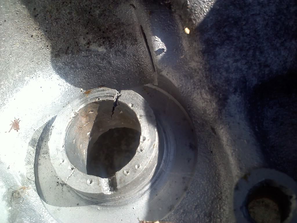
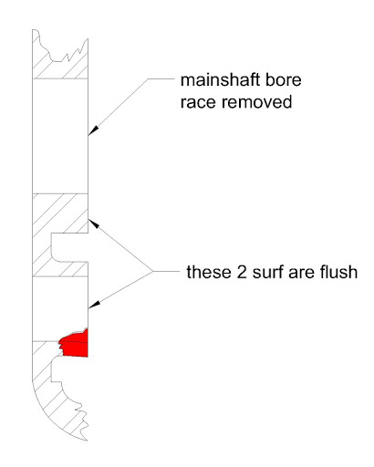
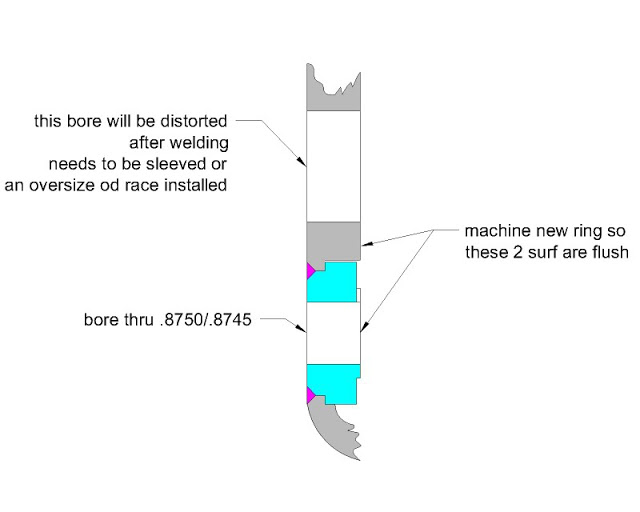
Mainshaft Bore Damage
By Dr Dick of the XLFORUM,88)
- An overly tight (I.D.) reinforcement ring pinching the needle bearing bore must be avoided.
- On L66-72 it will lead to bearing failure.
- On 54-early 66 unwelded rings this may be seen upon bearing replacement where the yellow is the bearing:
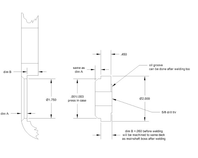
- Its hard, if not impossible, to get a measurement off the case boss O.D. I made up a set of gauging rings in .001 bore increment steps to find boss O.D. These gauging rings need to be long enough to be manipulated inside case.
- Then I shoot for .001- .002 press fit.
- Notice the stepped bore of the case around repair area. As time passed, I came to realize that its not too cool to put compressive forces on the boss so close to the case wall. I believe this adds more stress concentration to corner junction of boss and wall.
- Consider the .225 in. relief depth to be the minimum (.250 in. wont hurt).
Bore Boss Repair
- Not so bad. Of the different kinds of damage this is the easiest to repair and in my opinion results in a phenomenally tuff crankcase. I never seen one fail after what I'm going to describe. I have personally done this procedure many times. My '60ch 72“ is done like this. I hammer the hell out of that bike. 90)
- But 1st:
- When you weld you WILL get warpage that accompanies that welding. The more you weld the more warpage you will get. The underlying cause for this is: as metal changes temperature, it changes in size. 92)
- The temperature change in the weld is from molten to room temp. The temp change in the surrounding parent material is less. The parent material obviously cant be preheated to molten so there's a difference in size change between the welded and the case material. 93)
- This is the warpage.
- Sometimes repairing the warpage is a bigger job than the original repair (when money is being considered). So, getting the countershaft held firm without excessive welding and the warpage that accompanies it is the least intrusive to your cases and your wallet.
- What you got now. 94)
- The details: Ring 6061-T6 alum, filler rod 4043 alum.
- The 1.75 in. case bore will keep the weld away from the lower kicker cover bolt and dowel. It will also leave a 1/8 in. wide deck in the case that gives you a set height to work from. 96)
- This is the finished product: 98)
- This welding also needs to be done before reshooting bores. 100)
- This procedure results in no perceptible warpage at the case parting seams. this cant be said when the case corner is blown apart and a new cast corner piece is welded in. Obviously the outcome is dependent on quality of workmanship. When doing this work the time is right for making sure your door fits correct too. 102)
More Information
- After welding a support on the countershaft bearing bore, trap door to bore may need to be re-checked. If the bearing support as in the picture is that badly cracked, welding may be the only answer. 103)
- Case bores should be line bored after welding since the holes 'walk' during the welding repair. 104)
Machining
Machining Mainshaft / Countershaft Bores
Article by barefoot 105)
There is an art to this and it's not for the inexperienced builder. Also, many people don't have much time on a Bridgeport milling machine: and if someone else has a better way I'm all ears, even creaky old wooofers can learn new tricks (if there's a treat involved) –
- If you had prints it would be a lot easier. Since these things are sixty years old, there should be some floating around. But if you don't have 'em forge ahead …
- 99 chances out of 100 the first surface they created when doing the original machining was the middle case split. So, If you welded on that casting, first thing I'd do would be to throw that case half on a flat surface and check that it is still flat. A surface plate is nice but float glass works almost as well and it is cheap. Run by your friendly neighborhood glass shop and have them cut you a 2' x 2' piece of 3/8” plate and sand the edges.
- Throw the case half on it and see that it's flat. If it's only a little bit rickety then throw some fine valve grinding compound on the plate and lap it flat. May as well throw the other half on and do that one too while you're working up a sweat. Cases that don't leak are nice.
- If your part is way warped, better talk to a guy who does a lot of aluminum welding about straightening it before you even start, not gonna go into that here.
- So, you've lapped the case half and it's now flat as Twiggy's chest, grab the best indicator you've got and square up the head on the Bridgeport. Then do it again and make it better. If the table is older and worn down in the middle, consider picking up a piece of tooling plate for a sub-plate and facing it off. Where the cuts overlap you should see witness marks but take off no metal.
- Oh wait. I forgot to mention stone the table first. Just a light foop-foop over the table, knock down any nicks or burrs.
- Diversion into indicators : get the best one you can afford. No, get one you can't really afford. My favorite ever was an Alina that they don't Make any more, long lever, two inch dial that was built like a tank. ACCURATE !! You could read it from across the room. Each division was big. The needle didn't glitch all over. It didn't waffle around like a cheesy Central p.o.s. It actually saved time and grief because you ran that thing around a hole or down an edge and you could TRUST it. That's an important tool to have ; upon the indicator everything else depends, get a really good one and baby it. You'll be glad you did.
- So now you've got a chance at keeping things square and flat and perpendicular and all that jazz. This is like top-level important. If this is wrong, nothing can come out right. EVERYTHING HAS TO BE RIGHT TO GET GOOD ACCURACY, AND THAT INCLUDES THE FLOOR IT SITS ON.
- At this point I'd take a skim cut off the outside edge of the cam chest. That surface is supposed to be parallel to the centerline and by now it most likely isn't. Plus it's going to be your clamping surface. Take as little as possible but there's room in there to lose a few thou.
- Now you can flip it back over onto the table or your subplate or maybe a set of 1-2-3 blocks. I love 1-2-3 blocks. For the amount of metal you are planning to remove, I wouldn't worry about supporting the transmission but that's up to you. Can't hurt, as long as you don't 'oversupport' it out of parallel.
- Here's where you get to start guessing. Not wild-ass guesses, supposed to be educated guesses. Right?
- It looks to me like the shafts in the tranny are vertically aligned. If you can just go off a trap door, skip this but if there's nothing there and you want to try to replicate what HD did, then I'd make a spud that fits the hole for the crank. Drop the case half on that (crank side facing up), snug it down lightly, then indicate across two of the cam bearing holes. You can get to those from the inside. Bang it round a little around the spud to get them aligned with the axis of the table. If you line the cases up crosswise against those holes, then chances are real good that you've got the cases lined up in X the same as the factory intended. Tighten that hummer down then run back to the tranny.
- The advantage to doing this even if you don't have to is that when you come to check on the center distance between the tranny bearing bores, you won't have to be doing sines and cosines. I hate those. I like my numbers straight, not all kinky. Even if we are working on a tranny …
- Pop on the other case half (you lapped it, right ? So it should be nice and flat and go on and off smoothly). Check the mounting surface for the trap door. Parallel ? Better be. I shoulda done this first. Move it up to the “before” step. Luckily we're doing this on paper. Did you ever hear that a good machinist is not one who never makes mistakes, it's one who can do a good job fixing his mistakes ?
- If it isn't parallel, make it be. Take off as little as possible.
- If you have a known-good door, slip it on (hope the dowels aren't too tight, you want it to be snug but still go on and off without hammering). Indicate the mainshaft in the trap door and indicate it in the cases.
- If not (probably not, you just welded on that thing so most likely it's warped). Decide what you want to do. I would say that, since you have made all the mating surfaces good and flat and you welded the area right next to the mainshaft, if it's off then it should be fixed. You can bush it pretty easy, it's a steel insert cast into the cases, yes ? Seems to me you don't want to go really thin but a sixteenth wall thickness should be okay … if you've got the room, an eighth would be better.
- I like a shoulder on bushes like this but maybe there is no room. And they are more work and take up space. Another way to lock it is to drill half in the bush and half in the parent metal then tap for a little setscrew. Loctite the screw in, chop the head off, bob's yer uncle that bush she ain't gonna go noplace.
- The trap door is more likely to be correct than the cases, you didn't weld on it. Sleeving that bearing is going to be a bit of a pain in the ass but a crooked bearing is a bad deal and you already went to all this work … shafts that spin straight and true are good.
- Off-track remarks,
- In your gearbox, what you really care about is that the shafts are:
- PARALLEL. That is the MOST IMPORTANT THING.
- The correct distance apart. This is also important but there is some room here. Gears are designed to have backlash. With a 14 1/2* pressure angle, the center distance change is about twice the number for the backlash. That is, if you have a pair of gears that are tight at 6“ centers and you want .003 - .005” backlash (that's about what I'd guess for Sporty gears) then you spread the center distance twice that - .006“ to .010”. So the real world center distance is only half as touchy as you think. 20* pressure angle is about one-and a-half times instead of two times (these are rough numbers, if you want to get right on the nipples grab a copy of Colvin & Stanley, Gear Engineering (I think, brain ain't what she used to be.) C&S is not full of arcane stuff, just useful formulas for figuring backlash, tooth thickness, o.d., p.d., worthwhile things. Machinery's Handbook has that stuff also - if you're going to work in metal, go buy a used five year old copy for cheap, everything you will ever need is in there but the print is pretty small for geezers.
- In this case since the gearbox is driven by a chain, you really don't need to sweat the center distance from the crank. That's nice, gives you leeway in your bearing placement. And the shift mechanism is mounted to the trap door, not the cases, so no worry there. AND, because of that, I'd tend to make the trap door my defining locations. The shift shaft is a pretty sloppy fit in the tower, should work fine even if you move the gear locations by ten or even twenty thou.
- If you gotta known good trap door, at this point just indicate the bores from the trap door then cut them into the cases. Viola, you're ready to rock. While you're in there, face off any thrust surfaces so that they are flat when you put a thrust washer up against them.
- Speaking of which, apologies again if you already know this but for boring in welded aluminum (ugh, gooey stuff), I liked my square Criterion boring head and a high speed steel boring bar. Unless you have the diamond lapping thingy, you can't get carbide sharp enough for this kind of work. And if you have that slow-wheel diamond lapping thingy, I should be listening to you instead of the other way 'round. You could rough the hole out with a two-flute center-cutting end mill, or drill it first with a 1/4“ drill then the end mill. Those center-cutting end mills don't center cut as good as they say, a quick drilled hole up the middle is a big help. WD-40 is okay for this.
- On the other hand, if you don't have a known-good trap door, you can still do the educated guess thing. Since the only critical thing here is parallelism and to a lesser extent shaft centers, you can be off quite a bit from HD location and it will still work exactly the same. You can measure what you do have and those numbers are probably crappy but will give you some starting info. Just remember that you if you get too far off you'll have to mess with the shift tower thingy, too. It's unlikely that you'd get that far off but just don't forget about it entirely.
- These gears are DP (inch). You can be pretty sure of that because everything in a fifties HD is inch Even without the little metal gear tooth gages that roll with the teeth. Do all your numbers in inches.
- Gears need backlash. We know that. In this size box they would probably go for .003 - .005” or more. These are 20* pressure angle (freeby info from me but you can check it with the tooth gages if you like) so the center distance change to get that would be about five to ten thou. If they were smart they went to the big side because a little extra lash doesn't hurt anything but binding gears in a somewhat feeble (the gears aren't 2“ wide on 2” shafts, they are gonna deflect under pressure) housing would be bad.
- There are two ways to get backlash. You can spread the shafts or you can cut the teeth deeper. In general people choose to spread the shafts. It makes calculations easier. But sometimes they will cut the teeth deeper. It depends on the situation and the smarts of the designer. In one case you add a few thou to a single center distance. In the other you recalculate ten gears. If the designer worked in a shop he goes with Plan A. If he just came out of school and likes the pretty even numbers on a drawing and doesn't care who has to suffer for it, he goes with Plan B.
- You can double-check this in a crappy way by sticking some gears on the shafts and throwing a set of verniers over the shafts. Hold them tight together. Subtract half the diameters of the two shafts and that's your no-backlash center distance. Add your ten and there ya go.
- In some cases you can triple check your assumptions by throwing the verniers over the bearing bores then adding half the diameters. But in this case one bearing is a needle with no inner race so you're kinda screwed. And the bearings in the output side case are at the bottom of a hole For something rare and expensive you could make a little test fixture but maybe not needed for a Sportster …
- Now that you know your guessed center distance, and knowing that the thing is chain-driven, you could put the bearing bores wherever you wanted, always remembering to keep the thing square to the shift tower.
- So, if you are crazy and you really like the short-wheelbase Sportster, you could rotate that gearbox 30* I bet, cut out a half inch or more of the transmission housing, re-weld, and make a super-short wheelbase very Sporty Sportster. I wonder why they made that thing so long in the first place ?
- About size, the fit is specified in the bearing book, you can look it up. I always try to go to the tight side 'cuz it's goin into aluminum which expands with heat but that's just a personal choice. Other people probably have a different opinion.
- If the countershaft is just a teeny bit tight in the bearing, you could either leave it alone - figuring that with heat it will get better - or you can throw it in a lathe and run some extra-fine grit emery paper over it. Option #2 sounds bad but in real life works okay. You are not really taking enough off to make it out of round, you are just manually super-finishing it.
- I will admit that I tend to make things too tight. For race bikes take all my numbers and double them. Race bikes don't like to be tight. They like to be just about ready to fall apart, cuz that's when they run best. But for a street bike, seems like smooth and quiet and long-lasting are good qualities. So if you like things looser, no argument from me. But KEEP IT PARALLEL !! That really does matter.
- In clearancing the closed in bearing, you should be able to get a half thou reasonably easy. Use sharp tools with a little radius on the corner and go slow. No prob.
- Do you have readouts ? That makes it a lot easier. They are not God, btw, don't believe them that you are actually going to hold .0002“, they don't, but it's better than indicators. And if you get the shafts parallel within a thou, it'll be great. Better than new.
- Have at it, just be careful and think first, do second and it'll come out good.
- Q - Regarding the need for backlash. It's a constant mesh transmission and two of the gears have to slide on their shafts to shift gears. So would that be a reason to keep the backlash on the loose side so they slide without binding? (needspeed)
- A - Absolutely. I have that weakness, I try to make things too tight. If you are smart, you'll double all my numbers for backlash