Table of Contents
This is an old revision of the document!

REF: Tools - 109
Calipers
- Calipers are precision instruments. That's true enough but not all calipers are calibrated to each other. All calipers also have an accuracy rate based on length of measurement as well. Most manufacturers will post the accuracy rate in the included paperwork with your calipers. For instance, longer measurements will have more of a +/_ accuracy rate than shorter measurements. However, as long as you are using the same caliper for all your measurements, the ensuing differences in measurements are all still relevant. For all manual caliper measurements,
- First pull the jaws apart and snap them back together several times to check for absolute zero every time they snap back. If you have previously set 'zero', most of the time it will not have to be reset unless you set them down roughly or drop them. If they come back to multiple different numbers, chances are there is dirt or debris on the jaws. Oddly enough, if your measurements are in increments of 0.001“, you probably won't see any obstruction but wipe them with a lint free cloth or even your fingers and try again. Failure to clean the jaws will result in wrong measurements or you re-setting the zero mark and your measurements will still be wrong.
- If you have determined 'zero' needs to be re-set on standard dial or electronic calipers, make sure the jaws are clean and are pressed against each other. For manual calipers, loosen the screw holding the faceplate and turn the face to zero, tighten and then snap it back several times to make sure it zeros every time. For digital calipers the procedure is the same except when ready you simply press the 'zero' button. Verniers have no faceplate to re-set.
 |  |  |
| Gear driven manual dial caliper 1) | Vernier slide caliper 2) | Dial Caliper with inches and millimeters 3) |
 |
| Digital Caliper 4) |
Reading a Caliper
- Open the caliper slightly larger than the piece your measuring, hold the piece against one jaw while pulling the other jaw against your piece. Slightly snug the jaws to the piece and record a reading. Repeat this several times to insure you have a true reading while snapping jaws back to zero before opening them up again.
- Reading Verniers: In the left pic below, a measurement was taken at 10.770”. Read the numbers on the slide rule and add the numbers in the window (which on this model amounts to one thousandth each). As you can see, your watching for the number that matches up with the correct line between the window and the slide rule. The sum of 2 initial readings taken reveals the final reading on this type of caliper. Check the gradients before using to verify (IE metric vs U.S.). In the left pic below, 10.50“ is the closest accurate reading on the slide rule and 0.020” from the window equals 10.770“. Verniers can be used for inside or outside measurements. Outside measurements are taken between the jaws and inside measurements are taken from the outside edge of each jaw. The slide rule gradients are different on each side to accurately show the readings for each choice measurement taken. Notice above the right pic below showing the words 'outside'. The opposite side is marked 'inside'.
 | 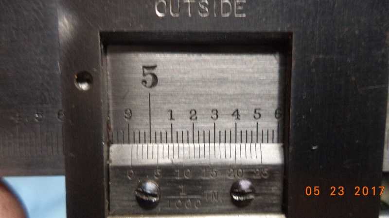 |
| 10.770” reading on a vernier caliper | 4.915“ reading on a vernier caliper |
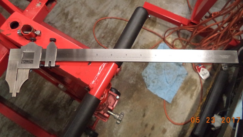
Telescoping Bore Gauge (snap gauge)
For measuring internal diameters / round holes (cylinders, bushings or other), snap gauges are used in the bore I.D.
The top end of the tool tightens the bottom arms in whatever length they are at the time.
Typical use is to loosen the shaft nut on top, close the arms, tighten the nut, insert the tool in the bore and loosen the nut.
Each arm snaps toward opposing sides in the bore (hence the slang 'snap gauge').
The arms are rounded on the ends and they will self center in the bore.
- The measurement is found by forward and backward movement in the bore with the gauge loose and with a slight drag.
- When you feel you are at the correct distance, (pulling straight in the bore with a slight drag on the tool), tighten the nut to keep that arm length.
- Before removing the tool from the bore, continue the movements to make sure you still have the same drag as you did before tightening the tool.
Then remove the gauge tool from the bore. - Next, use a caliper to measure the length of the gauge arms to find the internal diameter reading.
- Take several measurements instead of just one and at different points around the bore to check for equal roundness.
It takes practice and patience to get used to using this tool.
One measurement is usually not enough to say that you have a good reading from it.
Lots of factors are involved in getting the correct measurement with it also.
- Snap gauges are notorious for closing in (slightly) when the nut is tightened. This will give you a bad reading.
You should feel a slight drag in the bore with the arms loose and the same when tightened.
Continue with the forward and back motion until you feel like the tool is perpendicular to the bore (with a slight drag).
Then tighten the nut and double check that you still have drag on the tool BEFORE removing it from the bore. - It's also easy to turn the tool sideways (even slightly) and feel drag.
Then while double checking the distance when tightened, you get even more drag.
Since a sideways measurement is longer than a straight thru measurement, this will give you a bad reading. - Evo cylinders will naturally not be perfectly (a few thousandths variance in circumference).
To measure cylinder bore, the heads have to be off which releases the torque on the cylinder and distorts the bore.
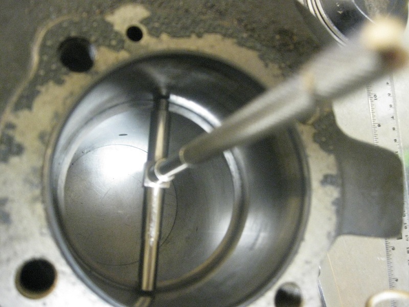 | 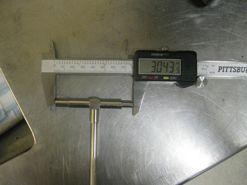 |
| Telescoping bore gauge and caliper for measuring cylinder I/D. 5) | |
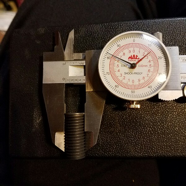
 | 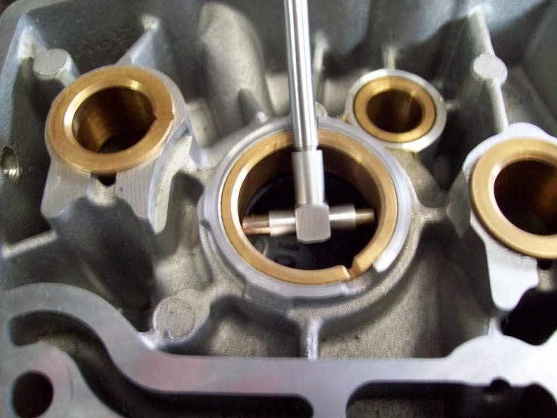 | 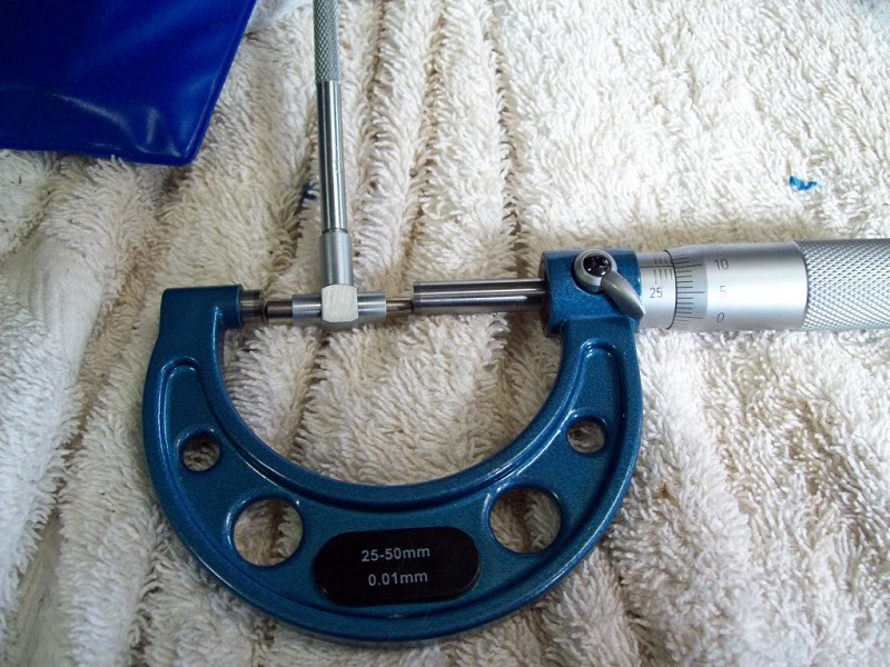 |
| Telescoping bore gauge and caliper for measuring cam bushinhgs. 6) | ||
Dial Indicators
(From time to time, you can spot check dial indicator accuracy with a feeler gauge). 7)
Dial Depth Gauge
Application
- This gauge is typically used to check piston height off the deck (piston at TDC and the gauge dropped from the deck). For this application, you'll need one that is accurate to the specs your engine / build requires.
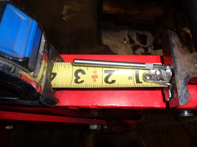
- It can also be used (with dual plug heads) to set true TDC when checking or creating timing marks on the flywheel. For this application, your only using the increments as a guide to which direction the piston is traveling. If your planning on this being a 'one use' tool, it might be better to opt for a cheap one. The probe needs to be about 3” long from the base out though.
Purchasing
- Research for the application needed can save you some time and a lot of money when buying a dial depth gauge. They can be expensive when buying new. Although, some nice used ones will show up on Ebay or other online auctions or stores periodically. You can get them with a fixed single probe end or removable various length ones, increments of .001“ or .0001” or metric versions, different base dimensions / lengths, various throw lengths (total measuring distance) and other variations. Just make sure it is what you think it is or need it to be.
| For versatility, it's nice to have removable probe ends of various lengths. Verify the total throw needed. 8) | Check the dims on your intended work area before purchasing your gauge to verify the probe end is the correct length on the gauge. 9) |
 |  |
Using
- Set the gauge on a clean machined surface or mirror, hold it firmly, loosen the faceplate thumbscrew, turn the faceplate gradients to read '0' and tighten the faceplate thumbscrew. At this point, all measurements will be taken from a 'known base-point' which you just established (0). Place the base on a clean flat surface with the probe hanging off that surface in the middle towards the target. Target is measured as it's distance away from the base as the probe is lowered.