Table of Contents

IH: Carburetor, Intake Manifold & Exhaust - Sub-01Q
Rebuilding the Keihin Butterfly Carb
See also in the Sportsterpedia.
Disassembly
- Removing the carb from the bike should be straight forward. First thing when it is out is to check the pilot screw setting. 1)
Turn it all the way in until gently seated counting the number of 1/4 turns; then write this number down; then reset it.
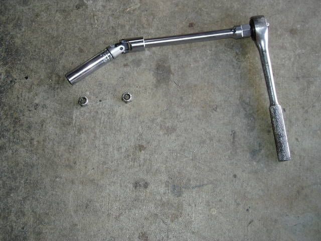
This rig works well to get the carb off to fit the heat block (if applicable) without having to take off the horn and ignition switch brackets.
1/2“ deep socket, 3/8” drive, universal joint and 6“ extension.
 2)
2)
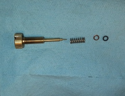
- Pilot screw:
- Remove the pilot screw and clean the parts and the passage.
- The passage contains in this sequence: (pilot screw, spring, washer, O-ring).
- These are very small parts, especially the washer and O-ring. Usually the spring will easily fall out.
- The technique for removing the washer and O-ring is usually to use a pipe cleaner:
Stick it in the hole, twist it around, remove it - you should see the washer and O-ring on the end of the pipe cleaner.
Remember that the purpose of the washer is to protect the O-ring from the spring and you will always get them back in in the correct sequence. - Note: Some carbs, notably 1966 to 1978 Sportster carbs, do not have the O-ring and washer in the pilot screw passage.
- Float bowl:
- Remove the Four screws and washers holding the bowl on the carb body.
- Removing the float bowl will also allow you to remove the accelerator pump rod and boot and access to the jets.
Be careful not to damage the accel pump nozzle and overflow pipe which are built into the bowl. - Remove the screw that holds the float pin, pin and float.
- Slip the float valve off the tab holding it on the float.
Take care not to damage the rubber needle portion of the fuel valve.
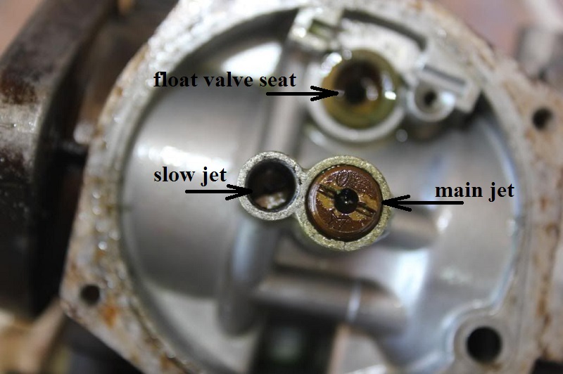
- Jets:
- The jets are made of brass, a soft metal that is easily damaged.
Use an exact correct size screwdriver to keep from damaging the slot.
You can grind a medium flat blade screwdriver down to exact size on a bench grinder to access the slow jet. - Make a list of all of the jets and passages for your carb using the carb manual or the FM for the bike.
Then ensure that you can blow either compressed air or carb cleaner thru each one. - Slow jet: Remove the black plug out of the tube above the slow jet (L76 only carb doesn't have this) and unscrew the jet.
- Main jet: Unscrew the main jet and tilt the carb body to allow the main nozzle to slide out of the main tube.
- Accelerator pump:
- The accel pump can be removed without taking off the float bowl if desired.
- Remove the three screws and washers on the bottom of the bowl to loosen the pump body from the carb body and carefully slide the assembly off.
- Note the sequence and orientation of the parts.
- Remove the spring, diaphragm, O-rings and check ball (if applicable) taking care to catch the small parts in your hand.
- If you drop the pump housing, inspect the mating surface for dings that would prevent it from sealing out a gas leak upon installation.
Cleaning
- Make sure to take everything apart, jets, needle, accel pump, all rubber components especially.
- Examine all parts for excessive wear, damage, distortion, etc.
- Cleaning solutions/sprays vary based upon your location, needs, budget, preferences and quality.
Dismantle the carb down to the body before soaking. You will be surprised at all the dirt in the bottom of the soaking container.
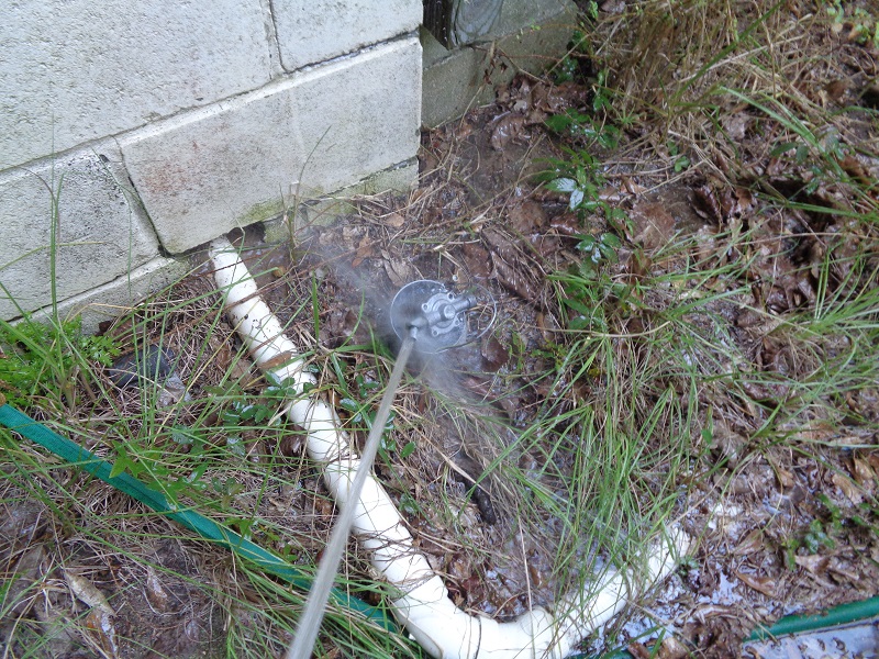
Here are some helpful ideas:- An overnight soak in a solution of Pinesol and water followed up with a good brush down with a toothbrush then rinse and air dry. 3)
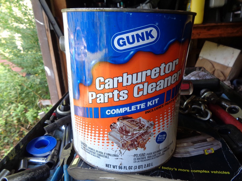
See also Soaking parts in the REF section of the Sportsterpedia. - A 20 minute to up to a few days soak in a gallon of Gunk (or other) Carburetor Cleaner that has a basket inside for small parts and lowers in the can with a handle, rinse, air dry, use.
- Soak it in mineral spirits for a few days. 4)
- You can use acrylic paint thinners for cleaning up carb parts. It melts the fuel varnish right off. 5)
- An aerosol spray carb cleaner will also work but may not loosen all of the build up in the jets or orifices in the carb body if they're not directly sprayed through.
- Blow out all holes, jets and orifices thoroughly with compressed air after cleaning.
Reverse air flow through each passage to ensure removal of all dirt particles. - Blow out the accelerator pump check valves (1 inside the accelerator pump nozzle and 1 inside the accelerator pump housing).
You can shake the fuel bowl when it is off the carb. The nozzle check valve and / or check ball should rattle in the bowl housing.
If you cant hear it, it's stuck and the accelerator pump will not work. 6)- The nozzle check valve is inside the brass spray nozzle. It should be reverse blown due to the nature of it's function.
Blowing from the pump nozzle will just shut down flow when the valve closes on it's seat.
It is weighted and looks very similar to the float valve except the tapered end is metal.
It should move up off it's seat and then lower back down on the seat. - The check ball is either inside a passage cast into the carb bowl (from the bowl to the pump) or in the pump housing itself.
When this passage gets gummed up, the check ball usually gets stuck closed, hence why the pump does not work.
The check ball is rarely considered when rebuilding a carb.
It's also very hard to clean. The only way is to blast the passage with carb cleaner and compressed air over and over until it works.
Sometimes soaking alone does nothing for freeing up the check ball without blasting it with carb cleaner and air or brake cleaner.
- The FSM says to not use wires or drills to clean small holes as this could cause burrs or change the hole sizes.
However, done carefully (and only if needed) with smaller wire than the intended hole to clean, this has been an affective way of removing caked varnish.
Use at your own risk.
A gallon of carburetor cleaner is very useful in cleaning parts.
It is especially useful for soaking stuck gaskets between parts and loosen the joint between them for dis-assembly.
Depending on how old or how 'stuck' the parts are, soaking for a couple hours may help to separate the old gasket in between.
Make sure to remove any rubber or plastic parts before soaking. Also check the label for safety precautions.
Parts that have been sitting for years may have to be soaked for about 24 hours or even days.
| Carburetor Cleaner 7) | |
 |  |
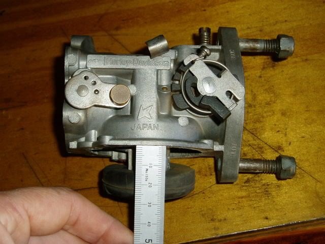
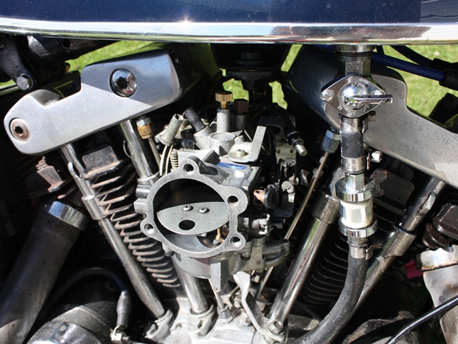
Carb Stand
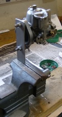
Making a carb stand is not very difficult especially if made from aluminum flat stock.
It makes float settings as well as detail cleaning easier.
In the pic below, the carb is mounted to the top of the stand but you can also mount it lower on the stand to make it easier to flip over.
- You can put the carb in a vice to remove the screws, and for much of the following work.
Wrap in a shop towel; close the vice gently taking extra care with the choke and throttle linkages.
The vice is a needed extra pair of hands. - It can be very confusing trying to decide which way to bend the tang if it is not correct.
If the fuel level is low,Is the float high or low?, Do you need to bend the tang up or down? etc.
On the bench the carb is usually upside down, adding to the confusion. You should sort all this out before making an adjustments.
This setup works better than putting the carb (pre-CV) directly into the vice.
The carb is set upright as 'in use' making adjustments more straight forward.
 8)
8)  9)
9)
Rebuild Kit
You can purchase individual parts or a rebuild kit.
The kits will not have needles, jets or the spring, washer & o-ring for the Idle Mixture Screw.
It's best to get the rebuild kit with Viton rubber because it doesn't swell due to modern gas.
The HD rebuild kit is part# 27006-92T.
V-Twin Viton Rebuild Kit: #35-9176.
V-Twin Rebuild Kit: 35-9172.
J&P Cycles Rebuild Kit: #4000050.
Guenuine James Rebuild Kit: JGI-27006-76.
- Carb-to-Manifold Seal
- Carb-to-Air Cleaner Gasket
- Float Bowl Gasket/O-ring
- New Float Needle
- New Accelerator Pump Diaphragm & Spring
- Some Misc Parts/Seals
If you get a kit, do not discard any of your original parts especially the needle valve. The ones in the kits have a very bad reputation. 10)
Assembling the carburetor is basically the reverse order of disassembly with the exception of setting the float level. See below.
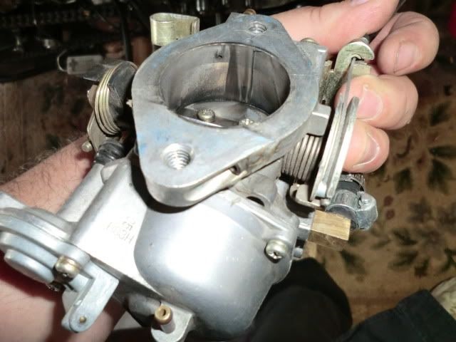
Float Valve:
The 3-sided valve (left below) 'may' sit cock-eyed in the seat sometimes and cause a leak. 11) The four sided (right below) valve is 'supposed' to be an improved design.
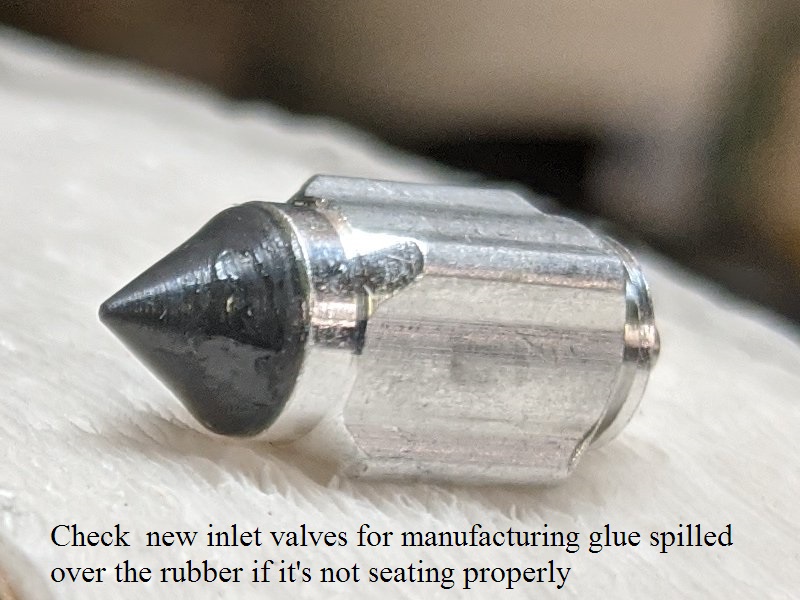
Also check new float valves for manufacturing errors. The glue holding the rubber on has been known to have spilled onto the rubber causing a bad seat.
 12)
12)  13)
13)
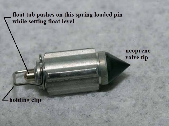
The float needle should just kiss the seat with no extra pressure. Aftermarket float valves have a spring loaded pin under the float tab. So when the valve tip closes onto the seat, you can still push the valve down further. The valve should 'just' close when measuring the float level. Pushing further in from there will not close the valve any further. But it will cause you to set the float level wrong. The valve should be a light seat when measuring. Some aftermarket float needles with the spring loaded pin also have a defective neoprene tip on the other end (which does not seal even when set right). 14) Since the tip on the needle on aftermarket ones don't work well, some would use the old original one (solid pin) to get a better measurement. 15) Beats assembling the carb only to have it sit there and flood with gas. Also make sure you have the float valve for the correct type of Keihin carb. The aftermarket valves are a little taller.
 16)
16)  17)
17)
Bowl Gasket:
Float Level Adjustment.
Check the float level using the specs in the FSM for setting the float level.
And check it every time you dismantle the carb (as the last thing before putting it back together).
After checking the float level, then carefully put it back together.
Replace the screws:
It's best to replace the original Phillips screws for the bowl with stainless steel socket head screws.
The measurements in the FSM are a reference point that will keep the OEM float within a fully open and fully closed position.
Using aftermarket parts, you may have to adjust some.
With carb in bike, you can put a small catch tin under it and turn on the gas and move the float until the flow of gas actually stops.
(with no smoking or flames of course)
Procedure:
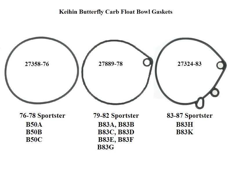
76-78 Sportster carbs
Two positions of the float valve must be set; The valve fully closed and The valve fully open.
Setting the closed position lower will tend to make the carb act lean at low speed.
Setting it higher can cause rich running, flooding and dribbles out the overflow line.
Equally important is to set the wide open float setting by bending the other metal tag on the float by the pivot.
This makes sure the float needle fully opens at full throttle openings and allows full fuel flow without starvation.
It also stops the float hitting the bottom of the float bowl and possibly getting damaged.
If the gas level is too far off, you will not be able to tune the carb. 18)
- Fully closed measurement: Tip the carb upside down so the float assembly is facing up.
Measure from outside surface of the float to flat mounting surface of the carb body casting.
Measurement: 9/16” to 5/8” (14mm-16mm). 19) - Fully open measurement: Next turn the carb over (right side up).
Measure from the same surfaces as above (outside surface of the float to flat mounting surface of the carb body casting).
Measurement: 1-3/32“-1-3/16” (28mm-30mm). 20)
The MoCo sold a float level gauge (94752-77) for measuring or you can use a ruler or caliper.
The actual adjustments are made by carefully bending the two tabs of the metal clip on the float assembly until these two dimensions are achieved.
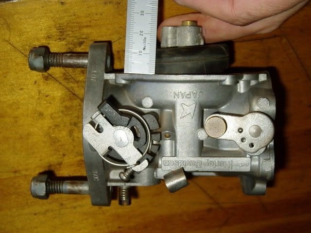
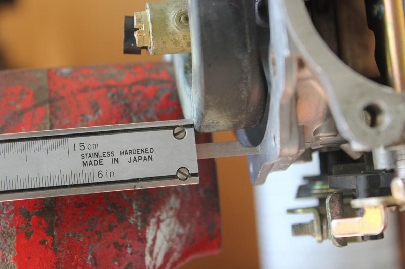
79-87 Sportster carbs
There is only one measurement to set with these.
Turn the carb body sideways as shown below.
The valve should be fully closed with a measurement of .63“-.67” (16mm-17mm) from the top of the float to the bowl mounting surface. 23)
Servicing the Carb
See also Keihin Carb Upgrades - Butterfly and CV Types in the REF section of the Sportsterpedia.
Carb body and float bowl
Check the mounting flanges / mating surfaces for war-page. Set the flange on a flat surface such as a plate of glass or window. 25)
Use a feeler gauge to check for war-page. File or sand flat if necessary.
If warp-age exists, it may leak air and drive you nuts trying to find the source of the leak.
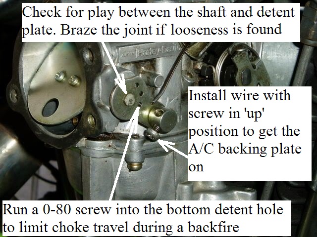
Choke Shaft
- On 76-78 carbs, check where the choke detent plate attaches to the shaft can get loose and sloppy. 26)
This joint can be brazed to tighten it back up and get better choke action. - During a backfire, the choke can slap all the way shut. 27)
Then you kick it 5,000 times wondering what's wrong, you've flooded it, the plug's get wet and you're pushing it.
You can put a 0-80 screw into the lower hole in the detent plate to keep the choke plate from slamming shut and causing problems starting.
These holes are for a ball detent on the back side of the detent plate.
By installing a little 0-80 screw right there, when the bike backfires and they always do, the choke doesn't fully close and will save you a lot of grief. - When hooking up the choke cable, if you put the mounting screw down, you can't get the air filter on. 28)
You need to tighten it with the screw pointing up, at least the after-market air filters.
That chrome back plate, when it slips on, there's not enough clearance down there if the screw points down.
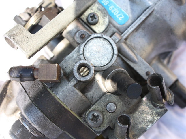
Low speed mixture screw
A service bulletin was issued in Dec. of 1976 regarding a possible air leak at the low speed mixture hole. 30)
To seal the hole and keep the mixture screw in place, it was suggested to remove the screw, install a gasket (27355-76) over it and re-install it.
Enlarge the hole in the gasket to permit a snug fit on the screw and install it between the spring and the carb body.
When resetting the screw, turn it in until lightly seated, then back it out 7/8 turn.
(this was a change from the original suggestion for FL and FX models in December, 1975 of 1-1/2 turns) 31)
The change was made after the Sportster began using the Keihin carburetor so this would've affected the L76 and E77 carbs.
Idle Transfer Ports
These are four holes (as viewed from the upper inside of the venture from the engine side).
- Check that the ports are not gunked up and are free of obstructions.
- Check that the Welch plug over the top of them isn't leaking.
It's good to remove any old sealer over the Welch plug and install some fresh. Read about Welch Plugs below. - If you've dunked the carb in carb cleaner, any sealant that was around the Welch plug would now be compromised and resealing is a must.
Jets

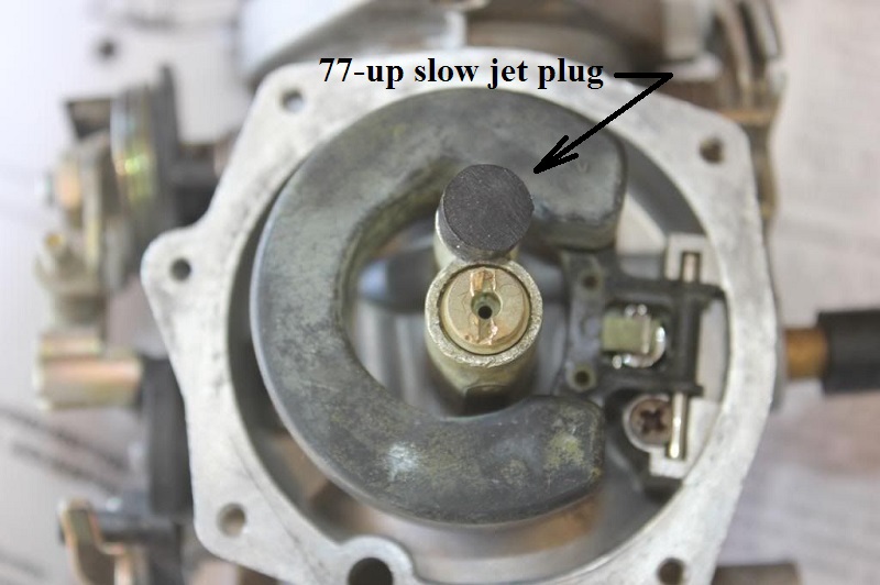
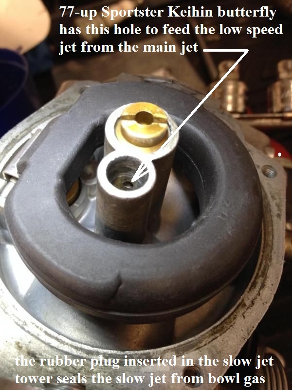
77 and up (disregard for the L76 Sportster carb):
The black rubber plug is installed in 77-up Sportster Keihin butterfly carbs over the slow jet.
There is a drilled passage between the slow jet and main jet wells and that's how the slow jet is fed.
Blow this hole out with compressed air and make sure it is unobstructed or it'll cause a lean condition.
Check to make sure current or replacement plugs are not too long or that will also cause a lean condition.
Correct it by either cutting the end to .20” (5mm) long from shoulder to tip or replacing the plug (27385-76). 33)
Check to see that the hole does exist between the wells for verification that you do need the rubber plug installed.
Read more about the function of the rubber plug (or bung) Here in the Sportsterpedia.
All year Keihin jet locations:
 36)
36)
Float disassembly / assembly
The general appearance of the inside of the carb is not necessarily a good indication of its condition.
It can look spotless and have clogged jets, or look cruddy and have clear jets.
It's good to clean each individual part rather than soak or boil the whole carb in carb cleaner.
But either way is good. Do not allow any solvents to contact any rubber parts (tip of needle, O-ring seal for bowl).
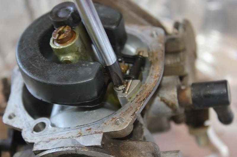
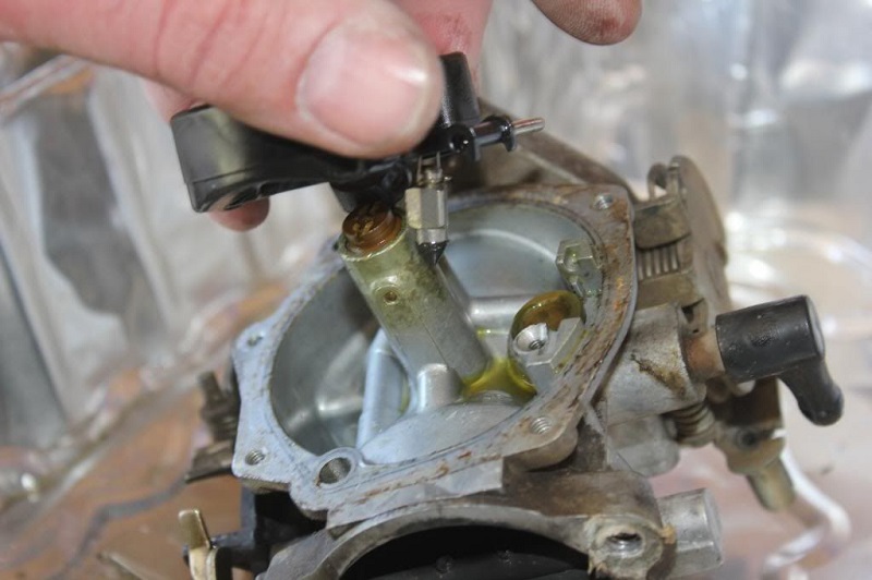
Guide the bowl so to not bend or damage the overflow tube when removing or installing it.
 39)
39)  40)
40)  41)
41)
Accelerator pump
- Clean and inspect the diaphragm for pinholes, cracks, rips, deformation, gunked up rust or varnish deposits and etc.
Replace the diaphragm if necessary.
When installing the diaphragm, you can add a bit of silicone grease or rubber grease on the lip around the outside of the diaphragm. 42)
It helps to make sure it slips right in the groove and stays there.
The diaphragm may fit snuggly in some carburetors and loose in others despite the diaphragm being the identical size. 43)
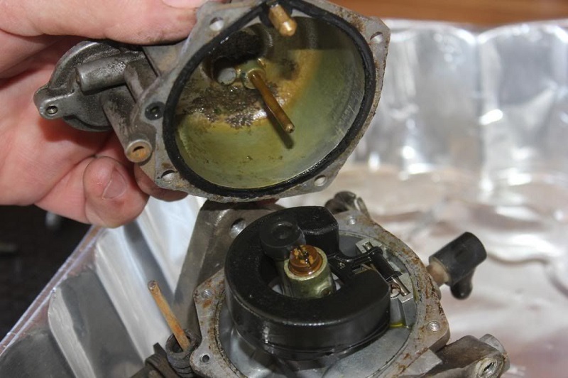
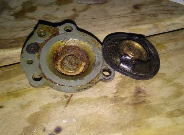
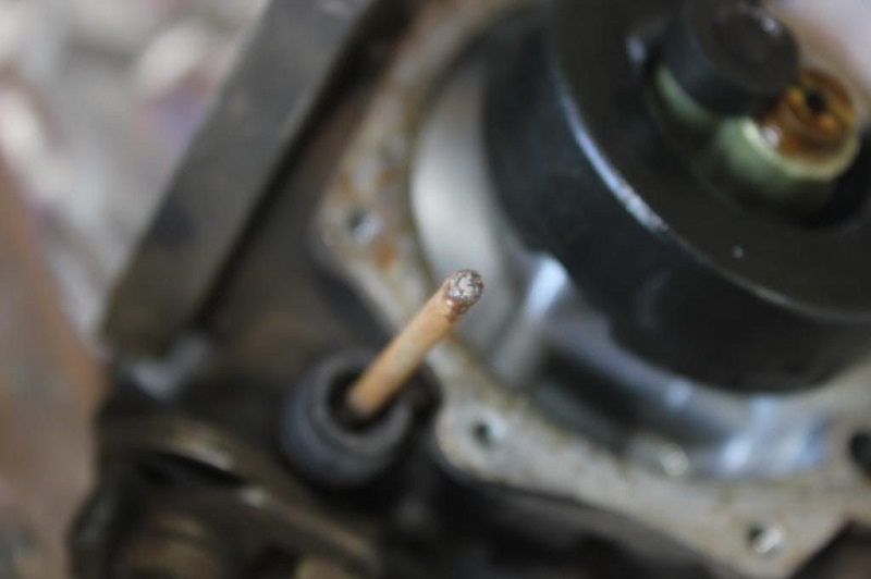
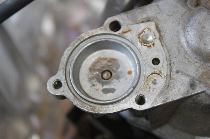
You can place a tiny amount of silicone lube (spark plug boot lube) in the groove to hold the diaphragm in place during assembly. - Inspect the accelerator pump rod for bending or rust.
If not maintained, you may dismantle the carb to find small pile of rust in the accel pump bowl.
The rod can rust and rust particles can brush off of it and accumulate in the bowl.
You can spray the rod with a silicone lube to help cut down on rust accumulation. - Inspect the rubber boot for cracks / tears.
Any dirt that gets past the boot into the accelerator pump passage should be blown out from the side opposite of the nozzle.
(or check valve will close, making cleaning impossible) - Condensation gets inside and causes rust to form. 44)
The air flow will have a cooling effect on the carb and with humid summers, moisture would form and collect under the rubber seal.
This would be seen more from short rides in town. - It's also been noted that ethanol in the fuel sucks up water from the atmosphere and corrodes the fuel system. 45)
Generally gravitates to low points in the system - like the acc pump bowl etc.
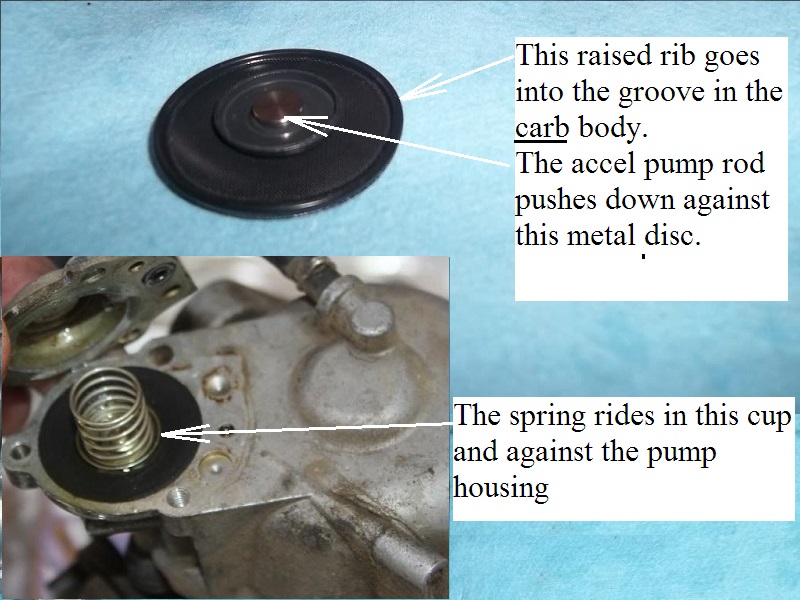
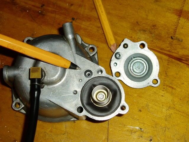
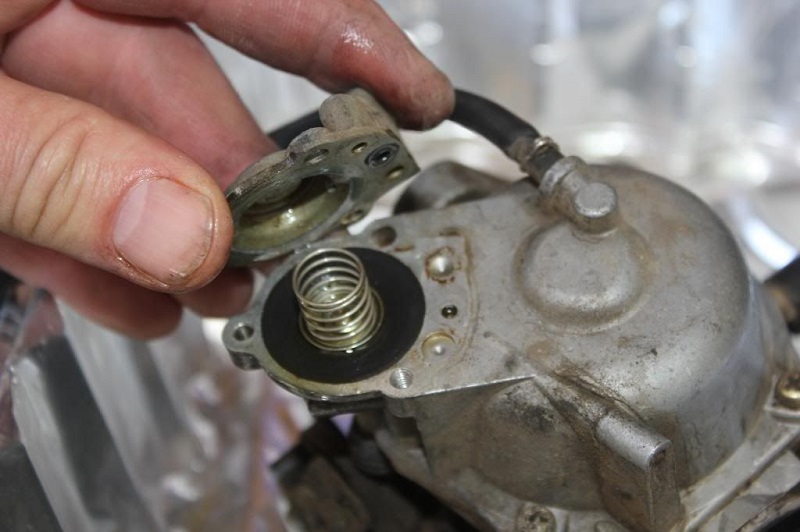
While installing the accelerator pump, the diaphragm goes on first, then spring, then cover.
The spring sits between the bottom of the diaphragm and the housing. It pushes the diaphragm back up after the rod pushes it down.
There are two short screws and one long one that hold the pump housing to the float bowl. 48)
76-78 OEM accel pumps have 2 O-rings
Make sure to use both and that they are squarely in place and in good condition.
Else, gas will leak out there instead of getting squirted into your engine.
One O-ring goes in the carb body pocket and the other one goes in the accel pump pocket.
 50)
50)
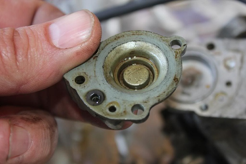
79-up OEM accel pumps have 1 O-ring
Again, make sure the O-ring is squarely in place and not squished to allow a leak or to stop up the passage.
Also check to see if your carb and pump housing has been upgraded to a dual chamber pump that would require two O-rings.
In that case, you'll notice 2 thru holes from the pump to the carb body as well as in the pump housing.
Below is an accelerator pump on 1981-Early 1982 27469-81A (B83F). There is only 1 thru hole from the pump to carb body.
The one hole acts as both a fuel filler and accelerator discharge by way of a check ball in the bowl to pump passage.
 51)
51)  52)
52)  53)
53)
Testing the Accelerator Pump Off the Carb
It's good to test the accelerator pump function before installing the carb on the bike. Else, you'll just have to take it back off if it doesn't work.
- Take the bowl the pump rod off the carb with the pump housing still installed.
Put some fuel in the bowl (you can also use water as it is fire safe and nonflammable) and put the pump rod in it's hole in the bowl. 54)
Push the pump rod with your finger and see if you get spray out of the brass nozzle.
You will see it flow in a stream (not intermittent) when the pump is working. - If the pump doesn't spray a stream;
- Check the diaphragm for damage / proper seating.
- Check that the spring is installed underneath the diaphragm.
- If the pump does spray but doesn't with the bowl installed;
- Inspect the accelerator pump linkage for adjustment or mechanical issues.
- Make sure you can shake the bowl and / or the accelerator pump housing and hear the check assemblies move.
If not, see Cleaning above to get it loose.- The nozzle check valve and/or check ball should rattle in the bowl housing.
- There is a check for both the inlet and outlet of the accelerator pump system.
- If you cant hear it, it's stuck and the accelerator pump will not work. 55)
Accelerator Pump Rod Length
 The accelerator pump rod length was mentioned in a service bulletin in November of 1975. 56)
Apparently, some early carbs were assembled with the accel pump rod being too long, eliminating any free play and causing an over-rich condition.
Since only 10% of the early production carbs may have been affected, a spacer was made available to fit over the pump lever.
This spacer would fit over the pump lever to keep it away from the throttle lever thus raising the rod to produce the necessary free play. The spacer had two different spacing thicknesses on opposite sides to flip as needed to shim.
This shouldn't have affected the Sportster carb as the first production was in L76 but may be found in older Keihin BT carbs.
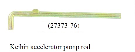
The original pump rod is part# (27310-76).
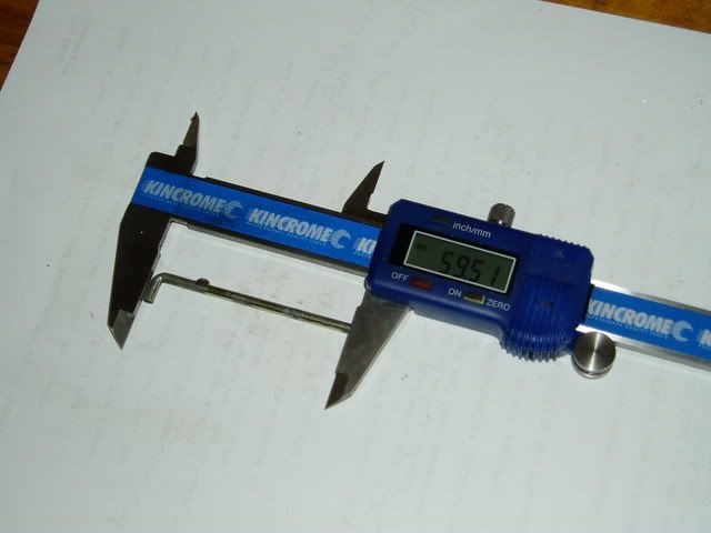
The updated pump rod for is part# (27373-76), length 2.34“ (59.5mm). 57) 58)
An alternative to the spacer or the updated pump rod was to shorten the longer rod (if equipped).
Remove the pump housing, spring and diaphragm.
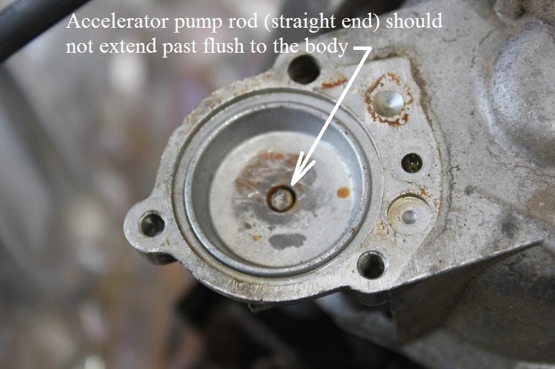
With the idle adjusting screw backed off, the rod should extend into the pump well from the bottom surface no more than .040”.
If it projects too far, disassemble the rod and grind off the required amount from the straight end.
Joe Minton wrote a popular magazine article in which he describes this as well. 59) 60)
According to the article, filing the end off the accelerator pump rod is another important modification to aid smooth idle.
This stops it resting on the pump diaphragm at idle and jiggling it up and down, pumping minute amounts of fuel into the carb throat.
(which dribbles along the bottom of the throat and is not properly mixed with air so it makes the bike run rough}
The actual length is hard to measure because the end is not square. But it still sticks out beyond the carb body at idle and pushes on the diaphragm.
The carb 'trouble shooting chart' in the manual lists “accelerator pump pushrod incorrectly adjusted” as one cause of rough idle. 61)
But it does not offer any information on how to adjust it.
The TSB mentioned above sets the depth at .040” so we have that plus the measurement in the parts catalogs.
Make sure to check this length on used carbs and replacement rods also.
You can use a file to cut down any extra length off the straight end of the pump rod if sticks out past the end of the hole it sits in at idle.
While assembling the pump, check that you can grab the pump rod with a pair of long nose pliers and feel that it has some up and down shake when in the idle position.
You'd think this might cause a slight delay when cranking the throttle from idle, while the slack is taken up.
But it has been done and on the road with no detectable delay. The gap is tiny.
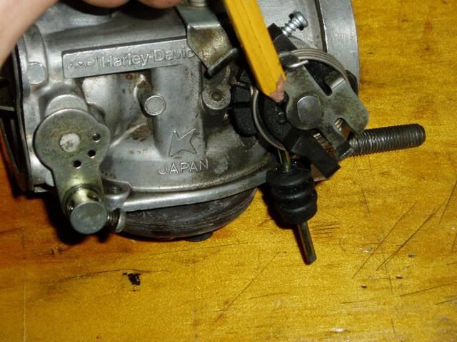
In the second pic below where the right-angle end of the accelerator pump pushrod fits, the bottom straight end is the end to file down very slightly.
Note:
If the accelerator pump rod is too long, it will be spurting fuel at steady throttle. 62) 63)
Check by removing the air cleaner cover and see if any fuel is leaking or spitting from the accel pump nozzle.
If it is spitting, you will be able to see it doing so. Correct by removing the rod and shortening it to 2.34“ (59.5mm).
Do not shorten it under any other circumstances. Filing it too short will affect pump action and cause poor acceleration. 64)
| Measure the rod length. 65) | File bottom straight end. 66) | Pump rod flush to body with throttle closed. 67) |
 |  |  |
Add'l Info & Pics -
Accelerator Nozzle, Check Valve, Float Seat - http://xlforum.net/forums/showthread.php?t=1624208
Accelerator Nozzle & Check Valve - http://xlforum.net/forums/showthread.php?t=1775068
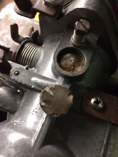
Idle Mixture Screw
If you still have the factory plug over the mixture screw, you'll need to drill it out to access the screw.
To keep from drilling too far into the plug, you can use some electrical tape around the drill bit to mark the depth to drill.
Then pry the plug out using a pick or you could twist a small sheet metal screw into the hole to pull the plug out.
With the plug removed clean the area around the mixture screw so no metal fragments remain.
 68) Circled area is where you drill out the plug.
  69)
69)
Some have cut the idle mixture screw tower down for easier access to the screw when adjusting.
Be sure to stuff some material (pantyhose etc.) in the hole beforehand and blow out the hole and passages with compressed air afterwards.
You can also just buy a longer thumbscrew. See more on the EZjust screw below.

EZ-Just Mixture Screws
 70)
70)
The EZ-Just mixture screw (for L76-87 models) 71) ) can be purchased with an extended screw head for hand tuning.
You can buy packing from CVP also in case yours has been damaged or is not functioning properly.
But, check your local regulations before changing this out to an aftermarket part.
You can also find, buy or barter for used parts.
(“Please note: it is a violation of federal law to tamper with or disable any emission or noise control device. That is your PSA for the day”). 72)
The EZ-Just mixture screw must be threaded in completely (lightly seated) prior to backing out and making final adjustments.
Typically between 10-12 full rotations of the screw to seat.
If you can see more than 1-2 threads after seating the screw, the screw is not screwed in completely.
This could result in the screw falling out during operation.
If you have trouble fully threading the EZ-Just, this indicates the inside threads of the carburetor need cleaning or have a damaged thread inside.
Working the screw in/out with light machine oil (3-In-1 or other) will often help work past any carbon build up inside the carburetor threads.
The packing for the EZ-Just is the same as OEM: (screw→ spring→ washer→ O-ring).

Welch plug
- Inspection:
- A close inspection around the walls of a welch plug can reveal possible leaks.
- Removal: 76)
- Whenever a welsh plug is removed, a new one should be installed in it's place, especially since a large part of the time, removal of one means destroying or deforming it.77)
- Drill an 1/8” hole thru it (just deep enough to break thru to the other side) off center and pry it out with a small punch. Be careful not to drill too deep which could destroy the nozzle assembly or casting. While prying it out, be careful not to damage the casting counter-bore edges around the plug.
- You can also drill a small hole in it and use a small tap just big enough to start in the hole. 78)
Thread the tap in the hole.
When it gets to the bottom of the passage, it will force the valve out with out damaging the bottom of carb passage.
Make sure to clean all the chips out to keep from plugging up passages later.
-
- The plug should be seated with a flat end punch that is slightly smaller than the diameter of the plug. The plug should be flat and not concaved to assure a tight fit. If leakage is suspected due to a rough or damaged welch plug seat in the casting, apply a small amount of epoxy or suitable sealant to the edges after installing it.
Links to Welch plug sites:
Remove the old filler material to expose the plug. This is a L76-78 style carb.
As a precautionary measure to eliminate possible air leaks, apply an adhesive type sealer to the two welch plugs in the top of the carb. 81)
Apply a minimal amount only to the joints between the edges of the plugs and casting.
 82)
82)  83)
83) 84)
84)
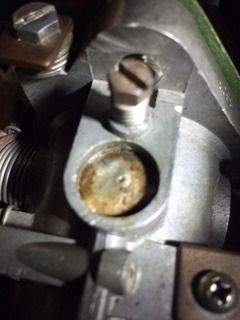
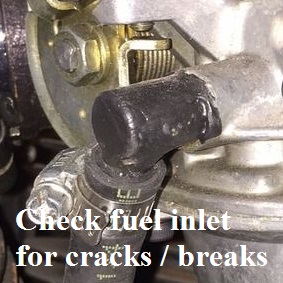
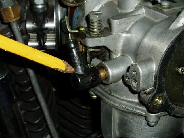
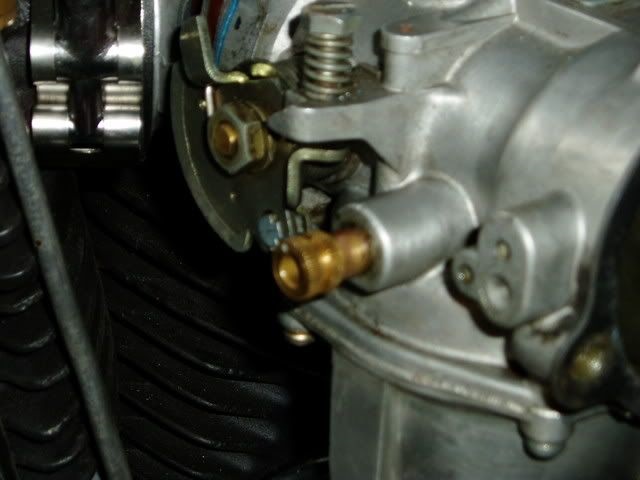
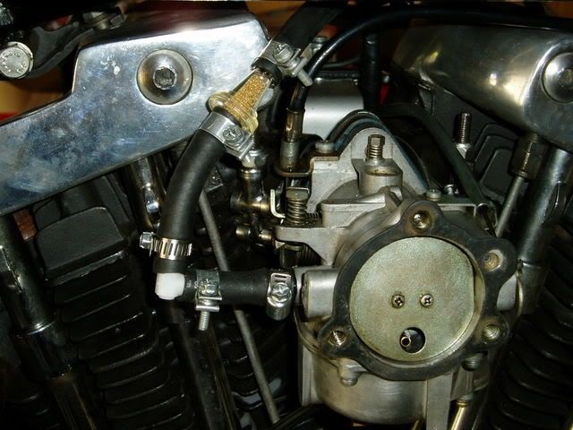
Fuel inlet fitting
Check the plastic fuel inlet for cracks or breaks.
Time will make the plastic brittle. You can be proactive and just replace it with a brass 90 elbow.
See Replacing the Plastic Fuel Inlet Fitting with a Brass 90 Degree Fitting in the Keihin carb upgrade article in the REF section of the Sportsterpedia.
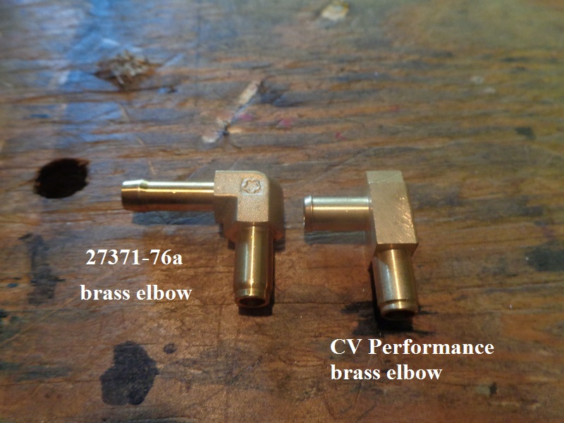
The brass replacement elbow part number (27371-76a).
The CVP brass elbow fits Harley CV40 carburetors 1988-2006 and Harley Keihin “butterfly” carburetors 1981-1989. 85)
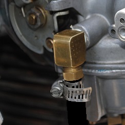
Or you can just break the plastic off the brass ferule with a pliers. 86)
Then file down the serrations underneath and plumb in some gas line to clamp straight onto it then connect to an elbow.
Broken flange repair
For a broken flange, you can try milling some slots in the flange and drill and tap the holes for screws.
You can use some JB Weld in there to insure a good seal.

Choke Rod / Cable
The old factory steel choke wire and the steel bracket works best.
When the bike backfires, it resists slapping the choke shut.
The cable type ones allow more flex at the bracket and subsequently the choke plate.
High Altitude Modification Kit
- Carburetor modification kits (including jet(s) and an accelerator pump stop screw) were made available for 1200cc, 1340cc and 1000cc models to provide leaner fuel mixtures when operating at elevations above 4000 feet sea level. 93)
- Normally, leaner fuel/air mixtures are required for proper engine operation as the elevation above sea level increases. The decreased jet sizes and accelerator pump modifications should be installed where there is evidence of a rich condition causing loss of smooth combustion, stumbling on acceleration or such other carburetor issues at high altitudes.
- High Altitude Kits:
- 1978 1/2 FLH-1200 (27094-78).
Consisted of a 160 main jet, 72 slow jet and a label for the downtube.
In addition to installing the parts on the carb, the FLH-1200 models required changing the position of the accelerator pump spring pre-load position.
The spring should go in the top (#1) position as opposed to the #3 (std) position on the pump lever. - FX/FXE/FXS-1200 (27095-78).
Consisted of an accelerator pump screw and a label for the downtube.
Install and adjust the accel pump stop screw to extend 1/8“ past hole in lever. - XLH/XLCH/XLCR-1000 (27096-79).
Consisted of a 160 main jet, an accelerator pump screw and a label for the downtube.
Install and adjust the accel pump stop screw to extend 1/8” past hole in lever. - FLH-80, 1340cc, (27093-78).
Consisted of a 155 main jet and a label for the downtube.
Note, any motorcycle modified for high altitude operation must be converted back to standard if operated at altitudes below 4000 feet.
An overly lean condition can cause engine damage.
Helpful Links
7)
photos by Hippysmack
23)
1979-1985 HD Sportster FSM pg 4-8
26)
, 27)
, 28)
, 48)
sportsterpaul's Keihin Rebuild Video https://www.youtube.com/watch?v=f_Ek37GEEN4&feature=youtu.be
29)
photo by Hopper of the XLFORUM, annotated by Hippysmack
32)
photo by billblack of the XLFORUM, cropped & annotated by Hippysmack https://www.xlforum.net/forum/sportster-motorcycle-forum/sportster-motorcycle-era-specific-and-model-specific/ironhead-sportster-motorcycle-talk-1957-1985/162826-which-keihin-do-i-have?highlight=keihin+bowl#post4770495
49)
photos cropped - annotated by Hippysmack
58)
1954-1977 HD Sportster Parts Catalog Supplement 99451-77A
67)
photo by sifty of the XLFORUM
69)
photo by popgadget of the XLFORUM, annotated by Hippysmack
72)
XLForum member - chrishajer
93)
HD Service Blletin #M-730 dated June 15, 1978
94)
Used by permission of SportsterPaul at the XLForum - https://www.xlforum.net/forum/sportster-motorcycle-forum/sportster-motorcycle-era-specific-and-model-specific/ironhead-sportster-motorcycle-talk-1957-1985/192176-keihin-butterfly-carb-rebuild-videos?t=2055701