Table of Contents

IH: Oiling & Lubrication - Sub-03A
77-85 Oil Pump - Individual Parts and Pics
See also 77-85 Oil Pump and Parts (app.) Dims
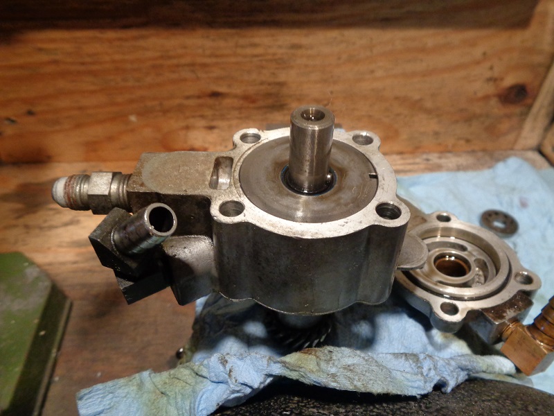
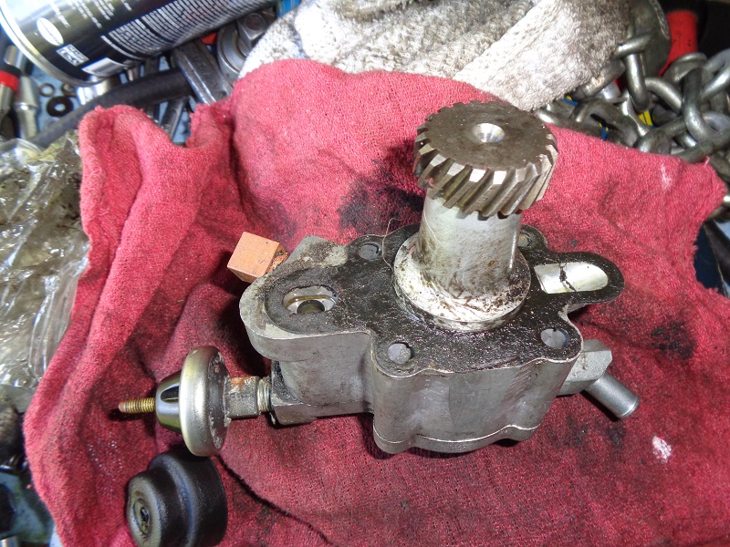
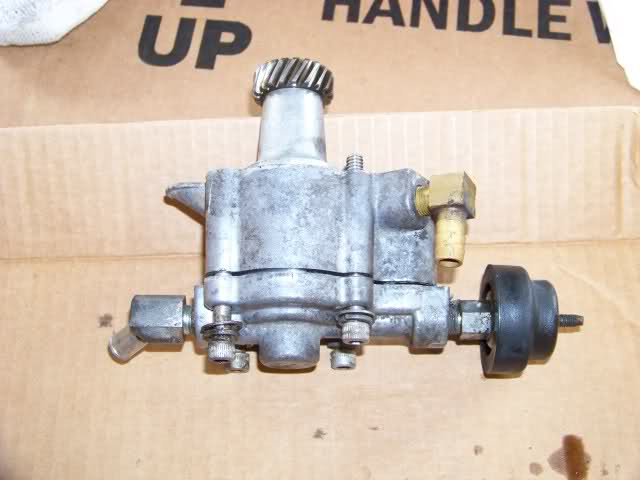
77-85 Oil Pump
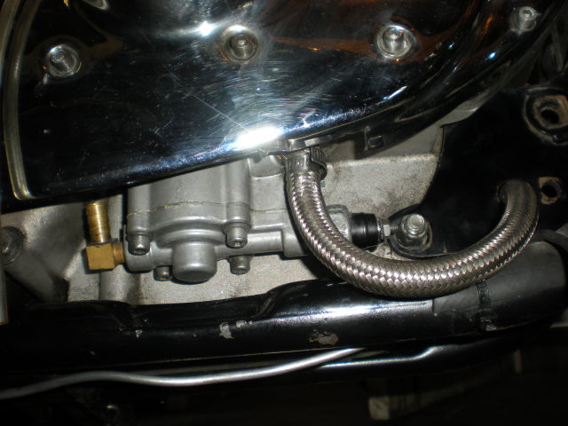 |
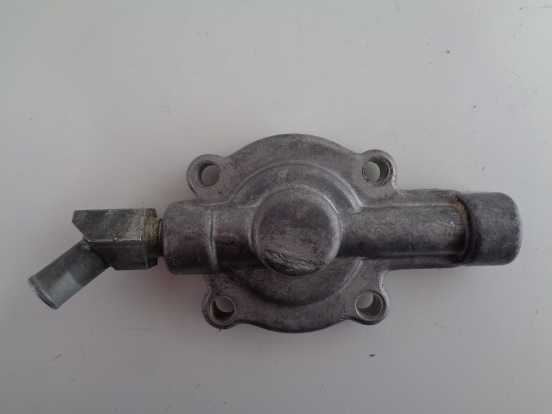
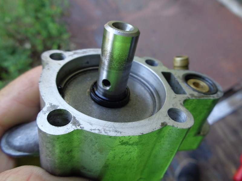
| Oil Pump on 83 XLX 1) |
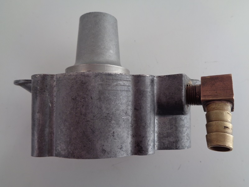
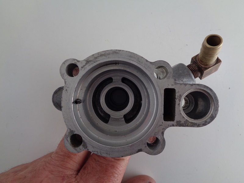
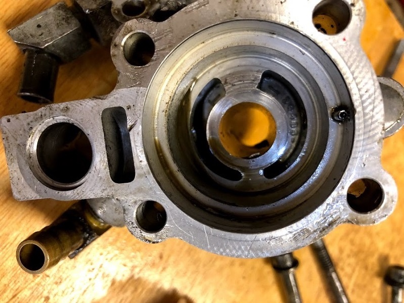
Oil Pump Body and Cover
E77:
Special “1600” oil pump stamped with an “O”:
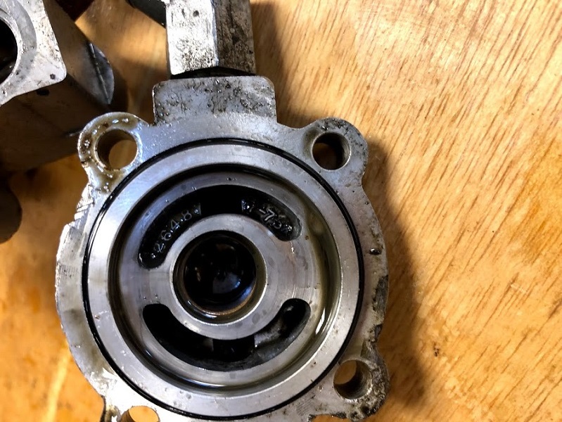
(26484-75) Oil pump body
(26486-75) Pump cover
Late 77-81:
(26484-75) Oil pump body
(26486-75) Pump cover
82-E83:
(26484-83) Oil pump body
(26486-83) Pump cover
L83-85:
(26484-75A) Oil pump body
(26486-75A) Pump cover
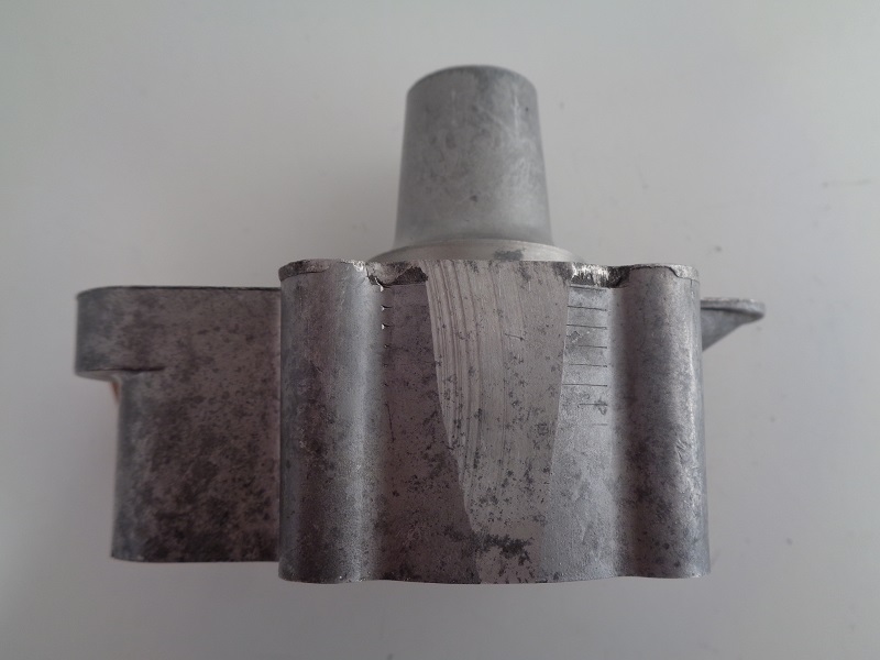
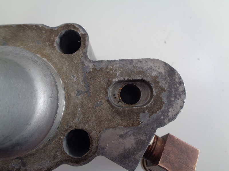
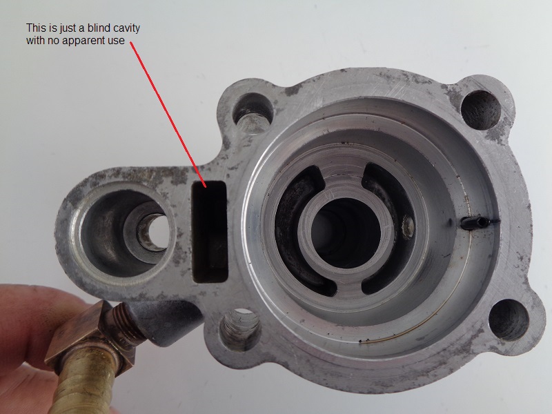
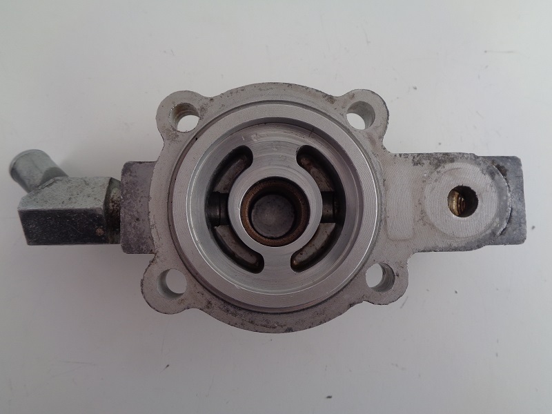
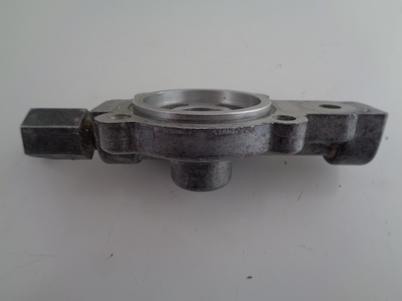
Oil Pump Body
77-E83
 |  |
 |  |
 |  |  |
L83-85
| Late 83-85 pump body 2) |
 |
Oil Pump Cover
77-E83
 |  |  |
 |  |  |
L83-85
| Late 83-85 pumpcover 3) |
 |
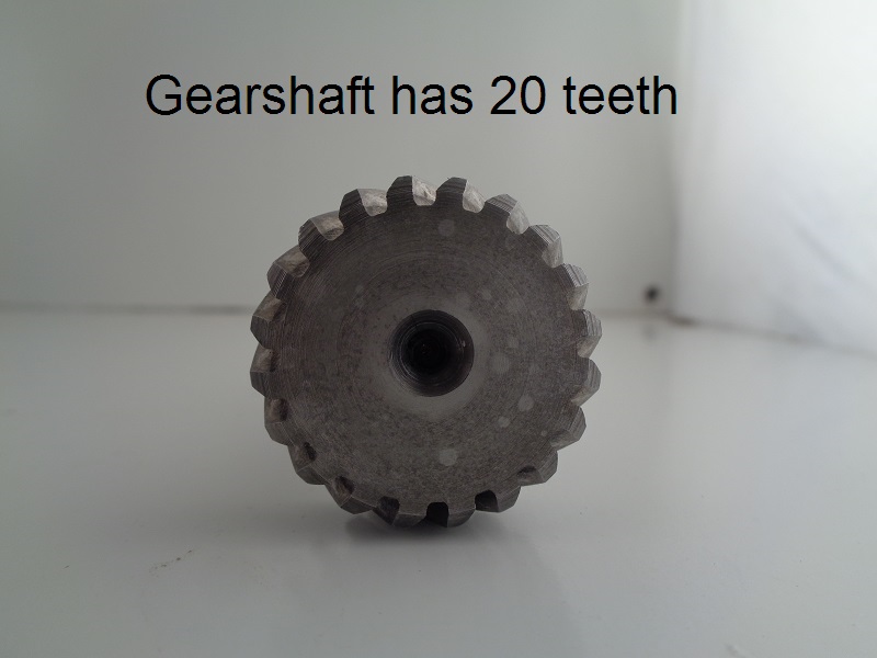
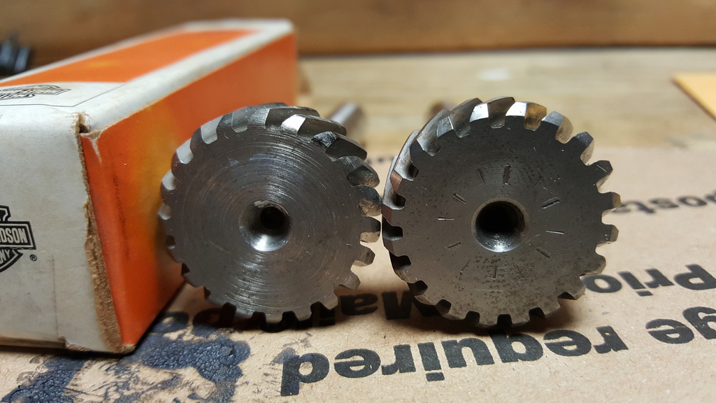
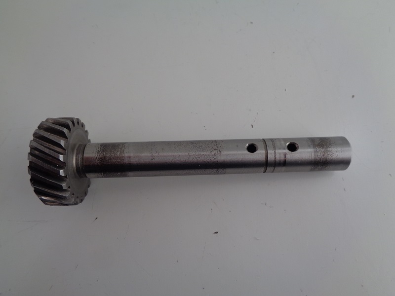
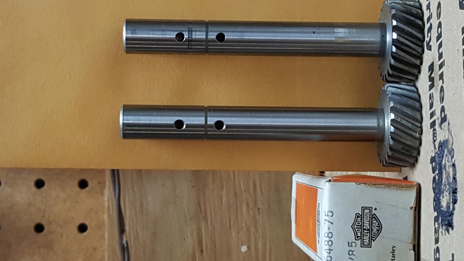
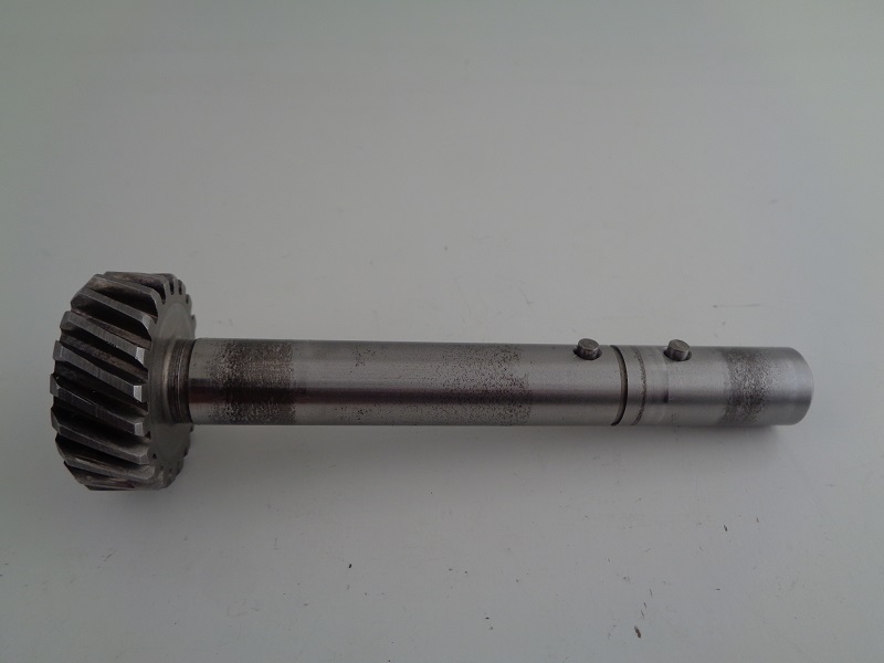
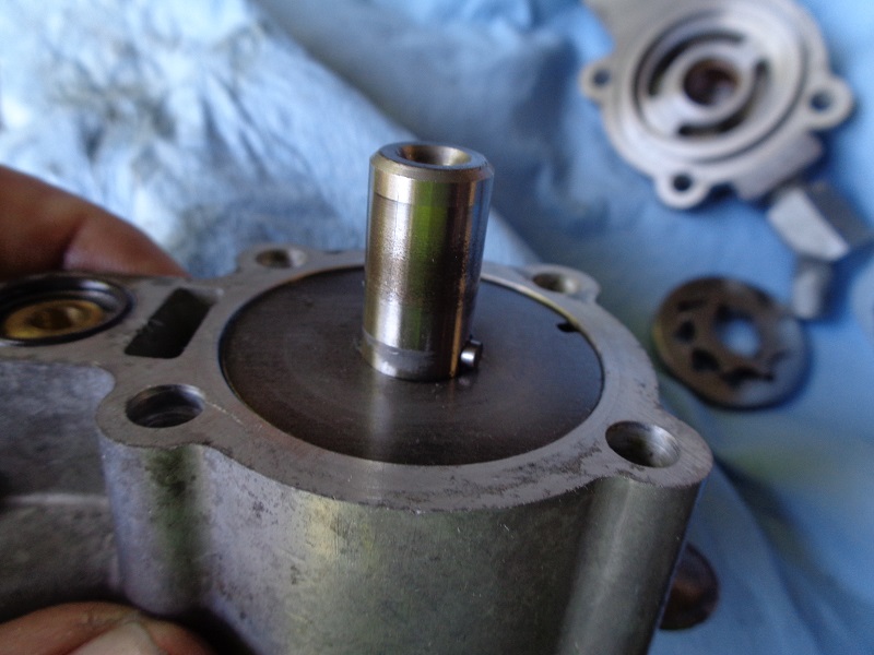
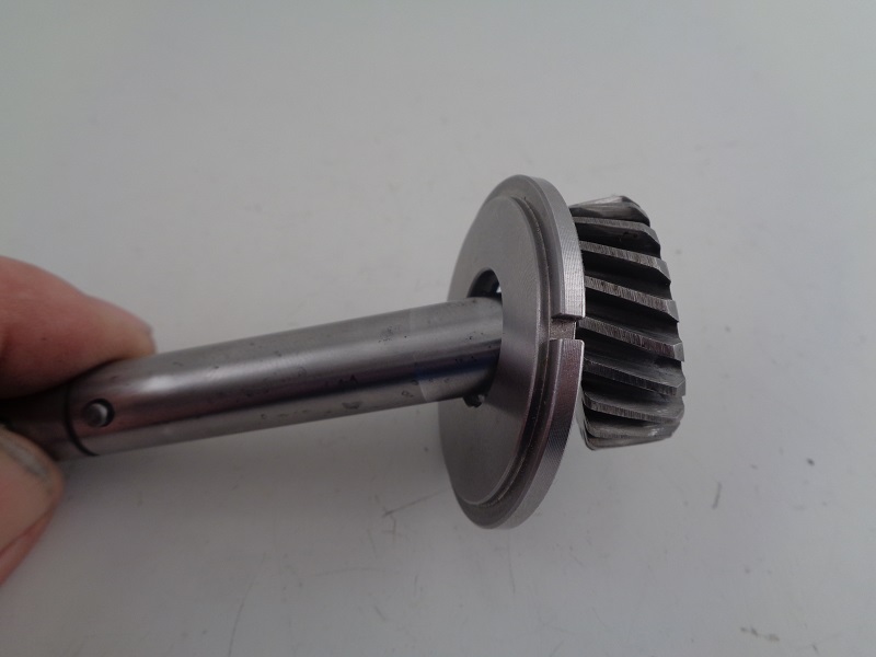
Gearshaft
See also Gear Shaft Dims.
The gear shaft (26488-75) was used from 77-90.
The gear dims and teeth pitch are all the same nominally from 77 to present oil pumps.
However, there are variations of the exact length of the shaft.
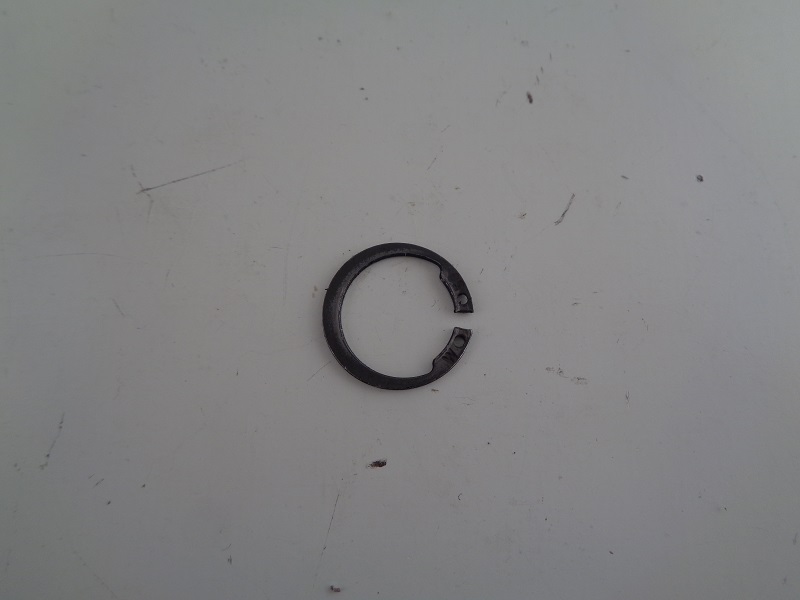
Gear Shaft Retaining Ring
Gear shaft retaining ring (26497-75) was used on 77-90 model oil pumps.
It keeps the inner plate, return gerotors and gearshaft locked in the pump.
It also sets the lowest position for the inner plate and return gerotors inside the pump.
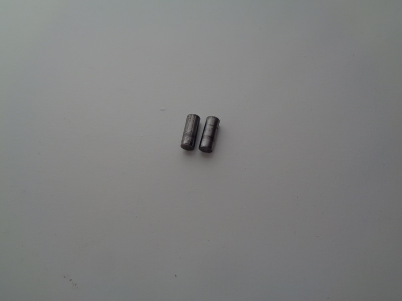
Gearshaft Pins
See also Gearshaft Pin Dims
The gear shaft solid pin (26430-76), not to be confused with a roll pin with a hollow core 10), was used in 77-90 oil pumps.
The diameter and lengths of the pins vary.
The shaft pins don't have to run out and touch the gerotors.
They simply turn both gerotors at the same time.
So, the exact length shouldn't be an issue for the gerotors.
The installed upper pin holds the gearshaft in the pump body during disassembly.
The length of this pin shouldn't be an issue for the gearshaft.
The retaining ring and return gears set the upper positioning of this pin inside the pump.
There is a clearance between the pump bore and the gearshaft.
The upper gearshaft bushing does reach to the end of it's bore in the housing where the pin resides.
So, there is extra clearance between the gearshaft and pump housing bore.
After the retaining ring comes out, the shaft can drop into this tapered bore clearance and the lower pin can scratch the aluminum sides.
The installed lower pin also holds the outer plate in the pump body.
The length of this pin could be a potential issue under the right conditions.
Too short and it could get make it's way into the hole in the plate.
This could induce slop in the plate and allow it to try to spin the plate against the roll pin in the body.
 |  |  |
| Gear shaft solid pins. (26430-76)11) | Pins installed in the gearshaft. 12) | How the pin sits inside the gerotor. 13) |
 |
| Lower shaft pin installed 14) |
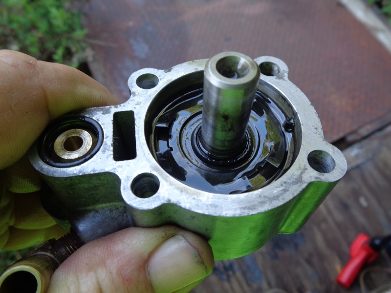
Separator Plates
The 77-90 oil pumps used two plates to separate the feed and scavenge gerotors.
Both plates sit between the feed and return gears and remain stationary during operation.
The plates are separated by a spring washer that puts tension against each plate in opposite directions.
Thus sealing off the feed and scavenge sections.
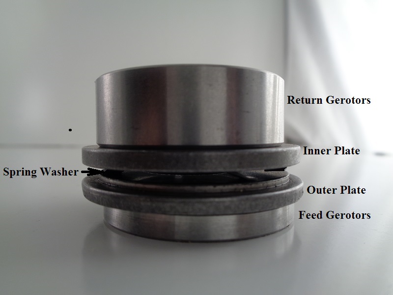 |
| Separator plate locations 15) |
Inner Plate
See also;
Inner Plate Dims
The inner plate part number (26463-77) was used in all 77-90 oil pumps.
It is the top plate (with the pump installed).
The return gerotors sit on this plate.
 |  | 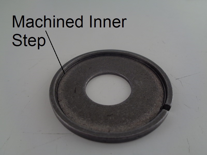 |
| Inner plate (26463-77). Hole for the gearshaft is off center. Machined step is to locate the spring washer between the two plates. 16) | ||
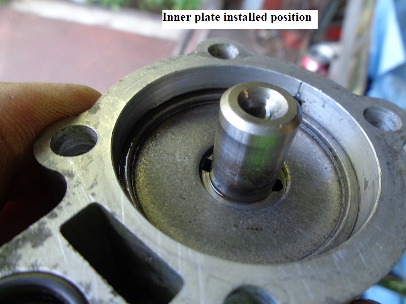 |
| Inner separator plate installed position. (pump upside down) 17) |
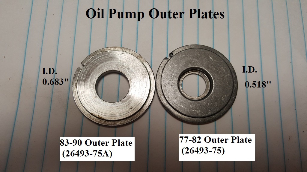
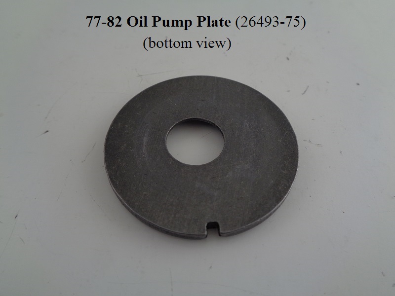
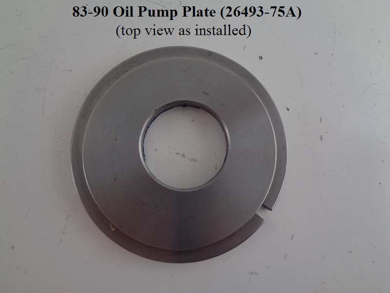
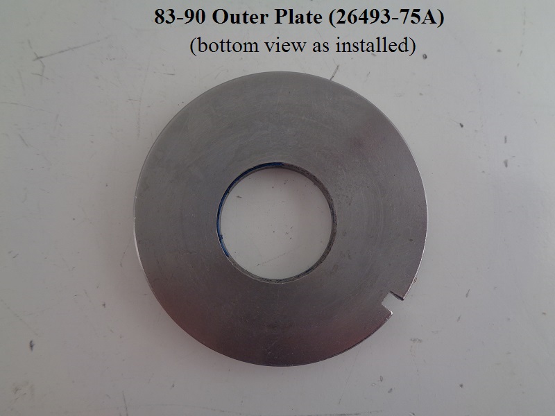
Outer Plate
See also;
Outer Plate Dims
The outer plate is the bottom plate (with the pump installed).
The feed gerotors sit under this plate.
- (26493-75) was used in 77-82 oil pumps.
- (26493-75A) was an upgrade for the E83 pump assembly.
It also was used in the re-designed L83-85 assemblies as well as all 86-90 oil pumps.
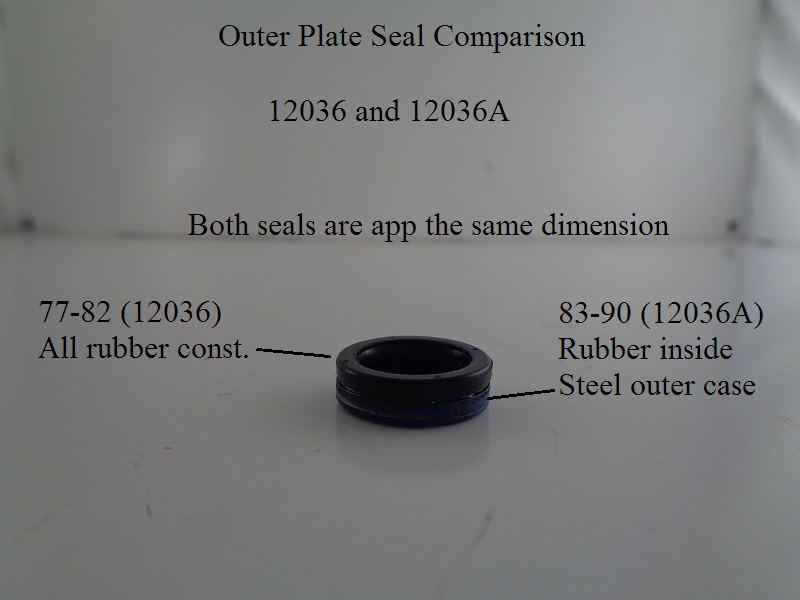
Notice the difference of the cut out or recessed area of the inside diameter of the outer plates.
This is for the different style of seals. 18)
Either plate will fit 77-90 oil pumps with their respective seals.

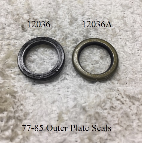
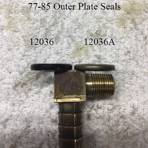
Outer Separator Plate Seal
There were 2 different outer plate seals used on 77-85 oil pumps.
It is supposed to prevent oil from rising into the scavenge gears / engine from the feed section of the pump.
- (12036) was used on 77-82 models.
- Sold for use with outer separator plate (26493-75)
- This seal simply slides down the driveshaft during installation and rests against the inner plate.
- It also covers the retainer ring.
- (12036A) was used on 83-90 models.
- Sold for use with outer separator plate (26493-75A)
- It has a metal outside band with bonded rubber inside.
- It is pressed into the outer plate hole to seal around the driveshaft.

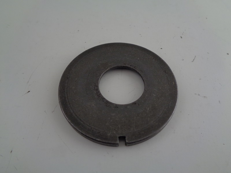
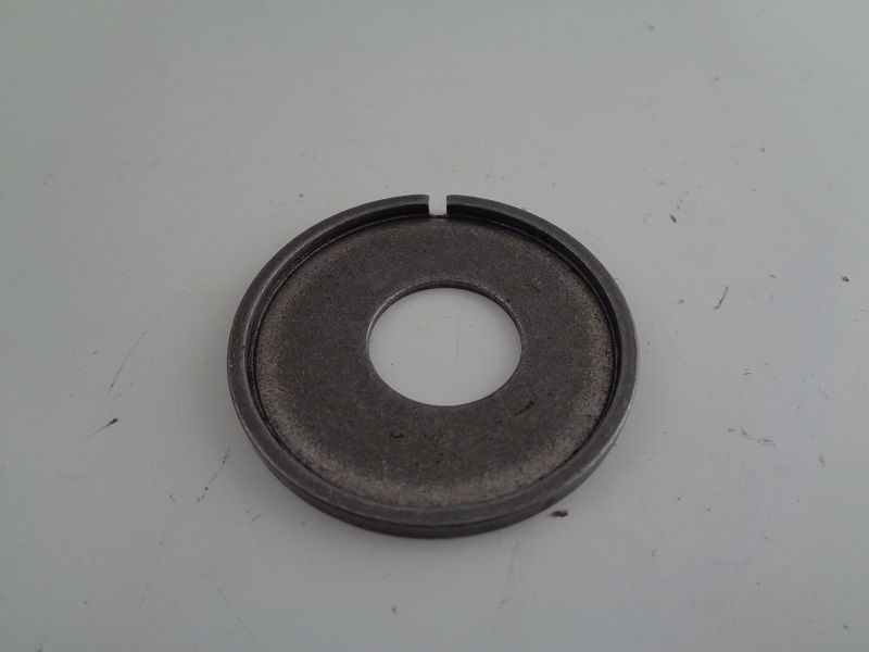
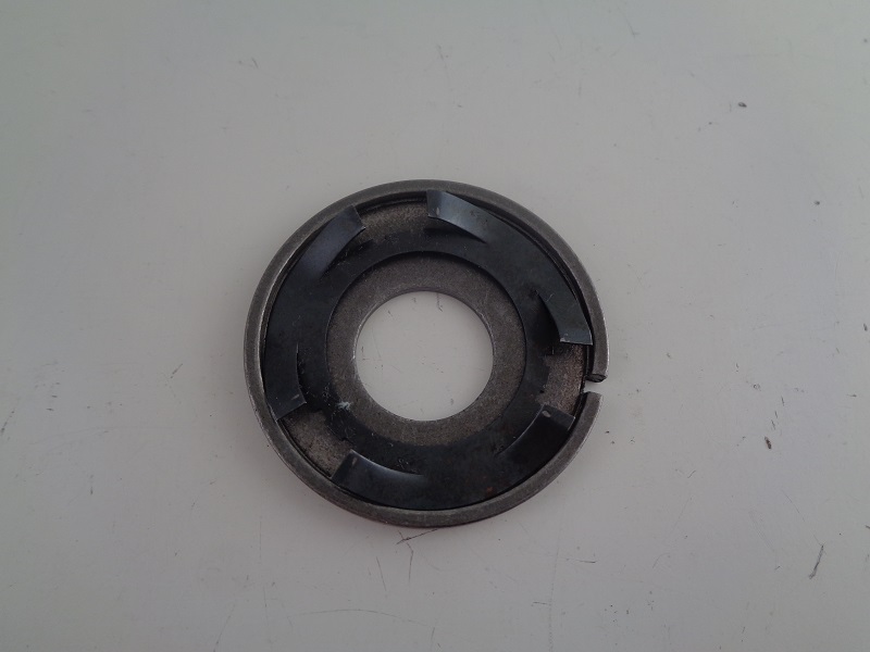
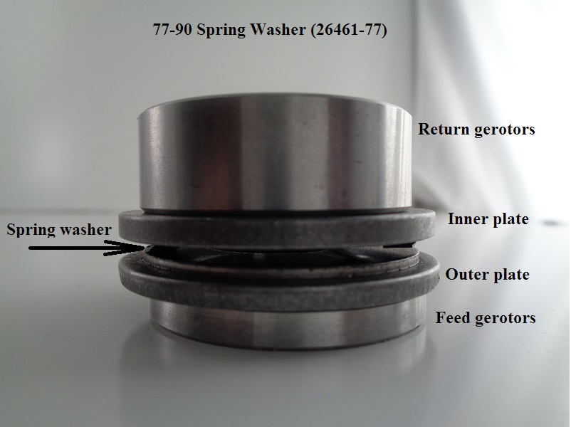
Spring Washer
Spring washer (26461-77) was used on all 77-90 oil pumps.
It sits between the two separator plates and induces pressure against both plates and gerotor sets.
The spring washer is what creates the tension on the drive gear.
 |  |
| Spring washer (26461-77) 32) | |
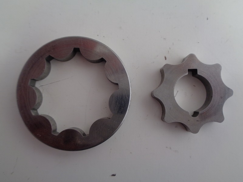
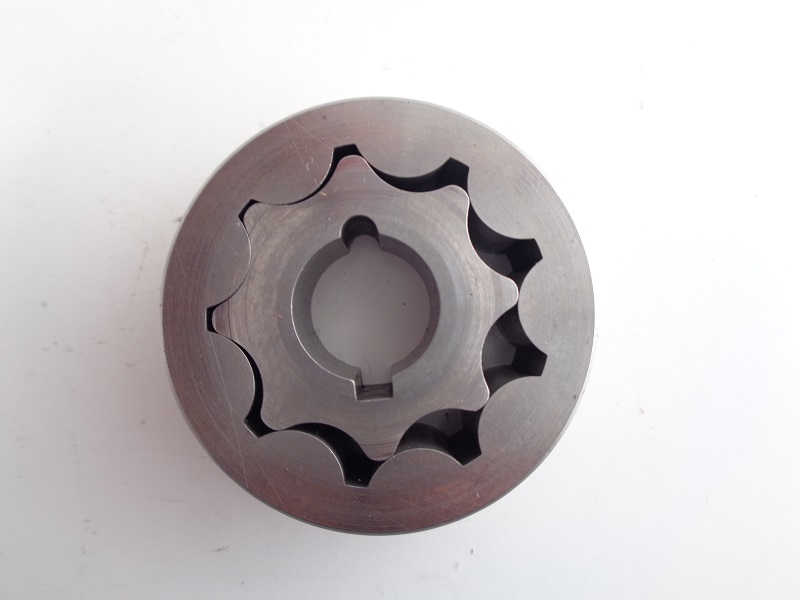
Gerotors
See also;
Gerotor Dims
- The inner gerotor gears are locked in place by the solid steel pins protruding from the gearshaft.
- They turn in the same direction as the gearshaft.
- The outer gerotor gears spin by the teeth of each inner.
- They also turn in the same direction as the gearshaft.
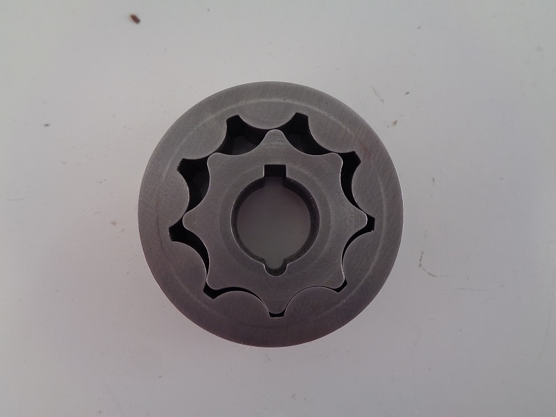
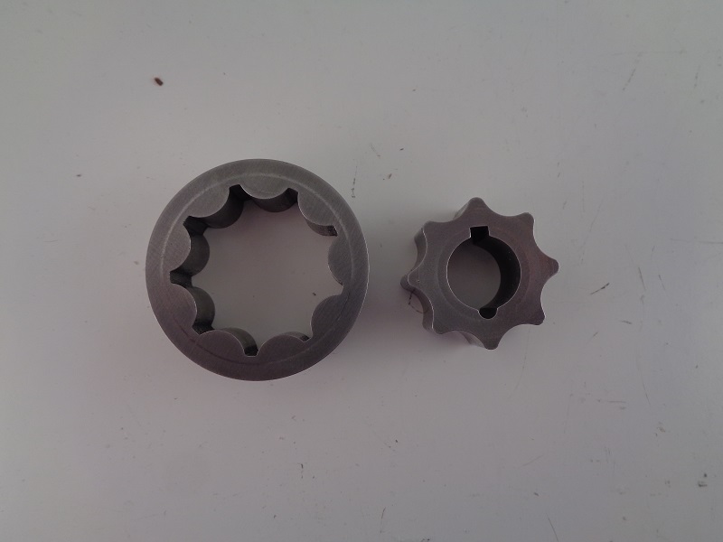
- The gearshaft is off center to the outside gerotors both feed and return.
- There are 8 teeth on each inner and 9 on each outer gerotor set.
- This allows for the cavity between the inner and outer gears for oil transfer.
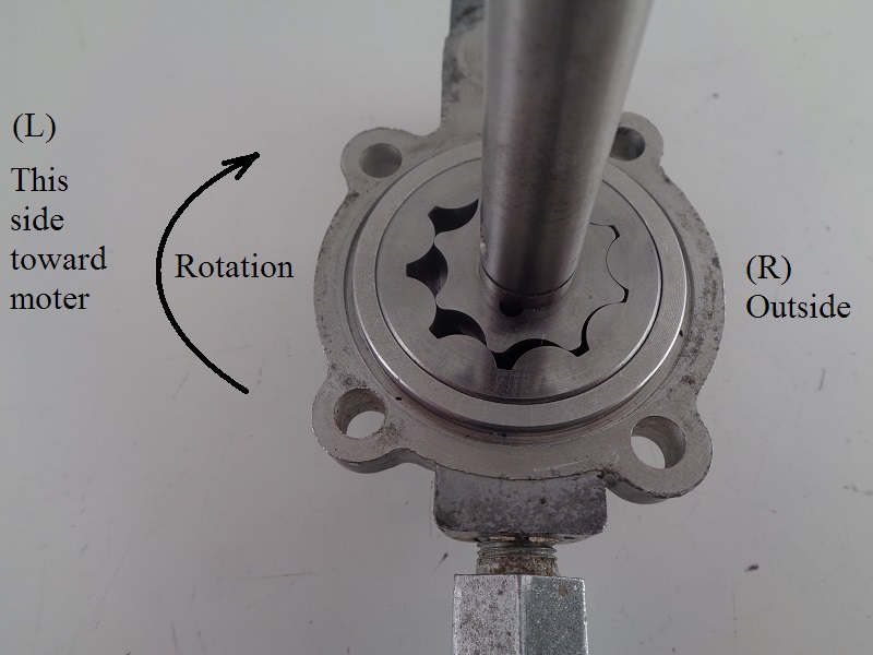
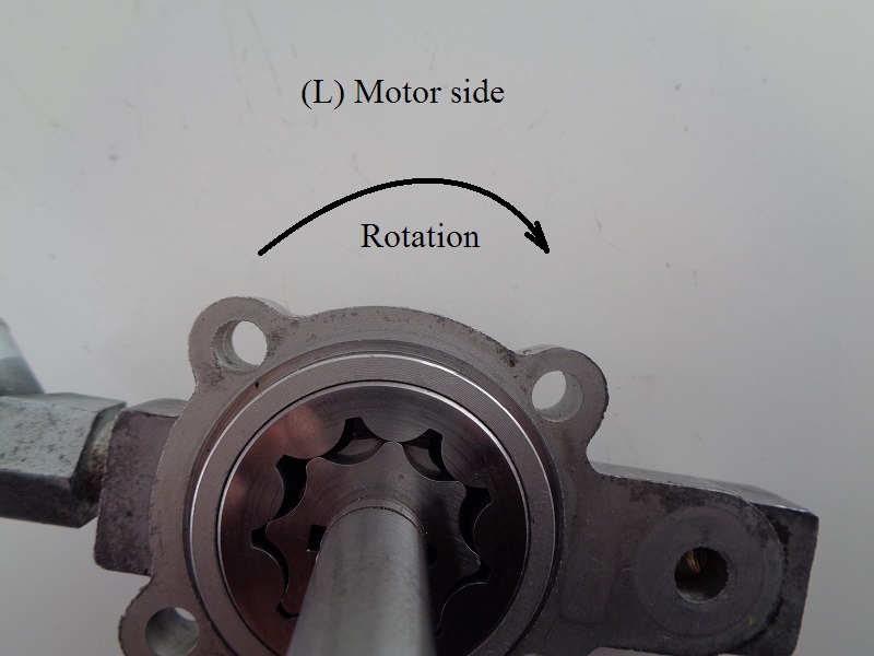
- The side toward the motor is where oil is transferred to and from the pump.
- The inner and outer gears come together on the other side (right side).
- This spacing relationship doesn't change between the motor side or the outside of the pump due to the offset gearshaft.
 |  |
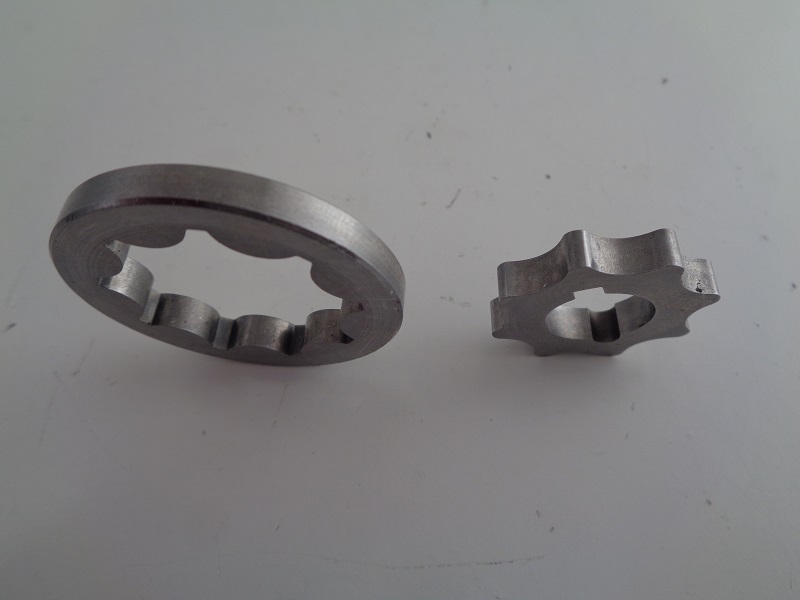
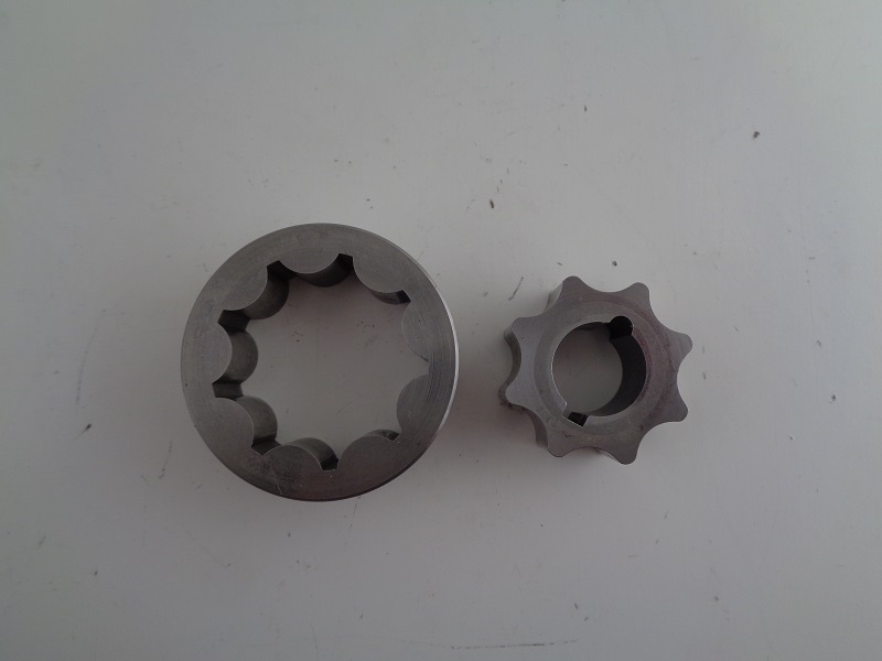
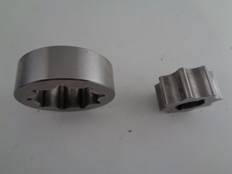
- There were 2 different sets of gerotors used in Sportster oil pumps from 77-85.
- 77-E83 (chamfered edges); Return set (26491-75), Feed set (26492-75).
- Discontinued for production models by November of 1982. 36)
- Sold for 77-E83 oil pumps through 1984.
- L83-85 (straight edges); Return set (26491-83), Feed set (26492-83).
- Used on production models from L83-85.
- The only year these were available for parts order as a set was 1985.
(otherwise the only way to buy them was to buy the L83 oil pump assembly) - The original gerotors remained available for 77-82 oil pumps.
(and the E83 pump) - The same return gears (26491-83) were used in 86-90 oil pumps.
(however, the feed gears were changed) - So only the scavenge gears were available from 86-90.
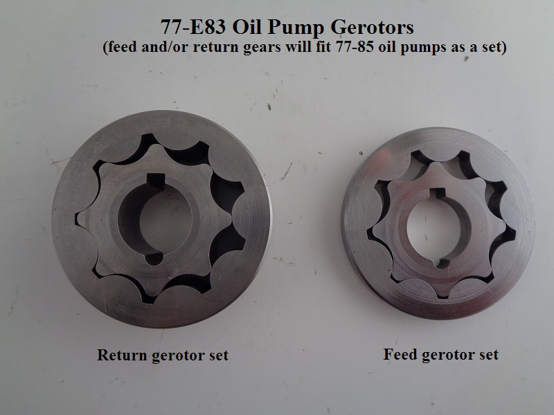 |  |
| 77-E83 return (26491-75) and feed (26492-75) gerotors 37) | |
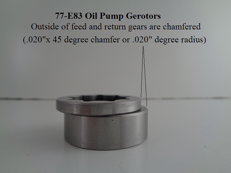
Late 1983 oil pump assembly design modification
- Late 1983 pump bodies and covers were also under-cut or relieved to accommodate for clearances with the new gerotors.
- The 77-E83 chamfered gerotors have a (.020“ x 45° chamfer or .020”) radius and the same radius is designed into their respective oil pump body / cover.
- The Late 83 pump body and cover has a (.010“ max. radius) undercut for clearance designed into them.
- These modifications limit interchangeability and affect the installation of repair parts:
- Either early style or late style gerotor gears may be used with late style (under-cut) oil pump bodies and covers.
- Only early style chamfered gerotor gears may be used with early style oil pump bodies and covers
(Use of late style gerotor gears in early style oil pump bodies AND covers could cause the oil pump to bind up and possible pump failure).
When non-chamfered gear sets are used, the pump body or cover must be changed.

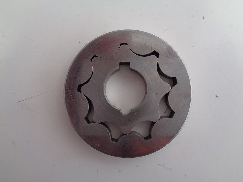
Feed Gears
77-E83
Feed gerotors (26492-75):
These can also be used on L83-85 oil pumps. 43)
 |  |  |
| 77-E83 feed gerotors (26492-75) 44) | ||
 |
| 77-E83 feed gerotors installed position 45) |
L83-85
(26492-83) Straight cut feed gerotors.
Return (scavenge) Gears
77-E83
(26491-75) Chamfered return gerotors.
These gerotors can also be used in L83-85 oil pumps. 46)
 |  |  |
| 77-E83 return gerotors (26491-75) 47) | ||
 |
| 77-E83 return gerotors installed position 48) |
L83-90
(26491-83) Straight cut return gerotors:
 |  |  |
| L83-90 return gerotors (26491-83) 49) | ||
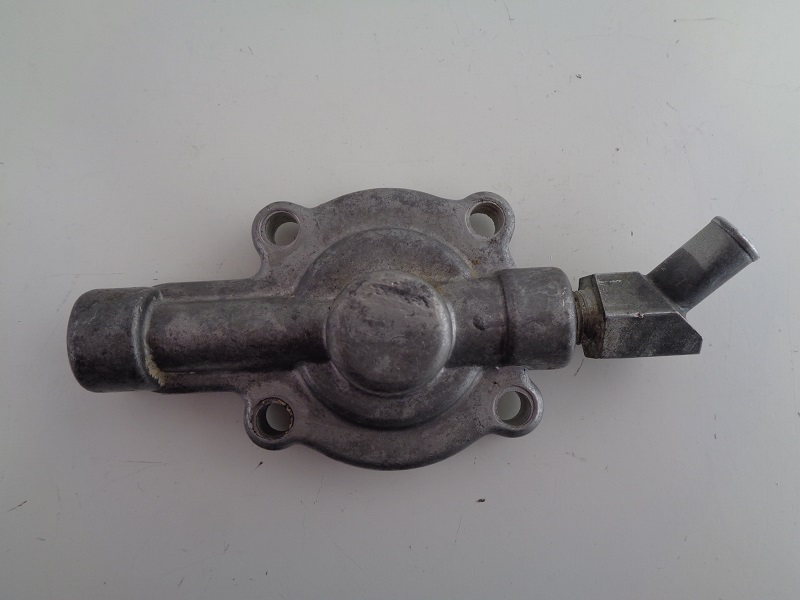
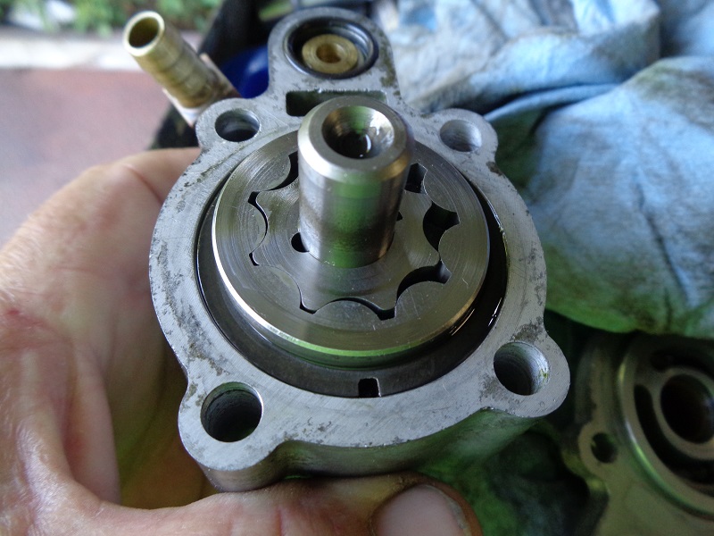
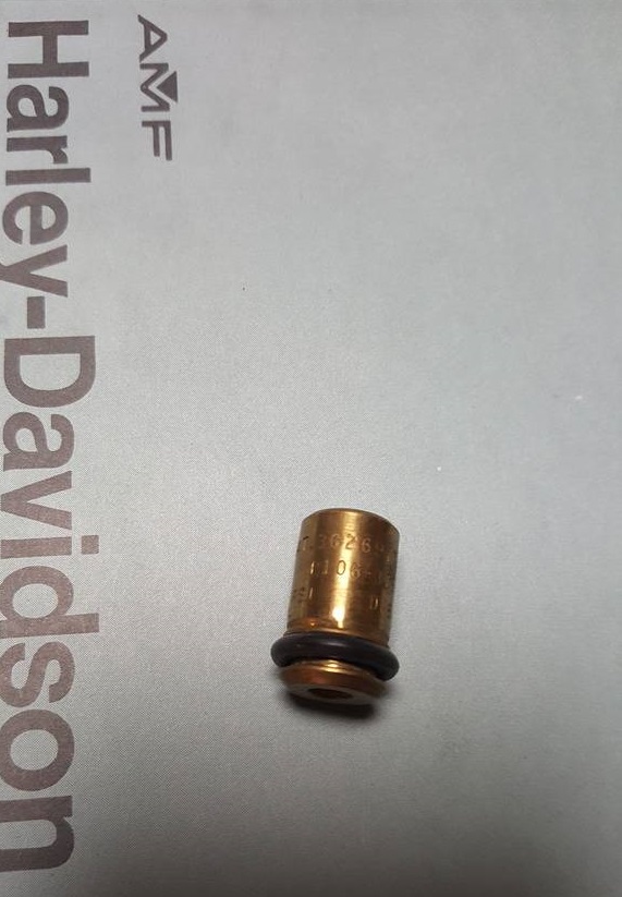
Check Valve
See also;
Check Valve Dims
More on how the check valve works
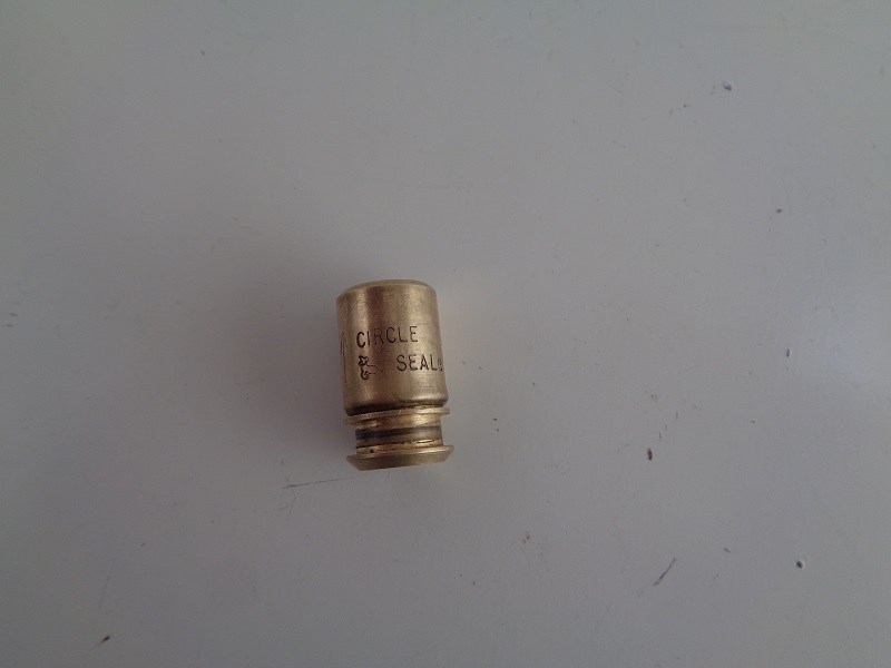
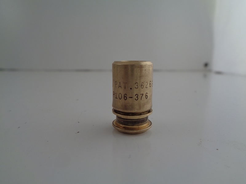
Made by Circle Seal.
Manufacturer Part# P106-376.
HD Part# (26435-76A).
Patent #3626977.
Check valve (26435-76A) was an upgrade in L77 and used on all L77-85 models.
It has an arrow on the side for proper installation pointing up with FC to the bottom left of the arrow.
- The oil pump check valve plays a role in the operation of the oil pressure switch.
- It also stops oil from entering the engine when the engine is shut off (in theory).
- The check valve had 2 different part numbers.
- The original was (26435-76) in 1977.
- Speculation could say…,
- The original check was for the special “1600” pump (discontinued L77).
- And the upgraded check was for installation in a newer, non publicized, pump casting not cataloged.
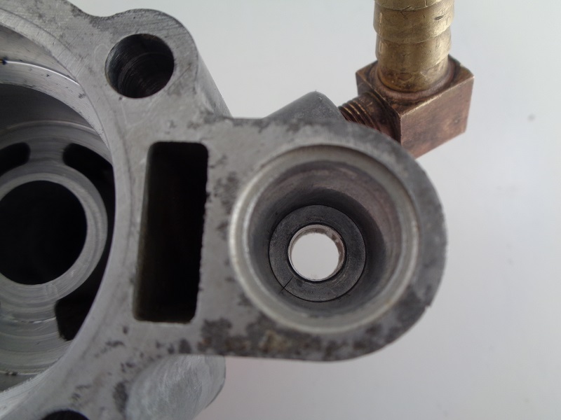 | 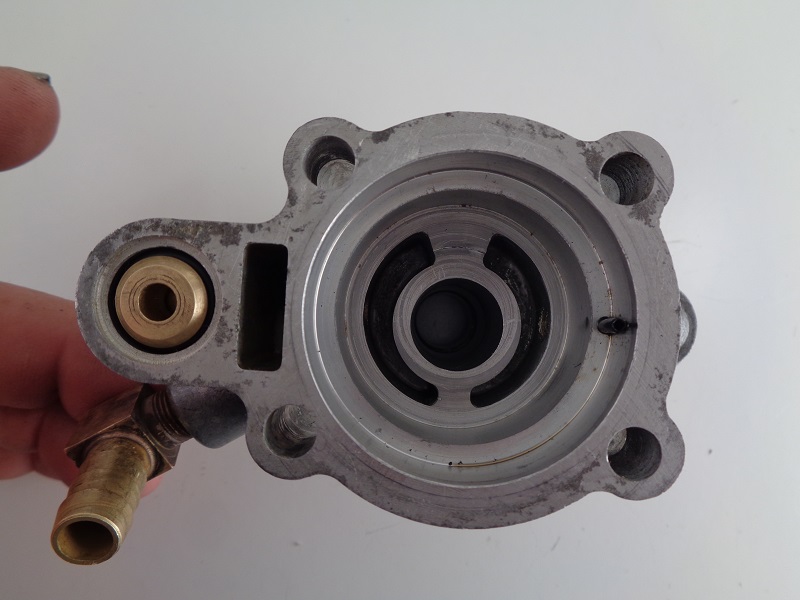 |
| The check valve sits inside the bore in the pump body as shown. Installed position (R)55) | |
In search of a comparable check valve
The closest on the Circle Seal website is a 2900 series cartridge check valve.
Click on the 2900 series in the catalog section to the left on the their site.
In the Products-Engineering-Terminology PDF;
Flow capability (Cv=0.55). Flow capability indication commonly accepted by the valve industry. The literal definition is that a component with a Cv of one (1);
Can flow one (1) gallon of water with a ΔP of one (1) PSI.
The calculated results from Cv equations must be considered reasonable approximations only.
Link to the Circle Valve site with comparable dims and specs:
https://catalog.circlevalve.com/item/check-valves/c2900-series-cartridge-check-valve-0-to-3000-psig/cs-c2949b-4q
This one has a back-up O-ring on the valve.
That link came from this XLF thread:
https://www.xlforum.net/forum/sportster-motorcycle-forum/sportster-motorcycle-era-specific-and-model-specific/ironhead-sportster-motorcycle-talk-1957-1985/184257-oil-pump-porn/page2?t=1979566&highlight=gerotor&page=2
Oil Pressure Switch
See also;
Tesing the Oil Pressure Switch
More on How the Ironhead Oil Pressure Switch Works
(26554-77) Oil pressure switch was used on L-77 to 90 models.
On 77-85 models, it was mounted at the oil pump and later mounted to the filter pad on 86-90 models.
The oil pressure switch was listed in the -77A parts supplement catalog.
However, it was listed as a L77 addition in the -78 parts supplement.
The circumstance of this switch being a late addition is unclear.
However, there was a wiring harness upgrade in 78 and an oil pressure gauge available for 77-78 models.
Double nuts (7638) for the oil pressure switch were also a late addition part #.
(retainer for the wire to the oil light)
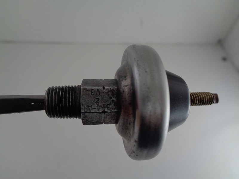 |  | 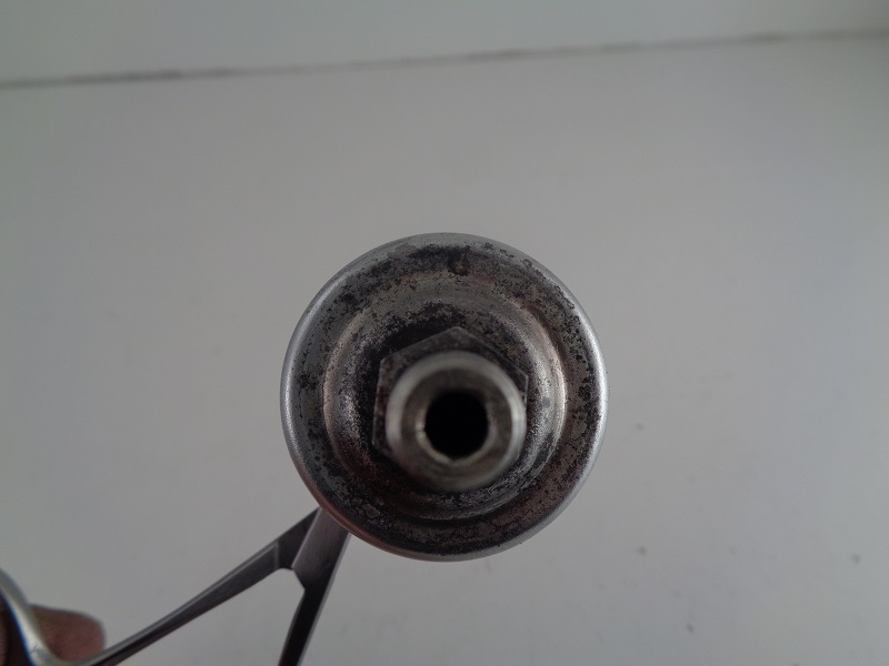 |
| Oil pressure switch (26554-77) 56) | ||
4)
, 6)
, 8)
, 9)
, 11)
, 12)
, 13)
, 14)
, 15)
, 17)
, 20)
, 21)
, 22)
, 23)
, 24)
, 25)
, 26)
, 28)
, 29)
, 30)
, 31)
, 33)
, 34)
, 35)
, 45)
, 48)
, 55)
, 57)
photo by Hippysmack
19)
photo by DirtyCory of the XLFORUM, annotated by Hippysmack https://www.xlforum.net/forum/sportster-motorcycle-forum/sportster-motorcycle-era-specific-and-model-specific/ironhead-sportster-motorcycle-talk-1957-1985/194881-let-s-study-the-77-85-oil-pump-parts-and-changes-and-when?t=2071153
39)
HD Service Bulletin #M-892 dated June 22, 1984
40)
79-85 HD XL models Parts Catalog -85A pg 21
50)
1954-1977 HD Sportster XLH/XLCH-1000 Parts Catalog Supplement (99451-77A)
51)
1954-1978 HD Sportster XLH/XLCH-1000 Parts Catalog Supplement (99451-78)
52)
1954-1977 HD Sportster XLH/XLCH-1000 Parts Catalog pg 23 (99451-78A)