Table of Contents
This is an old revision of the document!

EVO: Body Parts
FUEL TANKS
☚—————– ALSO CHECK OUT THE TANKS IN THE GAS TANK GALLERY ————-—-☛
Sub Documents
| 82-85 Ironhead tanks are the same as 1986 Evo |
| Stock Tank Features As Supplied on Different Models | |||||
| Petcock is | Mount is Rigid/Grommet | ||||
|---|---|---|---|---|---|
| Year | Models | TankSize | Rt/Lt/Man/Vac | RrEars Down/UnderSeat | Notes |
| 86-91 | All | 2.25gal | RtSide/Man | Rigid - Down | (TwistOn-Cap/61102-83C) |
| 92 | All | 2.25gal | RtSide/Man | Rigid - Down | (ScrewIn-Cap/61272-92) |
| Option | 3.25gal | LtSide/Vac | Rigid - Down | (1992 P&A Catalog Option) | |
| 93-94 | All | 2.25gal | RtSide/Man | Grommet - Down | |
| Option | 3.25gal | LtSide/Vac | Grommet – Down | (1994 P&A Catalog Option) | |
| 95 | 883 | 2.25gal | LtSide/Vac | Grommet - Down | |
| 1200 | 3.25gal | LtSide/Vac | Grommet - Down | ||
| 96 | 883 | 2.25gal | LtSide/Vac | Grommet - Down | |
| 1200 | 3.3gal | LtSide/Vac | Grommet – Down | (w/RoundedBottomEdge) | |
| 97-98 | All | 3.3gal | LtSide/Vac | Grommet - Down | Primed part # (61348-03)1) |
| 99-03 | All | 3.3gal | LtSide/Vac | Grommet - Down | |
| 04-06 | Std/L/R | 3.3gal | LtSide/Vac | Rigid – Under Seat | (883Std&1200R&883L&883R) |
| 8C/12C | 4.5gal | LtSide/Vac | Rigid - Under Seat | (883C&1200C) | |
Starting in 2007:
- No petcock - Electronic Fuel Pumps implemented on all tanks
- Tanks are rigid mounted because engine is rubber-mounted
- Tanks have rear mount under seat (but different from 04-06)
- All tanks mount the same 2007-17 - These three primed tanks are available:
- 2.1gal Prime 61724-10 «-back to 2010
- 3.3gal Prime 61405-07 «-back to 2007
- 4.5gal Prime 62213-07 «-back to 2007
| Stock Tank Sizes As Supplied on Different Models (All Capacities are in Gallons) | ||||||||||||||
| 2007 | 08 | 09 | 2010 | 11 | 12 | 13 | 14 | 15 | 16 | 17 | 18 | 19 | 2020 | |
| 883 Standard | 3.3 | 3.3 | 3.3 | |||||||||||
| 883L Low/Superlow | 3.3 | 3.3 | 3.3 | 3.3 | 4.5 | 4.5 | 4.5 | 4.5 | 4.5 | 4.5 | 4.5 | |||
| 883C Custom | 4.5 | 4.5 | 4.5 | 4.5 | ||||||||||
| 883R Roadster | 3.3 | |||||||||||||
| 883N Iron (Nghtsr?) | 3.3 | 3.3 | 3.3 | 3.3 | 3.3 | 3.3 | 3.3 | 3.3 | 3.3 | |||||
| 1200N Nightster | 3.3 | 3.3 | 3.3 | 3.3 | 3.3 | 3.3 | ||||||||
| 1200C Custom | 4.5 | 4.5 | 4.5 | 4.5 | 4.5 | 4.5 | 4.5 | 4.5 | 4.5 | 4.5 | 4.5 | |||
| 1200L Low | 4.5 | 4.5 | 4.5 | 4.5 | 4.5 | |||||||||
| 1200T SuperlowT | 4.5 | 4.5 | 4.5 | 4.5 | ||||||||||
| 1200R Roadster | 3.3 | 4.5 | ||||||||||||
| 1200X Model 48 | 2.1 | 2.1 | 2.1 | 2.1 | 2.1 | 2.1 | 2.1 | |||||||
| 1200V Model 72 | 2.1 | 2.1 | 2.1 | 2.1 | 2.1 | 2.1 | ||||||||
| XR1200/XR1200X | 3.5 | 3.5 | 3.5 | 3.5 | ||||||||||
| 1200-Model50-Annv | 3.3 | |||||||||||||
Notes
Generally, you can _make_ tanks interchange between '82 to '03 - Mounting holes are at the same place, but some are rigid mount & others rubber grommet mount.
Screw-in Caps from 1992-later are generally interchangeable although some part number variations do exist for different models and years.
All 86-06 tanks (non-EFI EVO engines) use 22mm petcocks. EFI models (2007-later) have fuel pumps. (Some Ironhead tanks use 22mm petcocks.)
There are adapters available to replace the EFI fuel pump plate with a flat-plate to create a tank outlet for mounting a petcock. This may allow the use of a tank intended for EFI models on customized carburetored models. See this XLForum Thread.
Reference Threads
http://xlforum.net/forums/showthread.php?t=1969877
http://xlforum.net/forums/showthread.php?t=652141
Petcock (Fuel Outlet)
![]()
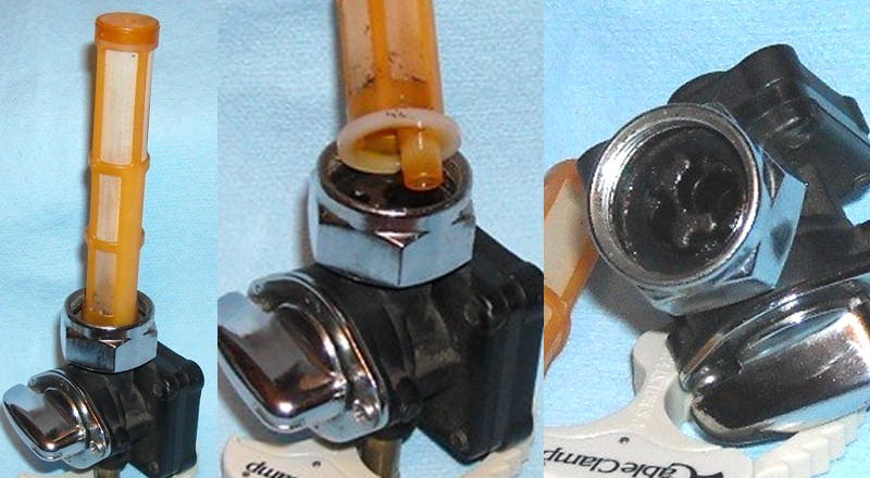
The Petcock allows control of the fuel to the carburetor from the fuel tank. It has a 3-position lever to create OFF, ON & RESERVE settings. The OFF setting prevents fuel flow to the carb (used whenever the bike is not running). The ON setting allows normal fuel flow to the carb when the tank is above the reserve level. The RESERVE setting allows the final amount of fuel to be sent to the carb until the tank is empty. Normally, the petcock has an in-tank cylindrical mesh filter enclosing these inlets to prevent any dirt in the tank from clogging the intake of fuel. The tank and filter may be required to be cleaned from time to time. 2)
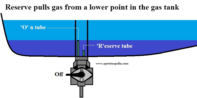
The petcock creates two levels of fuel supply in the fuel tank, the higher level being used for the ON setting and a low level being used for the RESERVE supply level. To do this, a short tube protrudes vertically into the fuel supply to create an ON level. A shorter tube (or the base of the petcock) is used to supply fuel ONLY when the petcock is set to RESERVE. By drawing fuel from the taller tube when the petcock is set to ON, a 'reserve' is created (usually between 10% & 20% of the tank size) below that tube level so as to warn the rider that the tank is running low on fuel.
When the fuel level drops below the level of the taller ON tube, the engine will sputter or die. The rider needs to switch to the RESERVE setting in order to use the final amount of fuel in the tank - and get to a fuel station before running out completely.


Starting in 1992, when there was an option for a 3.25gal Sportster tank, the petcock specified was a new, vacuum-operated design. It had an automatic shutoff function that used a vacuum hose connected to the carburetor (tee'd off the hose to the VOES) to operate a diaphragm in the petcock. This diaphragm had a short plug that protruded into the fuel flow cavity, and held there by a spring, to prevent fuel flow until there was enough vacuum to pull the diaphragm/plug out of the cavity.
This was considered a safety feature to help riders who forgot to turn the petcock to the OFF position (and to help prevent fuel spills in case of an accident or tipover). It was the recommended petcock for all optional tanks from 1992-1994. This style petcock was implemented on all stock tanks (of any size) from 1995 thru 2006 (2007-later used electrical fuel pumps). A vacuum of approximately 0.5-1.0 in. of Mercury (Hg) was needed to open the petcock for fuel flow.4) The OFF setting was still recommended whenever the engine was not running (to prevent accidental fuel flow from a faulty vacuum diaphragm).


Notice that the kidney-shaped cavity on the knob allows, in one position, the ON tube to flow to the outlet and, in another position, it allows the RES(erve) tube to flow to the outlet. The middle knob setting (as the switch is shown in the picture with the kidney-shaped cavity at the bottom only) is the OFF setting. If you look carefully inside the outgoing cavity of the petcock body, you can see the vacuum stud which allows fuel flow when the vacuum pulls the stud/plug open. The petcock is designed to ONLY FLOW FUEL when there is a vacuum applied. With no vacuum, the stud is in place and no fuel can flow, no matter where the knob is set.
There are a number of Petcock valves available, most using 62169-xx, where the xx is a number and revision letter. The older versions (like 62169-81) do not use a vacuum valve. Later, among the vacuum versions (such as 62169-95/A/B/C & 62169-02/A) there were versions with a left-direction fuel outlet tube while others have a downward fuel outlet tube. Some versions have a handle where the long portion is the pointer to the mode and others use the shorter end of the handle to indicated the valve mode (as in On, Off, Res).
INSTALLING THE PETCOCK
These petcocks use a multi-threaded nut to attach the petcock to the tank. One thread set is for the petcock (fine threads) while the other set is for the tank outlet (coarse threads). The principle here is that as you thread the nut onto the coarse threads of the tank, it is tightening faster there than the fine threads are unscrewing at the petcock. This difference in thread tpi, pulls the petcock up against the tank outlet. The shoulder of the in-tank filter functions as the seal between the petcock and the tank (or there may be an additonal washer or o-ring as a seal).
You must wind the nut down on the petcock before starting to attach the petcock to the tank. Place the petcock close to (but not against) the tank outlet. You want the nut to securely screw onto the tank threads (several threads) before the petcock is pulled tight to the tank outlet. As you thread the nut onto the tank, it is unscrewing (more slowly) from the petcock. If you start to thread the nut onto the tank outlet with the petcock too far away, you will run out of threads before the petcock is pulled tight to the tank outlet. If you start with the petcock too close to the tank, the petcock will be pulled tight to the tank after barely starting the nut onto the tank outlet. You're looking for a balance here.
It may take a time or two of testing to see just how close you want the petcock to the tank as you start to thread the nut onto the tank outlet. Success is when the petcock is properly tight to the tank with a relative equal number of nut threads holding onto the petcock and the tank outlet.
Additional References:
Vacuum Operated Fuel Supply Valve Kit - (Instruction Sheet '-J02634' - Kit# 62169-95C)
https://serviceinfo.harley-davidson.com/sip/content/document/view?id=1877
https://serviceinfo.harley-davidson.com/sip/content/document/view?id=1419768648772055282
Failures
If you get fuel flow thru the petcock to the carb with no vacuum applied (in any petcock position), there is a problem with the petcock seals.
When the petcock vacuum-diaphragm is cracked or torn, it may not open the fuel flow enough to operate the bike at full speed. The fuel flow will be restricted because the diaphragm will not pull the plug fully out. Also with a faulty diaphragm, it can leak fuel down the vacuum hose to the carb. This creates an overly rich fuel-mix condition.
So, depending on exactly how the petcock fails, you might get a too rich or a too lean condition.
Manual petcocks can also fail. They can leak fuel from the seals. They can collect debris on the filter screens. If the filter fails, it can allow debris into the operating petcock and clog the passages.
NOTE - PRODUCT RECALL:
2005 Petcock Recall Notice - http://xlforum.net/forums/showthread.php?t=95982
Summary: Certain motorcycles may have been produced with defective fuel shut-off valves. The functionality of the 'ON' position and the 'Reserve' position of the valve may have been reversed.
Bypassing the Vacuum Function
If you prefer not to use the vacuum valve to control the fuel flow, you can disassemble the petcock & reverse the spring/diaphram assembly. 7)
You would need to remove the four rear screws of the vacuum section. Remove the spring & remove the diaphragm. Then put the spring on the stud of the diaphragm (which normally operates as the plug) and reassemble the diaphragm back into place. The spring will now hold the diaphragm in an open position. Fuel should flow through the petcock without a vacuum line connected to it.
If you remove the vacuum function from the petcock and you have one of the older models with a tee fitting in the vacuum line (that goes to the VOES/MAP), then remove the tee and run a straight line from the carb vacuum nipple directly to the VOES / MAP. This minimizes any leak points. If you have a 2004-2006 model (with the MAP sensor on the intake manifold) and remove the vacuum function from the petcock, you can remove the vacumm line completely and simply cap the vacuum nipple on the carb.
There are also kits that replace the rear vacuum section of the petcock with a solid blank plate.
| Decman of the XLForum said: I had this bypass kit in my tool box. It's a flat plate and rubber gasket. About a week after I installed it, the bike started to stall after warmed up due to no fuel. When I took the petcock apart it was obvious that the center of the rubber gasket was stretching and being pulled into the fuel cavity and shutting off the fuel. Doh! So I just cut a hole in the center of the gasket and all is well. After a quick search on the net I found that the new kits come with the hole already there now. |  8) 8) |
Troubleshooting
| PROBLEM | CAUSE | SOLUTION |
| Vacuum valve not opening | Vacuum hose not connected to vacuum nipple | Connect hose to vacuum nipple |
| Leaking diaphragm | Replace entire valve assembly | |
| Vacuum hose assembly pinched or cracked | Replace vacuum hose assembly | |
| Vacuum valve does not close | Damaged sealing surface on valve side of diaphragm | Replace entire valve assembly |
| Broken or missing internal spring | Replace entire valve assembly | |
| Valve leaks gasoline at bottom nipple | Leaking diaphragm | Replace entire valve assembly |
| Loose diaphragm housing screws | Tighten screws |
Vacuum Test the Petcock
You can vacuum test the valve using the procedure below: 9)
- Connect a MityVac (or similar hand operated vacuum pump), vacuum line and suitable vacuum fitting to the vacuum port of the fuel supply valve.
- Run a section of clear fuel line from the fitting on the fuel supply valve to a gas can.
- Pull 25 in. Hg vacuum and release.
Check for fuel flow while applying vacuum and check that the fuel stops flowing shortly after vacuum is released. - Repeat step 3 five times, each time checking for fuel flow at vacuum and no fuel flow shortly after vacuum is released.
On fifth application of vacuum, pause with vacuum applied, and check for slow leaks. Release vacuum. - If no leaks were present, go to the next step.
- Disconnect the hand held vacuum pump and fuel line.
- Position a new hose clamp on the fuel hose and install the fuel hose to outlet fitting on the valve body.
- Install the vacuum hose to the valve nipple.
Vapor Valve (Tank Venting)
From the 2003 Sportster Service Manual
(Fuel Tank section)
“The fuel tank is vented through a standpipe (vent tube) within the tank. A hose at the base of the fuel tank is connected to the standpipe.”
“The fuel tank vapor hose is connected to a vapor valve located beneath the seat between the oil tank and the battery tray. ON non-California models, another hose connects the vapor valve bottom fitting to a hollow frame member. On California models, the bottom hose is routed to the carbon canister.”
“Mount the vapor valve in an upright position with the longer fitting positioned at the top or excessive fuel vapor pressure may build up within the fuel tank.”
(CA EVAP section)
“If the vehicle is tipped at an abnormal angle, the vapor valve closes to prevent liquid gasoline from leaking out of the fuel tank through the vent hose.”