Table of Contents

REF: General-MSR 07
Diagnosing Catastrophic Engine Failure in Evo Engines
Determining the exact cause of an engine seizing up is often not that easy.
However, failure analysis is essential to solving future problems and learning in real time.
It's kind of a cascading problem since when one part fails, other parts are damaged also and the hunt begins uncovering similar causes and affects.
It could be described as a “Chicken or the Egg Syndrome”. Spun cam bushings are usually thought of as a poor oiling issue.
This might cause enough heat to expand their bores and loosen the bushings, allowing them to seize to the spinning cams.
But there many more considerations for what spun the bushings than just an oiling problem as you can see below.
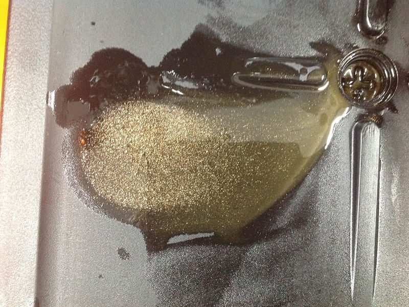
If something like this comes out when you do an oil change, find out if it's metal or brass / bronze and start diagnosing where it came from.
The Teardown
- Diagnosis begins before and during teardown as well as during installation of new parts.
- Inspect and mic everything as you tear it down as well as during the install.
- Take pictures of everything (outside and inside before you remove anything, during and after).
After you have the entire engine spread out in pieces is the last time to wonder if you had a pinched oil line since you can't prove it then. - Work backwards from the order of installation when removing anything. Just crack them loose in reverse order, then back them off in reverse order. 2)
Try and take pics, just for you, (although we'd like to see them too) before, during and after teardown.
Possible Causes of Spun Cam Bushings
On the cam bushings in either the cover or cases you have 3 different metals (brass/bronze/metallic) with different expansion rates so what really happens? 3) 4)
As soon as there is initial movement of the bushing, the oil feed hole doesn't line up.
After that the outside of the bushing is being oiled more than the inside of the bushing. 5)
Installation Errors
These items will begin a natural degradation of improper oiling and / or heat related failures:
- Installing Cam Bushings:
- The OD of the bushing should match the ID of the bore before installation. That has to be measured before installing the bushings.
- Bushings not reamed to proper clearances using the service manual.
- Bushings not properly seated during installation. Each bushing has to butt into the cam wall. That sets the proper side play.
If the bushing doesn't install against the cam wall, side play is to little which creates heat during operation.
- Installing Cams:
- Camshafts and bushings not properly lubed for initial start-up.
All cam gears, shafts and their associated bushings should be slathered in thick lube during installation else initial startup could create enough heat to spin the bushings. - Insufficient clearance between the camshaft and the bushing.
The FSM also has a minimum spec for clearance during installation of the cams. This gives room for both lubrication and accounts for thermal expansion.
Clearances set too low will result in the bushing growing into the shaft during operation and insufficient lubrication for heat control.
This will create enough metal to metal heat to lock the bushing to the shaft. The spinning camshaft then spins the bushing out of it's bore. - Excessive clearance between the camshaft and the bushing.
The FSM has a maximum spec for clearance during installation of the cams.
This can break the hydraulic seal needed to keep enough oil between the two moving parts during operation.
Lowering the amount of oil between the bushing and camshaft lowers heat control and allows the camshaft to ride directly on the bushing.
This results in poor oiling and creates enough metal to metal heat to lock the bushing to the shaft. The spinning camshaft then spins the bushing out of it's bore. - Too little camshaft endplay.
At idle or lower RPM, the camshaft should not be touching the bushing face as that equates to metal to metal heat.
In operation, the cams walk outward as the RPM rises and inward as RPM lowers. With a minimum endplay too low, the bushing can heat up and weld to the camshaft.
The spinning camshaft then spins the bushing out of it's bore. - Too much camshaft endplay.
As the RPMs rise, the cams walk outward toward the cover bushings.
On high sustained RPM with too much endplay, the cam face can ride against the cover bushing creating more heat.
The spinning camshaft then spins the bushing out of it's bore.
- Installing Cam Cover:
- Improper alignment of the cam cover and / or bushings in the cover can angle the camshaft against the bushings in both the cover and the case side.
This can insure metal to metal contact and bring the heat. - Torqueing the cover bolts out of sequence can move the location of the bushings enough to cause the cams to bind.
The fit of the cams is critical and highly sensitive to the correct torque sequence). 6) Things don't have to be off by much to cause a problem. - Cutting down the cam cover can warp it causing the cover to bind the cams (especially if you've cut out one of the locating dowels) 7)
People general don't appreciate how precise the fit is and needs to be between the cam gears.
- Installing Heads / Valves:
- Excessive valve spring pressure can force too much pressure back down against the spinning cams and cause them to impact the bushings.
- Installing rocker boxes:
- Failure to bleed down the lifters when removing the rocker boxes can gouge the cam bearings.
(creating a bump in the bushing to camshaft clearance)
With a spec of .0008“-.003” clearance already, the extra bump could wind up too close to the shaft, create extra heat and seize the bushing.
Engine Running Conditions
- Cases get hot and the aluminum bore expands allowing the bushing to turn?
- The bushings are made from SAE 660 / CDA 93200 bronze and the alloy is (copper 83%, tin 7%, lead 7%, zinc 3%. 8)
- Bronze has a coefficient thermal expansion of .0000010“ per inch per each degree f of temp.
- Aluminum is .0000012”.
- Given a 150 degree rise from 75 cold motor to 225 hot yields a difference in size between the 2 metals of .000028“. (that's 28 one millonths of one inch)
In real word terms, the thickness of the plastic wrap on a pack cigarettes is .001” thick. .000028“ is 1/36 of that thickness. - The material thickness is taken into account by the 'inch per inch' part of the equation.
- Take (2) 1/4” dia rods. one 2“ long and one 12” long. Measure the length and diameter of each at room temp.
- Heat both to higher (or lower) temp and re-measure the lengths.
- The diameter change will be same on both.
- The length change will be 6x as much on the longer vs shorter samples.
- The % of change from one temp to the other on either diameter or length is the same for both.
- Now form those rods into circular loops. The same changes take place.
The rods get longer, the circumference gets longer and the loop diameter gets bigger.
The dia of the rods grow too wanting to make the I.D of the loop smaller and the O.D. bigger.
The I.D. thing is offset by the greater circumference but the O.D. thing is not. - On our case of the cam bushing, what all these changes actually add up to is gonna vary with the wall thickness vs circumference of each element.
But the major factor is the circumference. The others are small potatoes.
And left out of the original calculations because the overall effect of them is tiny. - The cast aluminum cam cover case being thinner than the bronze bushing may heat up and expand sooner, possibly loosening the fit between the case and the bushing?
The bushing is in intimate contact with the cover bore resulting in excellent heat transfer. So the parts remain at equal temps. - Translation: The bushing is more likely to spin in the bore on a cold engine startup than hot due to thermal qualities.
- Bushings get too hot and stick to the cams then spin in the case?
The cams are splash lubed. They don't get oiled from oil pump pressure (feed side). 9)
You could see thru your inner cam bores into the crankcase if the flywheels were removed. In operation;
The inner bushings are fed from air/oil mist windage from the back and from gravity from the slot in the bushings that are suppose to all point North.
The outer bushings are fed from air/oil mist entering the back of the cam cover through holes in the bores.
In 92-up engines, there is a small hole in the oil galley (lifter feed) that squirts down on #2 cam (thrown about in cam chest).- Insufficient lubrication.
- Lugging the engine.
- A Sportster is a higher revving engine than a Big Twin.
Trying to keep RPMs low to get that “Potato-Potato” sound puts more load on the engine with less oil flow to cool with and the oil pump delivers more oil as RPMs rise.
Basically you'd be asking the oil pump to deliver more oil at lower RPM than the now heating up engine can deliver = a poor oiling condition.
- Oil contamination.
Any of these items can cause enough contamination of the oil to create enough heat to ruin cam bearings / bushings.- Normal engine wear leaves metal particles in the oil. You may have seen gray or metallic sludge in the oil doing an oil change.
If left unchanged for too long, these metal particles add up and clog up orifices and / or sifts between bearings / bushings. - A fuel leak past the rings during shut down periods can mix with the oil seriously degrading it's ability to lubricate.
Small amounts of fuel contamination will reportedly burn off / away after the engine is run afterwards.
But large amounts will remain longer and cause more harm to the engine.
- Prolonged oil changes.
- Oil is thickest when at ambient temperatures. As the heat rises, the oil gets thinner.
It also degrades (thinner and with less protective ingredients) to an extent every time the engine has run.
This makes changing the oil at proper intervals very important since oil that is only as thick as water can't lubricate very well.
- Worn or out of service limit oil pump geroters.
- Locked up oil pump.
- A sheared pinion shaft key under oil pump drive gear stopping the pump from turning.
- Chunks or debris from else where in the engine can find it's way into the oil pump and lock up the oil pump.
Debris broken from inside the oil pump can do the same. This usually results in breaking the oil pump drive gear on the pinion shaft as well.
- Broken teeth on the oil pump drive gear.
- Due to excess pinion shaft runout, the oil pump drive gear can wear thin and eventually tooth breakage is the result.
Click here to read about a Known Drive Gear Failure in the Sportsterpedia.
Click here to check pinion gear runout in the Sportsterpedia. - Broken oil pump drive gear teeth have been known to find their way into the oil pump and lock it up.
- Of course, any metal from wherever that get's tossed between the oil pump drive gear and pump driveshaft gear can lock up the pump / destroy the gear teeth.
- Insufficient clearance.
- The bushing I.D. will grow a little during operation. The FSM has a minimum spec for clearance to give room for both lubrication and account for thermal expansion.
- High spots or areas between the bushing and camshaft can poke thru the oil film for metal to metal contact.
Egg-shaped bushing I.D, taper on shaft or the bearing, shaft cocked in bushing (poor alignment) or poor surface quality on shaft or bushing. - Once the oil film fails in a spot, a little bearing material friction-welds itself to the shaft.
Which leaves a big high spot that galls up and sticks the bushing to the shaft.
Then the bushing spins in it's bore, which of course tears it up. - If there is too much clearance, the cams can bind against each other causing enough heat to lock the bushings on the cams.
- Wetsumping and other oil system related issues, clogged oil lines etc.
- Crankshaft Failure allowing metal grit to get splashed between the bushing and camshaft.
- Sheared pinion shaft key at pinion gear allowing it to turn and change overall cam timing?
- Assuming all four cams stay in time with each other and the pinion gear spins;
This results in the (now out of time) valves slapping 1 piston or both depending on how far the gear traveled.
And the force travels back to the cams knocking the shafts into a bushing and spinning it.
What happens to one cam happens to all once the clearance between the teeth mesh is taken up from being in a bind.
So one bent pushrod or piston slapping a valve can possibly spin all four cams bushings. - The bushings are a press/interferance fit (not bolted or pinned). The camshafts turn in the center of the bushings while the engine is running (not touching the bushing).
When the valve opens, pressure is exerted in 2 directions (cam to valve and valve to cam). 10)
The valve opens due to that being the weakest point (sprung) when the lobe lifts. The cam has no springs.
The sudden jolt of the piston hitting the valve can transfer back down the path.
(and push the spinning cam's shaft against a bushing it's not suppose to be touching while spinning)
Thus catching and spinning the bushing (no oiling issues to seize the bushings)
- Repair. When the bushings spin in the cases, they don't leave a perfectly round bore. As they spin, they rip/ream some of the bore I.D. and may move the bore center.
Finding that center with oversize bushings should be done by a qualified machine shop.- Dark Horse Crankworks offers a replacement service for spun bushings. 11) Click here for the link.
They can also upgrade them to bearings like the 4-speeds had. However, the cost of either service might approach the cost of a new set of cases.
Check with them and check with your dealer. New cases will be stamped with your VIN.
You literally have to turn in your old cases, or at least the portion of them that has the VIN, to buy new ones. - Easter MC sells oversized cam bushings to replace bushing number (25598-91). 12)
+.005“ oversized bushing (A-25598-91+5). Click here for the link.
+.001” oversized bushing (A-25598-91+1) Click here for the link.
| Spun #2 outer cam bushing, 2006 cam cover. Heat coloring on front of cam. 13) | |
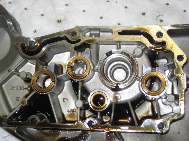 |  |
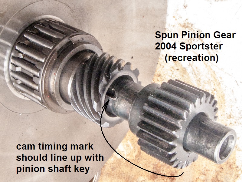
Possible Causes of a Spun Pinion Shaft Gear
There is a bronze oil pump gear available which is considered an upgrade but that won't stop the key from shearing.
Read more about the oil pump drive gear failure and upgrade here in the Sportsterpedia.
- Loose pinion shaft nut.
- When installing the pinion nut, use Loctite red per the manual, and torque it to 70ft-lbs. 14)
It's pretty rare to have the gear fail in a stock Sportster. You typically only run into this issue after hop-up work.
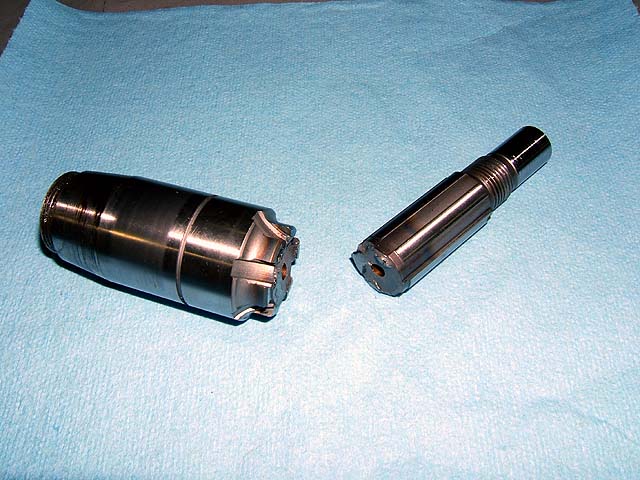
The factory torque spec is 35-45 ft/lbs. which is too little torque for upgraded engines and often results in a sheared pinion key. - Per HD Tech Tip #19, the “T” key simply aligns the pinion shaft to the mark on the pinion gear for timing the cams. 15)
With the introduction of the one piece, right hand flywheel, the pinion shaft no longer has a taper.
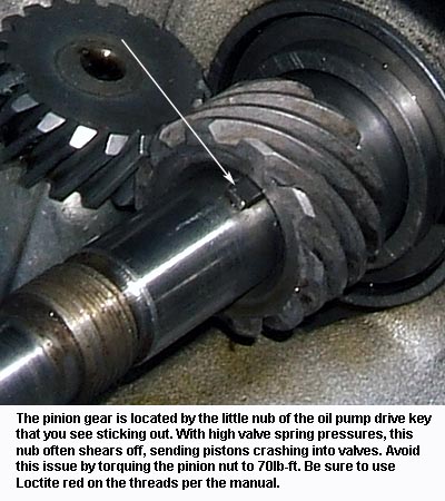
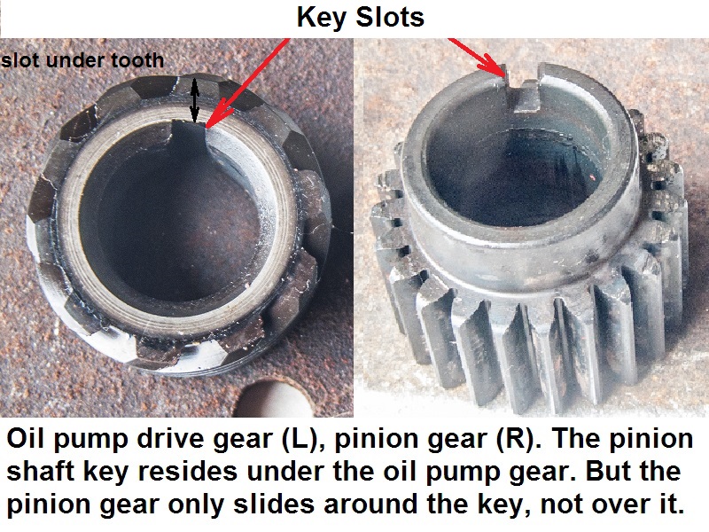
Instead the oil pump drive gear and the pinion gear depend on clamp load to remain in position. - In the pics below, the little nub of the key that protrudes from under the oil pump gear is the only portion of the key that engages the pinion gear. 16)
That's why it shears so easily if the nut is loose. There just ain't much holding it besides the clamp force of the nut.
The clamp force from the nut holds the pump gear on, not the key.
- Using heavy Valve Springs.
- Breaking the key is a very common issue particularly when heavy valve springs are used.
The force from the springs transfers thru the cams to the pinion gear and puts extra pressure on the pinion key.
And that force may be enough to break the key allowing the pinion gear to move.
The fix is Loctite red and 70ft-lbs instead of the factory specified 35-45ft-lbs. You won't have this issue again. 17)
The higher clamp force is needed to overcome the pressure of heavy springs.
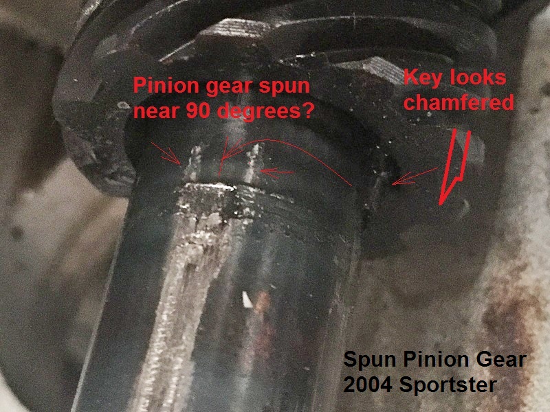
| Pinion key location 18) | Condition of key after gear spins 19) | Pinion gear spun (app 90°), stopped and still turned the cams from new location 20) |
 | 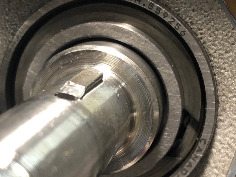 |  |
- Spotting a spun pinion gear with the cam cover off.
- There is a keyway (slot) cut the width of the oil pump gear (underneath it, under one of it's teeth).
There is also a short slot (keyway) cut into the inner side of the pinion gear (not under it) and the slots in the two gears line up.
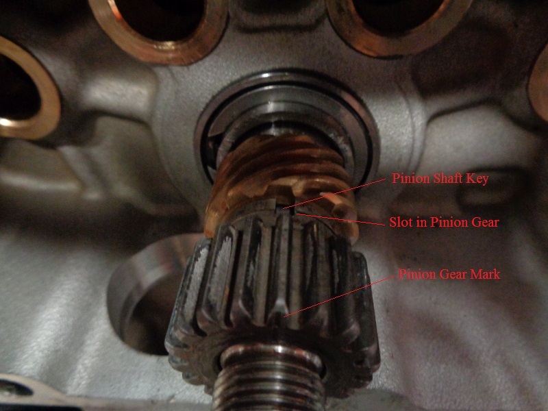
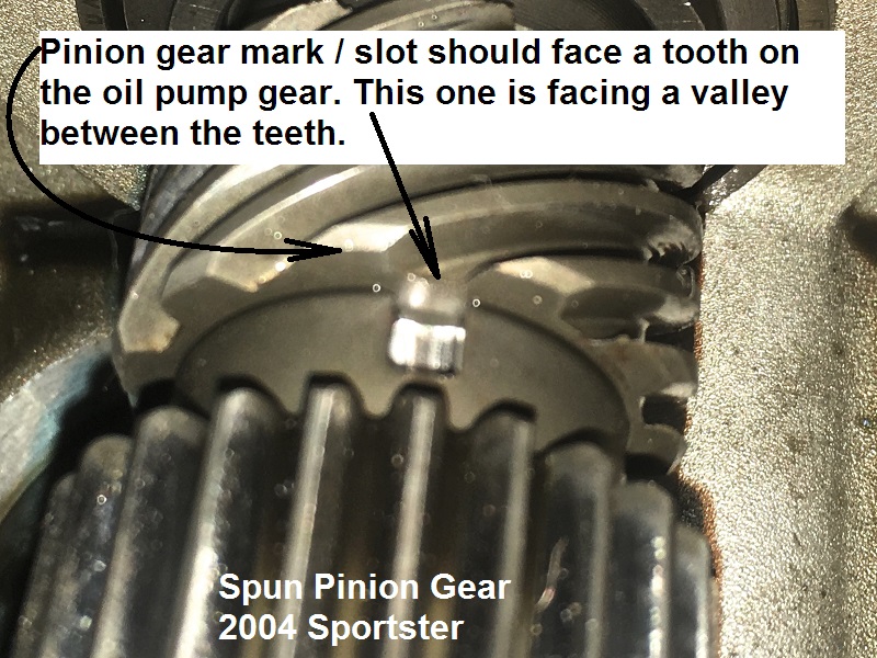
The timing mark on the pinion gear is lined up with the slots. So the timing mark on the pinion gear should line up with a tooth on the face of the oil pump gear.
If you hear noises or suspect damage in the gearcase, pull the cam cover and look a straight line back from the pinion gear's timing mark to oil pump drive gear.
If the pinion gear slot is facing a valley (between two teeth) on the pump gear, the pinion key (at least the part that holds the pinion gear) has sheared.
And the pinion gear has turned to some degree out of time with the crankshaft. - This also brings concerns of bent pushrods from the cams getting out of time due to the spun pinion gear and a valve hitting a piston.
| 1988-up oil pump drive gear / pinion gear keyways. 21) |
 |
Affects of a Spun Pinion Shaft Gear
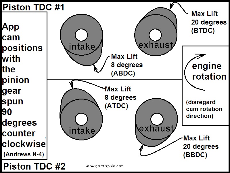
The drawing below shows 2 valve trains at the same time on the same cylinder using Andrews N-4 cams. 24)
It represents cam timing/valve opening and closing times in respect to piston position.
The blue directional arrow represents engine rotation direction. The orange and green lines represent cam/valve lift and / or position at the specific crank locations in degrees.
So you are seeing the piston movement in degrees and the position in degrees of each cam lobe. Max lift is exactly in the middle of each opening and closing times of each valve.
You'll see in this drawing that normally, at TDC and BDC, max lift on the cams will not happen at either location.

Now with the pinion gear rotated 90º counterclockwise, the same exact opening and closing times happens in the valve train.
Cam timing remained the same respectively but they just happen 90º later than they were originally.
A notation was made on the drawing to mark the approximate point of max lift for each valve.
There is more to max lift than just the valve opening. But this is for example only to illustrate where the highest lift might occur during TDC.
As you can now see, max lift will occur at or near TDC. TDC happens twice per 1 revolution of the cam/valve opening.
So in this example, the degree wheel below turns 2 full revs to make 1 full rev of each cam, thus valve train.
In the drawing below;
The intake cam lobe center (point of max lift) is now resting at app. 8º after BDC.
On the next TDC event (360º of crank movement), max lift (180º of cam movement) on the intake valve will occur at 8º after TDC.
Next TDC event, max lift will be back at 8º after BDC.
The exhaust cam lobe center (point of max lift) is resting at app. 20º before TDC.
On the next TDC event (360º of crank movement), max lift (180º of cam movement) on the exhaust valve will be app 20º before BDC.
Next TDC event, max lift will be back at 20º before TDC.
So in this example, the intake valve should take the first hit before the exhaust valve would due to the proximity to the piston during rotation.
Note: all you have to do is turn this drawing upside down, change BDC to TDC and you'll see that the intake valve is at or near full extension when the next TDC rolled around.

The drawing below is in conjunction with the drawing above to visualize cam lobe positions.
Disregard cam rotation direction as the drawing is showing cam lift / valve opening.
This is simply to show which direction the cam lobes face in the spun pinion gear scenario.
Crankshaft Out of True
See Measuring Pinion Shaft Runout in the REF section of the Sportsterpedia.
- Safe installation of the pinion gear requires a pinion locking tool as well. 26)
If you hold the crank by any other method while removing or installing the pinion nut, you apply torque through the crank from one side to the other.
And they're not designed to hold much torque that way, you risk knocking it out of true.
Here's the worst symptom of an out-of-true crank. The pinion shaft snapped. 27)
This particular one happened at roughly 180mph. I had qualified the bike at 207 and change, and was on my backup pass.
Everything was going smooth, I had it wound out in 4th, I eased off the throttle, clicked it into 5th, eased out the clutch and rolled back into it and …
Nothing. The fire had completely gone out.
I said a bad word. I pulled off the course and noticed the timing rotor wasn't turning (it's exposed on this bike).
One time several years ago, HAMMER Dan called me from a race he was at, out east somewhere.
He was all in a panic because it was Friday afternoon and he was sure he had bent a valve and wanted me to overnight him some valves with Saturday delivery.
After chatting with him a bit I convinced him to look a little deeper before we started jumping through hoops … he got a rocker box top off and sure enough, nothing was moving.
He had done the same thing.
Crankshaft / Rod Bearing Failure
- Crank Failure.
- Crank failure is usually always seen from the front (center) rod bearings that go first. That includes aftermarket cranks as well. 29)
There have been more 04 and 05 failures than we ever saw with the 03s and older.
Most of the 04 and 05s also have less miles than your typical 03 and under does too so it tells me that the new cranks have much worse bearings.
15)
HD Tech Tip #19 dated June 1990
16)
aswracing of the XLFORUM
20)
photo by npaisnel of the XLFORUM, edited by Hippysmack https://www.xlforum.net/forum/sportster-motorcycle-forum/sportster-motorcycle-motor-engine/sportster-motorcycle-engine-conversions/200486-crank-failure-and-killed-my-1275-hammer-build/page23?t=2077485&page=23
21)
photo by npaisnel of the XLFORUM, labeled by Hippysmack https://www.xlforum.net/forum/sportster-motorcycle-forum/sportster-motorcycle-motor-engine/sportster-motorcycle-engine-conversions/200486-crank-failure-and-killed-my-1275-hammer-build/page26?t=2077485&page=26
22)
photo by Hippysmack
23)
photos by npaisnel of the XLFORUM, labeled by Hippysmack https://www.xlforum.net/forum/sportster-motorcycle-forum/sportster-motorcycle-motor-engine/sportster-motorcycle-engine-conversions/200486-crank-failure-and-killed-my-1275-hammer-build/page24?t=2077485&page=24
25)
Drawing by Hippysmack
29)
NRHS Sales of the XLFORUM