Table of Contents
This is an old revision of the document!

REF: Service Procedures 11
1991-2003 5 Speed Transmission Removal / Inspection / Installation
This section is not meant to be a replacement to the FSM.
It is meant as a compliment to the FSM with added information with pics that are not in the manual.
Always buy an Factory Service Manual AND a Factory Parts Catalog to help you along your maintenance path.
The Haynes and Clymer brand service manuals for the most part will suffice and they generally have more pics than the HD Service manual.
But the HD manuals will be the most accurate.
All in all, there are discrepancies in all of them including the HD parts and service manuals though.
Sub-Documents
Transmission Removal / Installation
Also reference the sub documents above for a more in-depth look at the shifting mechanism and associated issues with it.
Click on any pic below to enlarge:
Going through all these steps will familiarize you with your transmission both mentally and physically.
Once removed, you should lay the tranny horizontally on a bench and physically run through the gears.
Make sure there is no binding and that movements are free and smooth. It will have some play since it's not installed.
Move the shift forks with your hands to make the gears move and run through and back.
Later on, you'll feel the gear action and you'll know how it sounds and feels when actuated by itself with no load.
This may help you diagnose later when things will not shift properly.
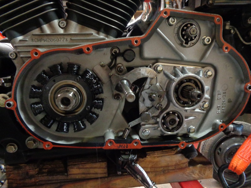
- Before removing anything after the primary cover comes off, check all parts for scoring, metal to metal contact or bits of metal or debris in the case.
Remove the Primary Cover
Diagnosis begins before, during and after a teardown.
Before the primary cover comes off, remove the primary drain plug and check the magnetic end for excess debris.
This will give you an idea whether or not there is imminent wear you may need to look for once inside the primary.
A small amount of mush is normal as the metal to metal contact will accumulate metal mush over time.
But it should not be in the form of spurs or shards on the magnetic drain plug.
Also check the color of the primary oil.
It'll smell like gear oil which is normal but it should not be multicolored or full of metal grains.
The shifter arm will most likely have some light scoring from contact with the back of the clutch basket.
And the starter ring gear teeth have a red tent and scorings.
See the link “What Causes the 1991-2003 Shift Arm to Scrub the Starter Gear” in the sub documents at the top of the page.
The detent arm below shows signs on scoring and they are deep across the arm in one place.
| 1998 1200S Primary 1) |
Removing the Primary Drive
See also Replacing Stator Magnets in the tools section of the Sportsterpedia.
Note:
Unless noted otherwise, the engine below is a 98 XL1200S that has been upgraded to 1250 with a Buell XB crankshaft and respective engine sprocket.
Normally when loosening or tightening these nuts, you will need to lock the hub & sprocket - Do not wedge the chain.
You can buy a primary locking tool (bar) or use a closed 4“ BRASS hinge as a wedge. Place the wedge so as not to put pressure on the shifter shaft
There are also several 4 and 5 speed primary locking tool examples in the tool section.
A closed 4” BRASS hinge also works well to lock the sprockets and then you can use a pull bar and sockets / socket wrench.
The threads should have previously been assembled with red Loctite.
Using a propane torch (on the nut or bolt only) will heat up and melt / soften the Loctite somewhat to make removal easier.
Remove both fasteners holding them on before attempting to remove either.
Big socket wrenches or pullbars give you a lot more leverage to make removing the fasteners less strenuous.
Note:
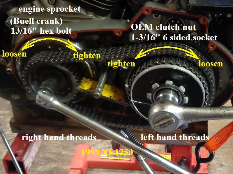
The engine sprocket has right hand threads (lefty loosy-righty tighty)
The clutch basket has left hand threads (lefty tighty-righty loosy)
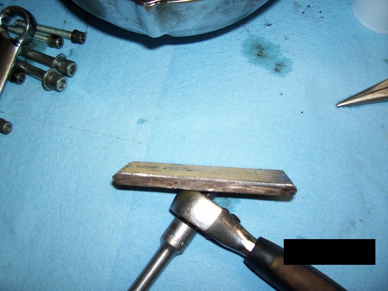
| This tool made from 5/16“ scrap steel to lock the sprockets (app 4-1/4” x 1-1/2“ with beveled the edges). 2) | |
 | |
| XL1200S 3) | XL1250S with Buell XB crankshaft 4) | |
| Engine and clutch sprockets are removed at the same time and thread directions are the same. | ||
 |  |
|
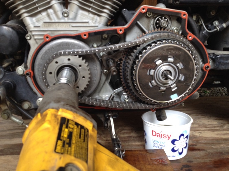
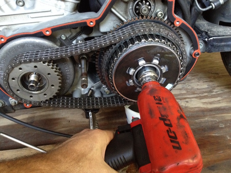
A reversible impact wrench has been used successful in removing both the engine sprocket and the clutch basket nut.
However, it's not recommended to use for installing either sprocket. A torque wrench is needed to get the proper clamp foce on the fasteners.
Whichever way you remove them, use regular six-sided sockets.
They are less likely to slip and round off the edges of the nuts. Impact-type sockets may be too thick to fit.
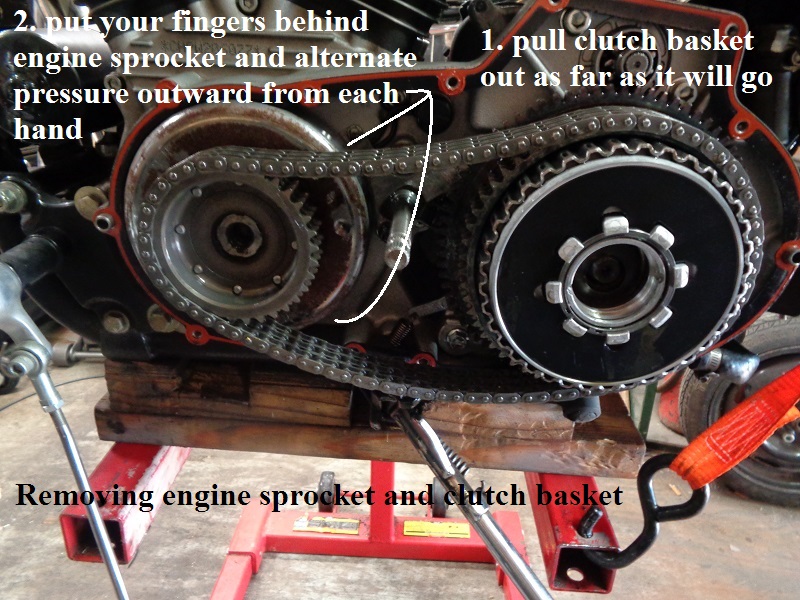
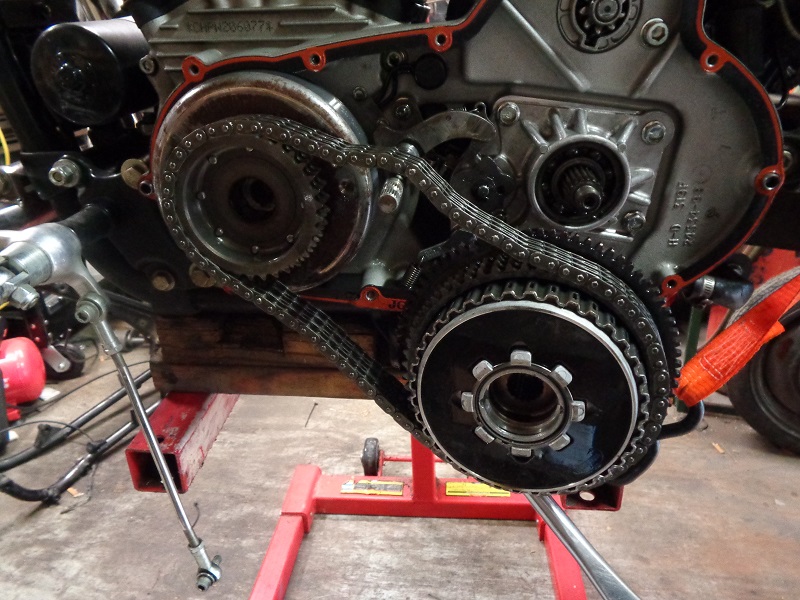
The engine sprocket and clutch hub should be removed as one unit.
Both have to come out together to some point since the chain will tighten and neither will budge at that point.
Once they are both moved out far enough, you may be able to get one or the other to come off without the other.
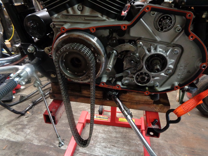
Once the sprocket and clutch basket is removed, you can gain access to the mounting screws for the stator.
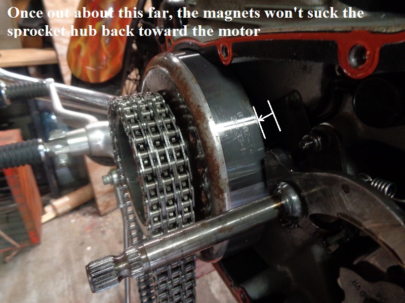
You'd think both should slide off at this point.
However, the magnets on the engine sprocket are very strong and will keep a good amount of pressure toward the engine until it's moved out so far.
Pull the clutch basket out as far as possible and then maneuver your fingers both hands under the engine sprocket.
Rock it side to side while pulling outward.
Slowly you can rock it out enough to get your fingers under it to move it out far enough to release the force generated by the magnets.
If the chain gets tight, move the clutch basket out some more and go back to the sprocket.
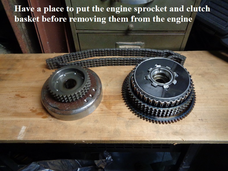
DO NOT DROP THE ENGINE SPROCKET. The magnets can crack or break off and that's a different problem.
However they come off is fine as long as they are not dropped.

Make sure you already have a place to put them and a clear walking path before removing them from the engine.
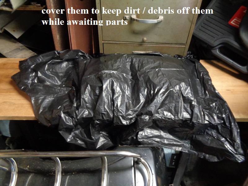
Cover them to keep dirt / debris off them until they are ready to go back on.
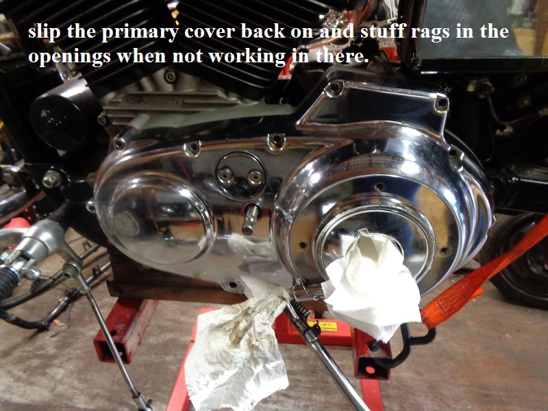
Slip the primary cover back on and stuff rags in the openings when not working inside the engine to help keep out dirt / debris.
| This is why you should not beat on the engine sprocket to loosen it. Too easy to break the magnets behind it. 15) |
|
Disassembly
You can do this with the tranny laying on a bench but it's easier to prop the shaft ends up so you can lift gears and use both hands on retainers and such.
You can use soft jaws in a bench vise to hold the assembly.
You can also cut the outer race off the old main and countershaft bearings with a Dremel to use the inner races as a press block for new bearings.
The main inner race also doubles as a stand for the mainshaft to keep the threads safe in a vise.
![]() |
|![]() |
|
Inspection and Associated Wear
Once the tranny is out and before disassembly, you can test for smooth movement of the gears, forks and bearings.
You can set it on a bench and prop it up so you can visually inspect all parts for damage or wear and run through the gears by hand.
It will be flimsy, not installed, since the rear of the shafts are normally supported by the right case.
But you can carefully position it to check gear movement.
![]() |
|![]() |
|
Shift Forks
The shift forks will probably have some side wear marks (which may not be a problem but more of a symptom).
Check the inside contact surfaces for scoring / wear on the edges.
The ones below all have a small amount of wear with the middle one having a wave of wear on the inside surface where it should contact the gears.
Worn contact area equals more space between it and the gears than intended which adds to slop.
The used fork ends below were .202” on both inside and outside edges.
Check the fork ID's to make sure they are all the same. The ones below are all 1.248“.
Excess clearance in the fork to shift drum bore contributes to binding of fork movement.
Check the holes in the side of each fork where the metal dowel pin slides in. The holes should be round.
The ones below were more oval shaped from side wear / mis-movement and two of the solid dowel pins measured .579” with another measuring .576“.
These oval shaped holes contribute to the binding of shift fork movement and roughing up the sides of the pin channels in the shift drum.
It's best to replace forks with wallowed out pin holes.
Countershaft / Mainshaft
The thrust washers used on the shafts most likely won't all be the same thickness (even when new due to quality control).
The used ones below varied from .0675” to .068“. New ones are generally around .069”.
You can also put the mainshaft, countershaft and shift drum between centers and check for warp-age or roll them on a thick piece of (clean) glass.
Shift Drum
You may find abrasions on the outside edge of the shift drum channels where the solid pins ride.
These may have come from worn forks or pins that direct the forks.
If they are not too rough and don't have any gouges that would hinder the pins from moving, you can polish the roughness out.
Using something like 600 grit wet/dry sandpaper and steel wool you may be able to salvage the drum.
Check the raised area in the center of each dowel pin channel for damage or wear.
The raised bump running the channel for the dowel pins provide a surface for the pins to ride on.
Also oiling underneath the pins happens in the valley below created by the raised runner.
If any of these conditions exist and can not be repaired, the drum must be replaced.
Rough edges on the channels can hang up the pins and hinder shift fork movement causing missed shifts / damaged gears.
An uneven pin runner will not allow proper oiling and will also hinder shift fork movement.
You can test pin movement by sliding a dowel pin down the channels by hand (it as in normal operation) and see if it runs smooth or binds / catches during travel.
It's not on the inside but just on the outer edge of the slot.
In the pics below, 3rd gear pin position on the drum suffered from a not entirely gone but erosive raised up area in the channel.
Measure the shift drum pins. They should all be the same length from the drum face (installed height .326“ - .334”).
However, it is common for some or all of them to pull out of the drum a little.
Some (most) just knock the pins back in the drum with a hammer. And some pull add Loctite to the side of the pins before knocking them back in.
If you pull a pin out to add Loctite, it'd be best to use it on the sides of the pin (not bottom or not in the drum holes).
Then Loctite should remain in the nooks and crannies between the pin and hole but not in the hole center to block the pin from going home.
If it gets in the hole center, it will hydro-lock the pin and not let it go all the way home.
Keep in mind that hot Loctite may either let go or slide so that may either stop or slow down a moving pin .
See also What Causes the 1991-2003 Shift Drum Pins to Walk Out of the Drum in the Sportsterpedia.
Trap Door
Check the trap door with a straightedge to insure there is no warp-age.
Shifter Detent Plate
You may find the shifter detent plate to be leaning at an angle with scoring on the outside face.
This is a common condition due to the drum pins walking out of the drum at different times and lengths.
The detent plate below was found to be leaning and none of the pins were the same length out of the drum.
Also check the depth of the holes the back of the plate that go onto the shift drum pins. They should all be the same depth.
When the pins are forced out of the drum by the shift pawl, the pressure can make the holes too deep making proper re-alignment impossible.
See also What Causes the 1991-2003 Shifter Detent Plate to Lean in the Sportsterpedia.
If you haven't already, buy the updated shifter detent plate (33656-90A).
The original detent plate (33656-90 ) which is now obsolete, is made of an aluminum alloy and has longer (slower) drop points for the detent arm.
The -90A is a smaller diameter plate with more radical shift curves and a more positive ‘lock in’ with sharper drops than the old one.
See also 1991-2003 Shifter Detent Plate Retaining Ring Alternatives in the Sportsterpedia.
Shifter Shaft
The shifter shaft will flop around with the primary cover and that is normal due to the way it is designed.
The primary cover only gives the shaft a place to rest (does not make the shaft rigid during operation).
There are plenty of ways the shaft can turn, twist and move around during operation. The clearances in the parts allow this to happen by design.
But there are times when some of the parts wear and add extra clearances which makes shifting more difficult.
See also Why There is So Much Slop in the 1991-2003 Shifter Shaft in the Sportsterpedia for more in depth explanation of the conditions below.
| This clearance around the spring coil gives the shift arm's willingness to lean. 16) |
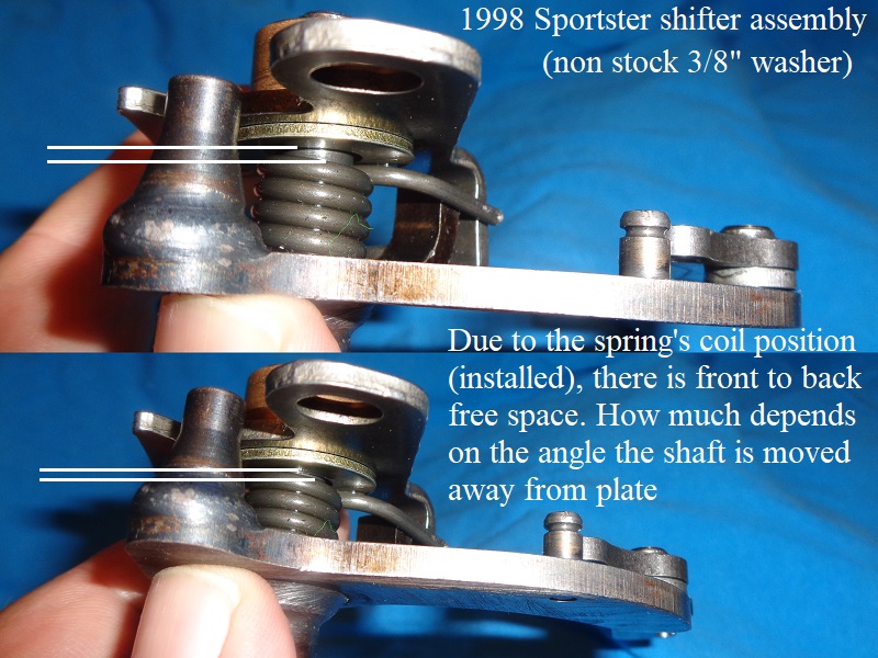 |
The mounting plate (shift shaft to case) does not keep the shaft rigid when holding it by hand mostly due to the coil spring between it and the shaft.
The plate pulls up or down tension against the healthy spring that's wrapped around the shift shaft and returns the shaft to “near” center.
While this is normal, the spring has 2 fingers on the end controlling up and down play between the mounting plate and the shaft.
The distance between the fingers can extend over time which allows back and forth wiggle of the shift pedal before a shift is actually initiated.
You can use some pliers to squeeze those fingers together (closer to their grab points on the shifter assembly).
Soon after in operation, the spring will still widen a little from where you compressed it, but it should be a small amount.
So if you have more .010“ clearance between the spring and plate hook, you can shorten that clearance to get a little less slop there.
The spring below was adjusted to “0” clearance.
However, after a couple thousand miles, the spring arms did spread out a little (app .009”) yet doesn't seem to pose an issue.
| |
There is a bushing behind the shift pawl and one side of it has a flush cut end with the other side having a rounded end.
This is by design to allow the pawl to have side movement to line up with the pins by gravity before grabbing them.
So there is a bit of slop there but that is normal.
However, that bushing will wear down and a new one should leave a little less slop there.
The more slop there, the farther the pawl will lean but pawl leans by design to a degree.
The more side play after the designed amount may allow the pawl to pull a pin out farther (if a pin is in the condition to walk out anyway).
And you may gain several thousandths of meat back with a new spacer.
| Shift Pawl Bushing 17) |
The inner shaft bushing is not a press fit into it's primary case bore but a loose fit and will be easy to slide in and out of the bore.
Some have tossed ideas of using a Loctite sealer around the bushing or pinning the bushing in place.
But the primary cover sets the shaft's vertical and horizontal position and it's not possible to eyeball what that position will be.
Unless you can guess correctly where the resting position of the shaft will be, constraining the bushing can lead to binding the shaft and bushing wear later.
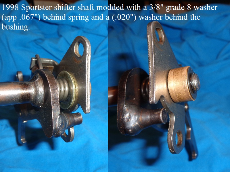
| Inner shaft bushing clearance. 18) | |
There is a clearance between the inner shaft bushing and the mounting plate due to the coil on the shaft spring.
You may not get any free horizontal play thru the bushing / shaft movement (IF) you don't let the coil space on the spring collapse in your hand.
But you may get .050“ or more play there if you push the plate over the free space near the coil.
Worn spacers can add to that clearance. The amount of free clearance there contributes to excess shaft axial movement and shaft slop.
You can use a thicker washer between the plate and spring to beef up that connection and leave a little less slop there.
The shaft will “flex” back a little better with a thicker washer and a thin one on the end.
 |
Clutch Basket / Starter Ring Gear
The back side of the teeth on the starter ring gear may have some wear where they rub against the shifter shaft arm or detent plate.
This shouldn't hurt the ring gear though.
The rough edges on the starter sprocket can smoothed down with sandpaper or a wire brush if desired.
See also What Causes the 1991-2003 Shift Arm to Scrub the Starter Gear in the Sportsterpedia.
The starter ring gear is pressed onto the rear of the clutch basket and has been known to slide rearward away from it.
This may never happen as it doesn't happen everyday, but always keep that in mind when it's found that the shift arm is constantly scrubbing the ring gear.
There are plenty of loose clearances in the shift chain that could cause contact but most of these involve only momentary contact.
But there should be clearance between the shift arm and starter ring gear if you lift the shift shaft to the upper extreme.
A measurement was taken between the arm and gear with a feeler gauge at .043” (1.0922mm) without any scrubbing noticed (shaft lifted up by hand w/ cover off).
This dim is just a dirty one and results will vary. But the point of that measurement is there is that there will be some clearance between the two.
If the arm stays against the ring gear when the shaft is lifted, check the starter ring gear for breakage or slippage.

Transmission Gears
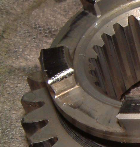
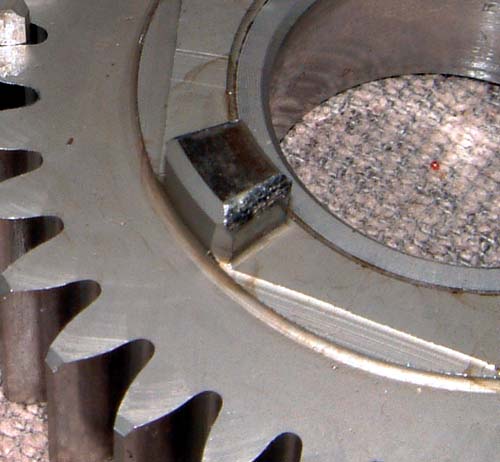
Check for worn dogs:
The gear dogs can wear on the sides. 22)
They will sometimes become rounded off instead of being flat on the edges.
This can cause the gears to not sync 100% and pop out of gear.
| Worn dogs 23) | |
 |  |
Countershaft Gear Pics
| Countershaft 5th - 25 teeth | |
| Countershaft 4th - 26 teeth | |
| Countershaft 3rd – 29 teeth | |
| Countershaft 2nd – 34 teeth | |
| Countershaft 1st – 32 teeth | |
Mainshaft Gear Pics
| Mainshaft 4th – 32 teeth | |
| Mainshaft 3th – 34 teeth | |
| Mainshaft 2th – 29 teeth | |
| Mainshaft 1st – 20 teeth | |