Table of Contents
This is an old revision of the document!

EVO: Electrical System
FUSES, RELAYS, CHARGING SYSTEM
Be sure to review the basic Electrical Concepts in the Reference Section, especially wire gauging.
The following quotation makes the point that fuses are often slow to react to overcurrent situations. It is critical to replace rated fuses with the same rating in order to properly protect the circuits.
First, fuse ratings can be a bit misleading. A 10A ATO (automotive) fuse will conduct 11 amps for 100 hours minimum. At 13.5 Amps a 10A ATO fuse can take as long as 10 minutes to blow. It is not like once you draw 10 amps “poof” the fuse is gone. (From FUSE SIZING PRIMER located at http://www.powerlet.com/learningCenter/fuseSizing)
Fuses/Circuit Breakers
(1984L-1990)
- All 1986 to 1990 models have 4 circuit breakers mounted on the front side of the rear fender under the seat. 1)
- Circuit Breakers (CB) - Under Seat - Automatically Resettable - Ring Lugs for wiring
- 30A - Main Circuit Breaker
- Keyswitch
- 'Ignition' position (White Wire) runs to Ignition & Accessories CBs
- 'Lights' position (Green Wire) runs to Lights CB
- Both Keyswitch positions feed all CBs because of jumper between Ig & L at Keyswitch
- Circuit Breaker Ratings
- 15A - Lights CB
- 15A - Ignition CB
- 15A - Accessories CB
(1991-1993)
- All 1991 to 1993 models have 4 circuit breakers mounted on the front side of the rear fender under the seat. 2)
- Circuit Breakers (CB) - Under Seat - Automatically Resettable - Ring Lugs for wiring
- 30A - Main Circuit Breaker
- Keyswitch
- 'Ignition' position (White Wire) runs to Ignition & Accessories CBs
- 'Lights' position (Green Wire) runs to Lights CB
- Both Keyswitch positions feed all CBs because of jumper between Ig & L at Keyswitch and buss bar at CBs
- The 4-way Flashers are activated from the 'Accessory' position by pressing both turn signal switches at the same time - Flashers will operate this way until the battery is dead or the keyswitch is turned off
- Circuit Breaker Ratings
- 15A - Lights CB
- 15A - Ignition CB
- 15A - Accessories CB
(1994-1997)
- All 1994 to 1997 models have 5 circuit breakers mounted under the seat. Ignition, instruments, lights and accessories are mounted on the circuit breaker block installed in the electrical bracket under the seat. The main circuit breaker is mounted on the electrical bracket on the right side of the circuit breaker block.3)
- Circuit Breakers (CB) - Automatically Resettable
- 50A - Main Circuit Breaker (1994-1996)
- 30A - Main Circuit Breaker (1997)
- Keyswitch
- 'Accessory' position allows 4-way Flasher without other Lights active
- 'Accessory' position (Green Wire) runs to Accessories CB (also active with Ignition position)
- 'Ignition' position (White Wire) runs to Ignition, Instruments and Lights CBs
- The 4-way Flashers are activated from the 'Accessory' position by pressing both turn signal switches at the same time - Flashers will operate this way until the battery is dead or the keyswitch is turned off
- Circuit Breaker Ratings
- 15A - Ignition CB
- 10A - Instruments CB
- 10A - Lights CB
- 15A - AccessoriesCB
(1998-2003)
- These models have a Main Circuit Breaker, 4 Fuses, the Starter Relay and the Data Link Connector (1200S Only) located under left-side triangle cover to rear of battery.
- Fuses - Socketed and individually insertable
- 30A - Main Circuit Breaker
- Keyswitch
- 'Accessory' position allows 4-way Flasher without other Lights active
- 'Accessory' position (Red/Green Wire) runs to Accessories Fuse (also active with Ignition position)
- 'Ignition' position (Red/Black Wire) runs to Ignition, Instruments and Lights Fuses
- The 4-way Flashers are activated from the 'Accessory' position by pressing both turn signal switches at the same time - Flashers will operate this way until the battery is dead or the keyswitch is turned off
- Fuse Ratings
- 15A - Ignition Fuse
- 15A - Instruments Fuse
- 15A - Lights Fuse
- 15A - Accessories Fuse
(2004-2006)
- Fuses - Socketed and individually insertable - Fuse Panel under left side panel behind battery
- 30A - MaxiFuse - Socketed and insertable - At Battery
- Keyswitch
- 'Accessory' position (Red/Green Wire) also active in Ignition position
- 'Ignition' position (Red/Black Wire)
- The 4-way Flashers are activated from the 'Ignition' position (with the RUN switch on) by pressing both turn signal switches at the same time - The key can then be turned off & removed - Flashers will operate for up to 2 hours, then automatically shutdown
- Fuse Ratings
- 15A - Accessories Fuse (KeySw-Red/Green)
- 15A - Battery Fuse (Red wire from MaxiFuse direct)
- 15A - Lights Fuse (KeySw-Red/Black)
- 15A - Ignition Fuse (KeySw-Red/Black)
- 15A - Instruments Fuse (KeySw-Red/Black)
- 15A - Spare Socket (Unconnected)
(2007-2009)
- Fuses - Socketed and individually insertable - Fuse Panel
- 30A - MaxiFuse - Socketed and insertable - By Battery
- Keyswitch
- 'Accessory' position (Red/Gray Wire) also active in Ignition position
- 'Ignition' position (Black/Red Wire)
- The 4-way Flashers are activated from the 'Ignition' position (with the RUN switch on) by pressing both turn signal switches at the same time - The key can then be turned off & removed - Flashers will operate for up to 2 hours, then automatically shutdown
- Fuse Ratings
- 15A - ECM Fuse (Red wire from MaxiFuse direct)
- 15A - Fuel Pump Fuse (Yellow/Green wire from System Relay)
- 15A - Spare Socket - Unconnected
- 15A - Ignition Fuse (KeySw-Black/Red)
- 15A - Instruments Fuse (KeySw-Black/Red)
- 15A - Spare Socket - Unconnected
- 15A - Accessories Fuse (KeySw-Red/Gray)
- 15A - Battery Fuse (Red wire from MaxiFuse direct)
- 15A - Lights Fuse (KeySw-Black/Red)
- 15A – P&A Ignition Fuse (KeySw-Black/Red)
- 15A - Spare Socket (Unconnected)
- … - Open Socket
- NOTE: These model years have a significant history of corrosion and gunk collecting in the fuse/relay tray causing low-grade shorts and erratic electrical operation - This is especially problematic if the bike is left outside or operated in the rain. It's a good idea to check & thoroughly clean this tray at least every year (or 4 to 6 months if parked outside).
(2010-2013)
- Fuses - Socketed and individually insertable - Fuse Panel
- 30A - MaxiFuse - Socketed and insertable - By Battery
- Keyswitch
- 'Accessory' position (Red/Gray Wire) also active in Ignition position
- 'Ignition' position (Red/Black Wire)
- The 4-way Flashers are activated from the 'Ignition' position (with the RUN switch on) by pressing both turn signal switches at the same time - The key can then be turned off & removed - Flashers will operate for up to 2 hours, then automatically shutdown
- Fuse Ratings
- 15A - Ignition Fuse (KeySw-Red/Black)
- 15A - Lights Fuse (KeySw-Red/Black)
- 15A - Accessories Fuse (KeySw-Red/Gray)
- 15A - ECM Fuse (Red wire from MaxiFuse direct)
- 15A - Battery Fuse (Red wire from MaxiFuse direct)
- 15A - Spare Socket (Unconnected)
(2014-????)
- 2014 - First Year of BCM (Body Control Module) for direct electrical control (minimizes fuses & eliminates relays)
- Fuses - Socketed and individually insertable - All fuses on Fuse Panel Cable (Near Battery)
- 40A - MaxiFuse - Socketed and insertable
- Keyswitch - Multilevel voltages using only two wires - Black/Green is Ground - Blue/White is signal to BCM
- 'Accessory' position provides a 'semi-Hi' signal on the Blue/White wire (using 800 ohms to ground)
- 'Ignition' position provides a 'Lo' signal on the Blue/White wire (using 200 ohms to ground)
- 'Off' position provides 'no load Hi' signal on the Blue/White wire (using no connection to ground)
- The 4-way Flashers are activated from the 'Ignition' position (with the RUN switch on) by pressing the triangle switch above the starter switch - The key can then be turned off & removed - Flashers will operate for up to 2 hours, then automatically shutdown
- Fuse Ratings
- 15A - Battery Fuse - ATO-type
- 15A - P&A Fuse - ATO-type
Relays
(Be sure to see the note at the end of this section regarding diodes in relays)
(1975-1979)
- Starter Relay is auto type, two-bolt frame mount, ring lug for wire mounting
- HD 71463-73A
- NAPA MPE ST404SB
- NAPA ECH ST404
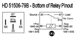
(1980-1992 & Early 1993)
- Starter Relay is single-bolt lug mount, connectorized
- Under the seat, on frame by the circuit breakers
- HD 31506-79B
- NAPA ECH MC23010
- Standard MC-RLY2
- Tyco V23234C1001X008
- Bosch 0332019151

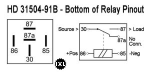
(1994-2003 & Late 1993)
- Starter Relay is single-bolt lug mount, connectorized
- L93-97 - under the seat, on the circuit breakers mounting frame
- 98-03 - under left-side triangle cover to rear of battery
- HD 31504-91B
- NAPA ECH MC23013
- Standard MC-RLY4

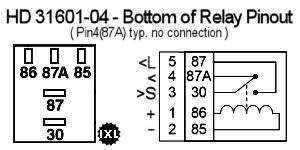
(2004-2009)
- Starter Relay in 2004 became plug-in on Fuse Panel
- System Relay was added in 2007 as plug-in on Fuse Panel
- Both Relays are interchangeable (especially for diagnostics)
- HD 31601-04
- Possible Alternatives:
- NAPA ECH AR614
- Standard MC-RLY8
- Borg Warner R3154
- Niehoff RL 35381
- Gp Sorenson 41-5154
- OMRON G8H-UA-007401
- NOTE: The 2007-2009 model years have a significant history of corrosion and gunk collecting in the fuse/relay tray causing low-grade shorts and erratic electrical operation - This is especially problematic if the bike is left outside or operated in the rain. It's a good idea to check & thoroughly clean this tray at least every year (or 4 to 6 months if parked outside).

(2010-2013)
- Both Starter & System Relays are interchangeable (especially for diagnostics)
- HD 31586-07
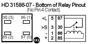
- Possible Alternatives:
- Standard MC-RLY9
- (Superceded from: 31579-04)

(2014-on)
- Body Control Module (BCM) expanded capability - Eliminated relays (minimized fuses)
- 69992-12B BCM w/o Security
- 69994-12B BCM w/Security
NOTE: Polarity & Diodes
(This document may be of interest: http://www.autoshop101.com/forms/hweb2.pdf)
CHARGING SYSTEM
Alternator Design
Basic Alternator (Stator) Test
Checking for Shorts
…Pull the connector between the Stator & Regulator (2-pin connector near the regulator)
1) Measure Resistance between the two Stator Pins (should be 0.2 - 0.4 Ohms)
2) Measure Resistance from each Stator Pin to Ground (should be infinite Ohms)
Checking for Sufficient Voltage Production
With the Regulator still unplugged from the Stator:
…Start Engine & run at approximately 2000 RPMs (Set meter on AC Volts - 100v Scale)
3) Measure AC Volts produced between the two Stator Pins (should be 35-55 AC volts or more)
Shut down the engine - Reconnect the Regulator - (Be sure to do voltage & ground checks - Click Here)
Voltage Regulator