Table of Contents
This is an old revision of the document!
EVO: Engine Control
STARTER & SOLENOID ASSEMBLY
Starter & Solenoid Function
The starter system consists of the following components: Starter Switch, Starter Relay, Starter Solenoid & Starter Motor, the last two being combined into a unit. The starter power rating is 1.2kW. 1)
The Starter Switch is activated from the right handlebar switch housing. It is fed power when the Run/Stop switch is in the RUN position. When pressed, the Starter Switch (button) supplies power to the Starter Relay, which is located near the fuses. When activated, the Starter Relay will supply, thru it's controlled contacts, power to the Starter Solenoid. Starter Relays are subject to corrosion and oxidation. Since they are relatively inexpensive, the Starter Relay should be replaced every 5-years or sooner if there is any question of its operational functionality.
The Starter Solenoid has three connections and performs two functions.
One connection to the solenoid is from the starter relay, which activates both of its functions. When activated, the solenoid pull-in wiring pulls the solenoid plunger forward - which, thereby, pulls the starter pinion gear into engagement with the ring gear on the clutch housing in the primary.
The second function that the solenoid performs is to close the high-amperage contacts (in essence, a switch) between the battery and the starter motor. This occurs as the plunger is moving forward. Initially, the pull-in windings will move the plunger forward and then the hold-in windings will keep a solid contact there until you release the starter switch button.
The high-amperage contacts will activate the starter motor. Typical starter current draw will range from 160 to 200 amps. If starter current draw exceeds 250 amps, the problem may be in the starter or starter drive. Remove starter for further tests.
Off Bike - Free Spinning Starter Motor 2)
- Starting = 92amps
- Running == 60amps
On Bike - Cranking Starter Motor
- Starting = 160-200amps
- Running == 145-215amps (Inverse of Voltage Level)
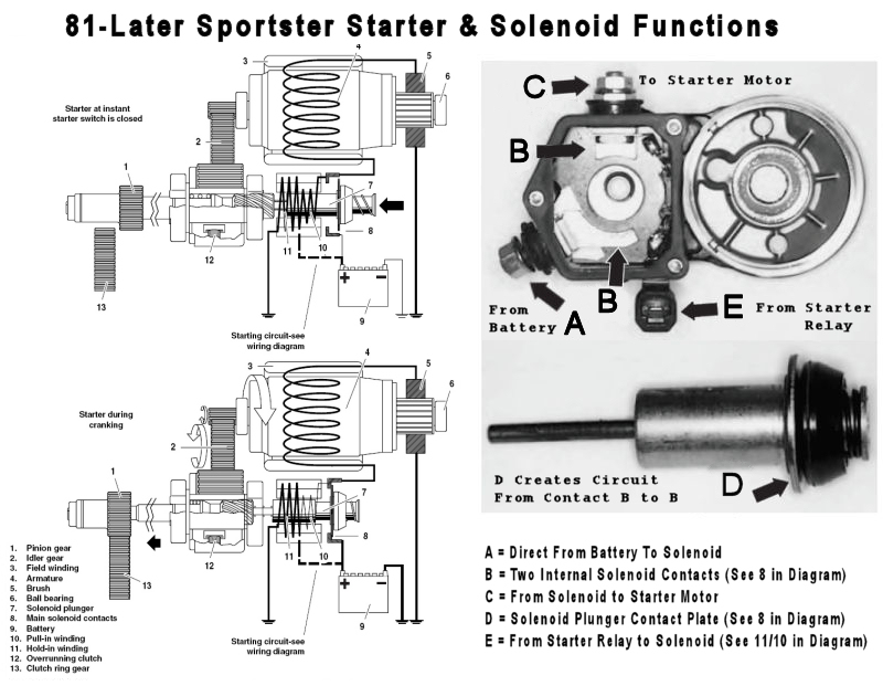
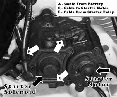
There are three external cable connections at the Starter Solenoid (see the diagram below):
(A) Cable From the Battery Positive Terminal - This direct cable supplys high current for the internal solenoid contacts (B).
(C) Cable to the Starter Motor - Short, high-amperage cable as part of the starter/solenoid assembly.
(E) Cable From the Starter Relay - A 12v positive signal.
The internal contacts (B), (D) & (B) create a high-current switch, which is operated by the plunger as it moves the pinion gear forward. When the plunger moves sufficiently forward, the plunger contact plate (D) is brought into contact with both (B) contacts, thus acting as a switch. This provides direct battery power from contact (A), thru contacts (B)(D)(B), and out contact (C) to the starter motor.
Here's a diagram of the Starter/Solenoid Assembly:

Technical Note - The pull-in windings are needed to initially move the plunger. Both the pull-in and hold-in windings are activated when the starter relay activates the solenoid. The power to the pull-in windings completes its path to ground thru the motor windings, while the hold-in windings have their own permanent ground path. Once the plunger moves forward into position, and the high-amperage contacts are closed, the pull-in windings are essentially disabled because the power on the output contact (B) makes both sides of the pull-in winding equal to 12v. This leaves only the magnetic field of the hold-in windings to keep the plunger in place.
In the left diagram above, the high-amperage internal solenoid contacts (B)(D)(B) are labeled '8'. The solenoid activation circuit (which includes the Starter Switch and the Starter Relay) is only identified with the dotted line from the battery to the windings at '10' & '11'.
When the solenoid plunger moves the pinion gear ('1') into mesh with the ring gear('13'), the starter motor is already starting to turn and helps the gears to mesh laterally. Once engaged, the starter motor will continue to rotate the ring gear (as long as the starter button is pressed) until the engine fires. At that point, the overrun clutch ('12') in the solenoid gear assembly allows the ring gear to run faster than the pinion gear shaft without harming the starter unit. When you release the starter button, the solenoid will retract the pinion gear from engagement with the ring gear and the starter unit will return to a resting state.
Note the following currents utilized in the various devices:
- 0.2amps pulled thru the Starter Switch (to the Starter Relay Coil)
- 20amps pulled thru the Starter Relay (to the Starter Solenoid Coil)
- 200amps pulled thru the Starter Solenoid Hi-Current Contacts
(to the Starter Motor when engaged with the Ring Gear)
Testing the starter circuit on the bike
Start with testing the Battery Voltages and Grounds as described **HERE**. You'll need a multimeter with voltage and resistance scales. Whenever you have power issues, its important to make sure the battery connections are 100% solid.
Select a 20v DC scale on your meter. Ground the meter to the battery or frame (if you have a good frame ground). Put your red meter probe on terminal 'A' and measure the voltage there - make sure it reads the same as the battery positive terminal.
Note: To make sure the engine does not start while working on it, remove the input connector or Pink wire from the ignition coil. Do not remove the spark plugs because you want the load of cylinder compression on the starter motor while you test it.
To test the starter relay, put your meter probe on the solenoid activation connector 'E' with its cable still attached. With the bike keyswitch and Run/Stop switch on, press the start button. You should read the voltage here at the same voltage level as the battery positive terminal (under the starter load).
If the starter relay proved good, then, put your probe on terminal 'C' and press the start button again. You should read a voltage here equal to the battery positive terminal (under starter load). This will prove the internal high-amperage contacts are sending power to the starter motor.
Those tests will give a good indication of where the problem may be located. Wherever the power is not full strength, or if it is totally missing, the test indicates the previous part of the system is not working.
Be sure to reconnect your coil input connections.
Testing the Starter Assembly while off the bike
Refer to your HD Service Manual for complete procedure related to starter removal.
- THE KEY SWITCH MUST BE OFF!
- You must place the transmission in neutral - MAKE SURE!
- Disconnect the NEGATIVE battery cable AT THE BATTERY
- Disconnect the POSITIVE battery cable AT THE BATTERY - Isolate this cable completely - Insulate this cable end with a non-conductive cover, like wrapping it in a clean shop rag.
Disconnect all wires from the Solenoid Connection 'A' - WARNING - THIS MUST BE DONE ONLY AFTER THE OTHER END OF THE POSITIVE BATTERY WIRE HAS BEEN REMOVED FROM THE POSITIVE BATTERY TERMINAL!!
Disconnect the Solenoid 'E' connection (which normally comes from the Starter Relay).
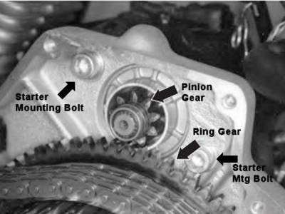
In order to remove the Starter, you must take off the Primary Cover. Then remove the two bolts that hold the Starter in place. You can see those two bolts in this picture, which also shows the Pinion Gear and the Ring Gear.3)
BE CAREFUL! - Because the starter will tend to rotate due to the torque, once the starter is off the bike! MOUNT THE STARTER SOLIDLY IN A VICE TO DO THE FOLLOWING TEST!!! Wrap the starter in a clean rag before vicing to protect the starter finish.
WARNING! Even without turning the engine (since the starter is on the bench), the starter motor will draw a large amount of current, up to 100 amps. This requires a heavy gauge cable for the power connections. Use a quality set of jumper cables (heavy gauge) to connect power & ground to the starter motor. Always be careful of your connections to prevent shorting the positive to negative connections. The battery is capable of producing more than 300 amps in a dead short, which will melt most cables & create a burn/fire hazard!
To test the starter & the solenoid together, the starter needs to be connected to solenoid terminal 'C' (which it should be as the unit is taken off the bike). Using a shop rag carefully arranged to prevent shorting to the starter/solenoid case, connect the positive cable from a battery to solenoid terminal 'A' shown in the above image. Connect the negative cable from the battery to the body of the starter/solenoid housing.
Now, using a 12-gauge wire, connect a jumper wire to the solenoid 'A' terminal, being careful not to short it to the case. Use the other end of the jumper wire to make a brief connection to the solenoid activation connector 'E' (where the starter relay would normally be connected) - When you apply 12v to that connector, it will cause the solenoid to activate the pull-in windings and move the plunger. The pinion gear on the end of the solenoid plunger should project out AND the starter motor should spin because the internal high-amp connection (in the solenoid) will be making a circuit from terminal 'A' to terminal 'C'.
Remove the ground connection from the starter/solenoid immediately after the test. Then remove the positive.
If the solenoid and starter do not function strongly, you may want to do the test below of the Solenoid Wiring Circuits.
Or, if the solenoid appears to strongly move the plunger, you may decide to disassemble the solenoid to check the high-current contacts which operate the starter motor. Check the quality of both internal contacts labeled 'B' (in the picture above) and check the plunger contact 'D'. If you find that the internal contacts are unevenly worn, badly pitted or mis-aligned, you may need to replace them. There are rebuild kits for the solenoid which includes the plunger and new contacts.
See this __XLForum Thread by YoungIronG__ & this __XLForum Thread by DogBunny__ for very helpful pictures and discussion.
Additional Reading Here:
http://xlforum.net/forums/showthread.php?t=1870819
http://xlforum.net/forums/showthread.php?t=1872862
http://xlforum.net/forums/showthread.php?t=1941512
Testing The Solenoid Wiring/Circuits
 This test is best done with the starter/solenoid removed from the bike. Because of the potential for shorts, we do not recommend testing the wiring circuits while the starter/solenoid is in place on the bike.
Read and follow all the precautions listed above for 'Testing the Starter Assembly while off the bike' to safely remove the starter from the bike. Once the starter/solenoid is safely off the bike and on the bench, you can proceed to test the solenoid windings.
IMPORTANT! Disconnect the Solenoid 'C' connection to the Starter Motor. We do not want to spin the motor. Place the wire out of the way, where it cannot accidentally make contact with Connection 'C'. This completely removes the starter motor from the equation.
You will need a typical, fully charged, 12v battery to run these tests. Use jumper wires capable of handling the current (up to 20 amps) the solenoid draws. Use quality 12-gauge wire.
Make two insulated jumper wires (12 gauge) long enough to reach from the solenoid to the battery. One is solidly connected to the Solenoid 'C' connection & the other is solidly connected to the Solenoid 'E' connection.
The testing requires both wires to be moved between the two battery terminals, so holding them carefully by the insulation, one in each hand, should provide a safe and quick way of moving the connections.
Use another jumper wire from the NEGATIVE battery terminal to the case of the solenoid body and secure it well.
Double Check for Safety - At this point, you should have no connection at the Battery Positive Post and no connection at Solenoid Connection 'A' - The jumper wires are connected to Solenoid connections 'C' and 'E' with a ground wire from the solenoid body connected to the NEGATIVE battery post.
Now the test - This sequence is done quickly, moving swiftly from one connection to the other.
… Do not linger and do not hold any connection more than 3-seconds:
Be sure to follow your HD Service Manual when reinstalling the starter/solenoid (essentially the reverse of its removal).
Starter Solenoid Rebuild Kits
Starter Solenoid Rebuild Kits (OEM - for stock starter solenoids):4)
1981 through 1990 XLH ………. use Kit 31605-90
1991 and later XLH 1200 …….. use Kit 31603-91
1991 through 1994 XLH 883 …… use Kit 31605-90
1995 and later XLH 883 ……… use Kit 31603-91
The rebuild kits (in general) will include these new replacement parts:
- Solenoid Cover Gasket
- Solenoid Plunger (w/o spring)
- Solenoid Input Contact Assembly (contact, bolt, nuts, washers, insulators)
- Solenoid Output Contact Assembly (contact, bolt, nuts, washers, insulators)
Naturally, aftermarket kits are available - check those for compatibility.
Caution
1989 through 1990 Big Twin ….. use Kit 31608-90
1991 and later Big Twin …….. use Kit 31604-91
31619-06A (Black), 31621-06A (Chrome) 1.4KW Starter5)
This starter is defined to fit 2006 and later Dyna, and 2007 and later Softail and Touring model motorcycles. From examining the solenoid rebuild kit (31604-06) for this model, it appears the solenoid plunger rod is longer than that used with the Sportster 1.2KW stock model starter. So this kit may not work with the XL models.


