This is an old revision of the document!

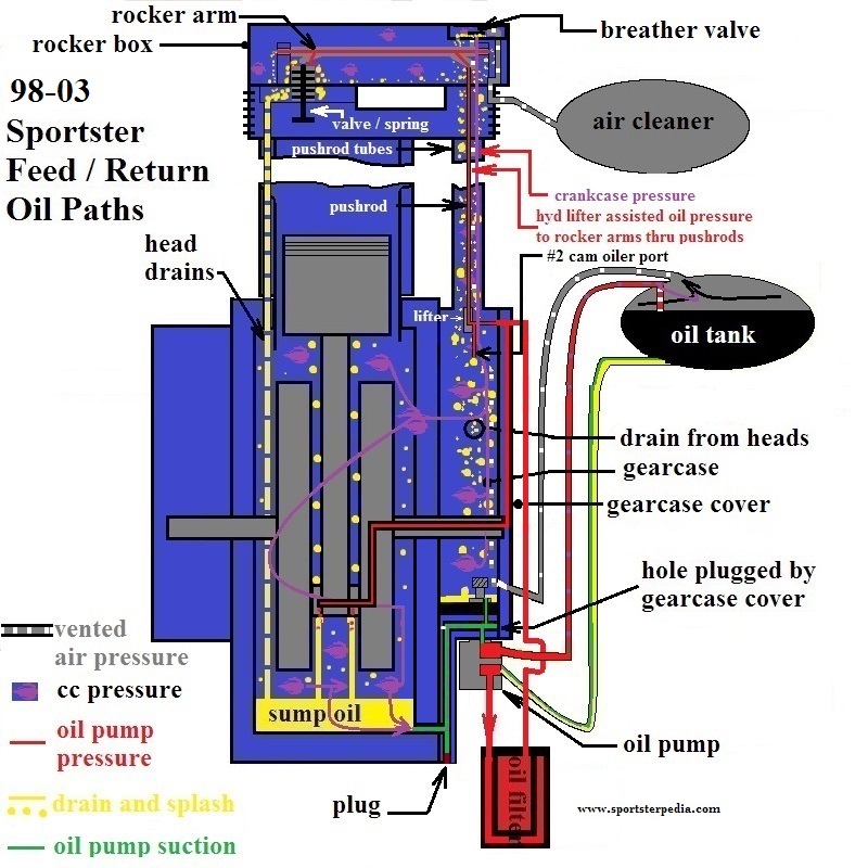
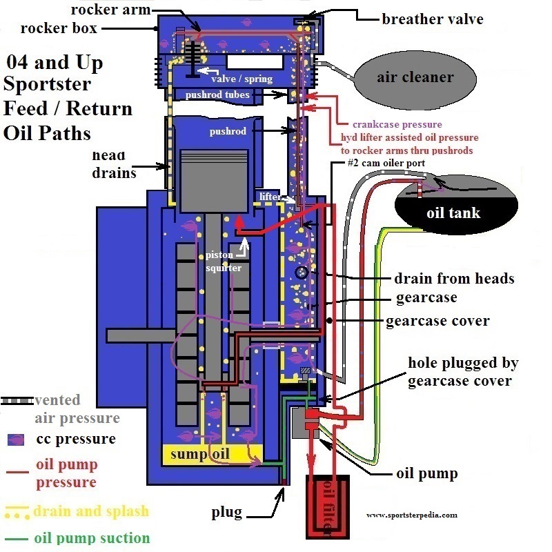
EVO: Oiling & Lubrication
Engine Oil Routes
Oil Paths:
Click on a drawing to enlarge:


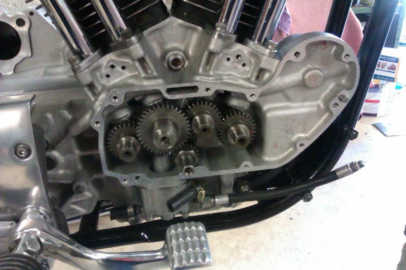
Oil Passages From The Filter Pad
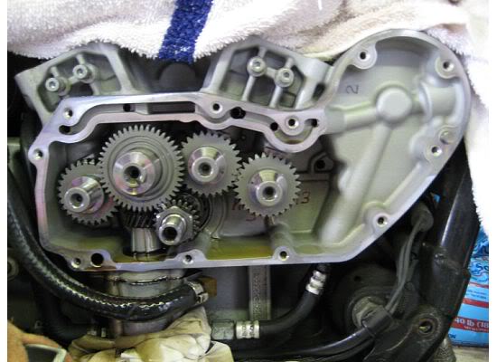
Below are different cam chest pics showing the oil passages from the filter pad.
| 86 Cam Chest 6) |
 |


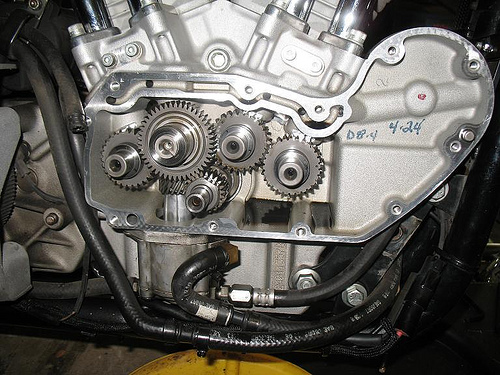
| 2013 Cam Chest 17) |
 |
| XR1200 Cam Chest 18) | |
 |  |
Right Crankcase Feed Galley
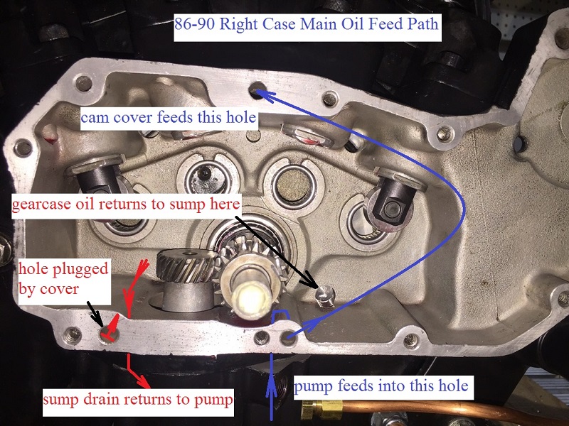
86-90 engines
The lifter oil feed galley is a hole located along the top of the case between both intake tappets.
- The feed galley is responsible for carrying oil to the lifters.
- It gets it's oil from the cam cover.
- A hole is internally routed from the top to the bottom of the cover with a hole exiting in a corresponding hole in the case.
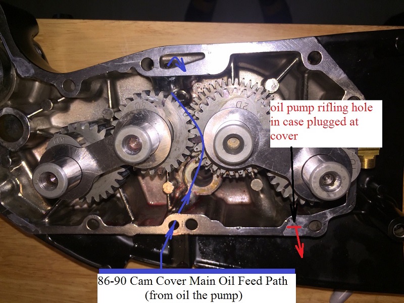
- The cam cover gets it's oil from the oil pump via intersecting holes between the bottom of the case and the cover.
- Feed oil is routed inside the cover but not to the gearcase.
- The hole in the middle of the case at the top intersects into the internal oil feed galley.
- Cross drilled passages intersect the main feed galley and carry oil to each intake lifter.
Exhaust lifters are fed oil (bore to bore) from a drilled passage into each one's respective intake lifter bore. - This is the end point of static oil pump pressure to the top end.
- The lifters supply oil pressure to the rocker boxes.
| 86-90 main oil feed path 19) | |
 |  |
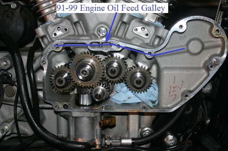
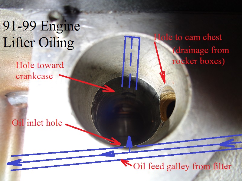
91 and up engines
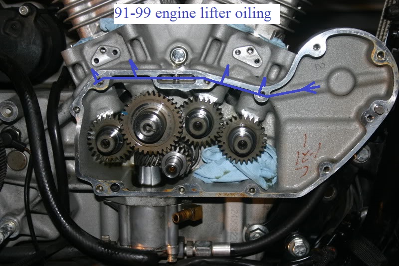
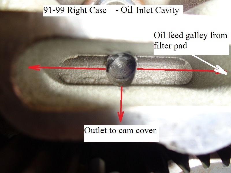
The main oil feed galley is a horizontal passage located along the top of the case beside the tappet blocks and lifters.
It runs from the filter pad to the last lifter bore (lifter for #1 cam).
This oil galley feeds the lifters, cam cover / pinion shaft / hole in pinion gear to the rod bearings and also the gears on cam #2.
- The feed galley is responsible for carrying oil into the engine.
- It gets it's oil from the filter / check ball.
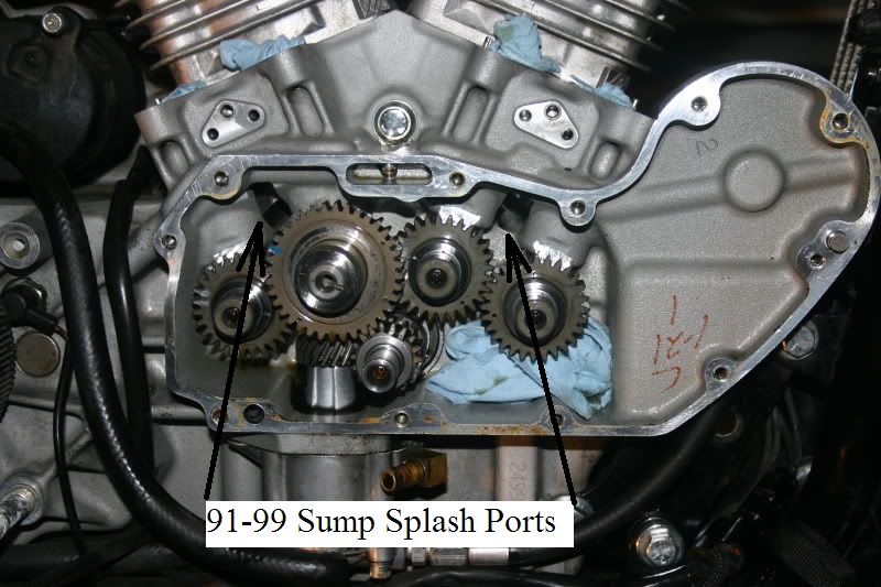
- 91-99 engine feed galley is an internally drilled hole in the case.
- It runs behind and into on both sides of the small cavity (small slot) milled into the outside edge of the case.
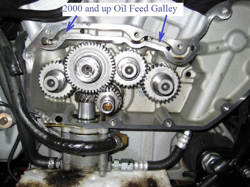
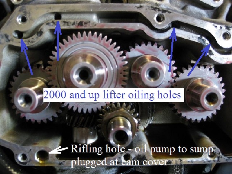
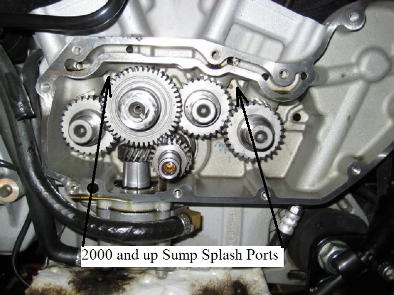
- 2000 and up engine feed galley is an external slot milled into the outside edge of the case.
- The oil passage runs on the outside (right) of the lifter bores as in 91-99 cases with a hole drilled through it into each lifter bore.
- Cross drilled passages intersect the main feed galley and carry oil to each lifter from the feed galley.
- This is the end point of static oil pump pressure to the top end.
- The lifters supply oil pressure to the rocker boxes.
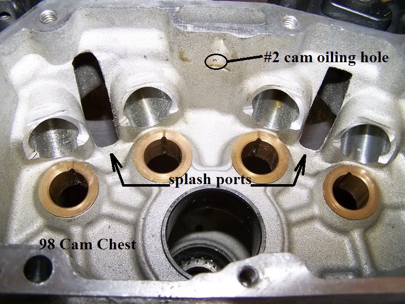
- A small amount of oil sprays down onto the rear intake (#2) cam gear through a tiny hole in the middle of the feed galley.
- The cam cover gets it's oil from an intersecting passage in the feed galley at the top of the cover.
(the gearcase gets no oil from this passage in the cover, outside of spill from the pinion shaft bushing)
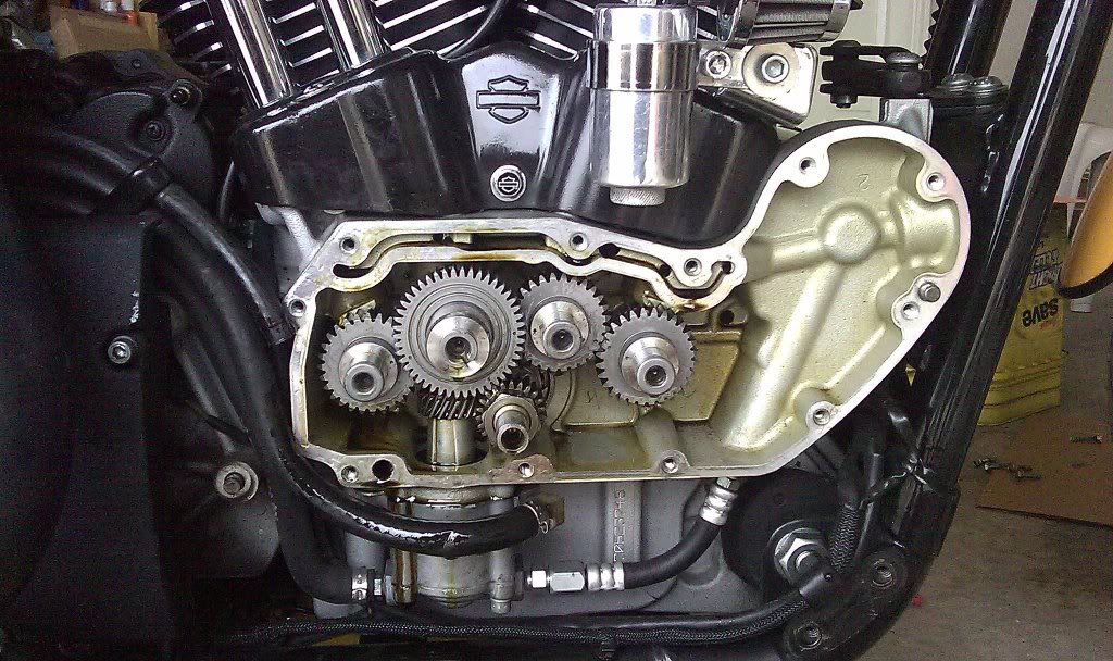
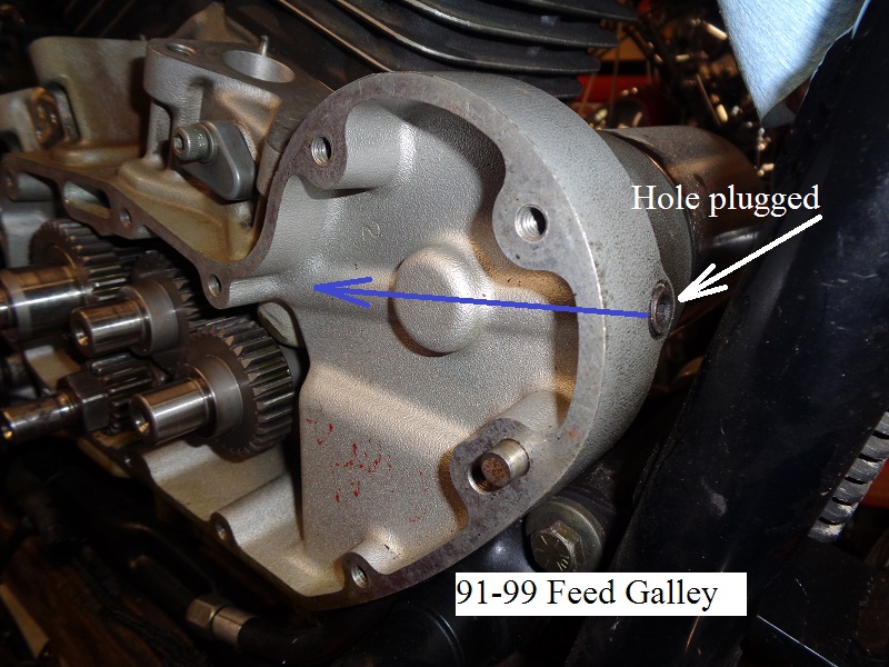
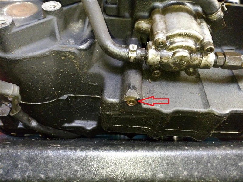
In examining the area directly behind the filter inside the gearcase;
You can see the oil path (channels from the filter to the engine).
There is a plug on the outside case in the area of the filter.
The plugged hole is from where the MoCo drilled the oil passage to connect the outlet of the oil filter to the lifters. 20)
After they drill it, they stick a plug in it.
There are other plugged holes like that on your motor where the drilling operation left a hole that had to be plugged.
Top End Oiling
Lifter oiling
1986-up Sportsters were fitted with hydraulic roller lifters (roller tappets) from the factory.
- Each lifter has needle bearings inside a wheel that is held in place by a solid axle.
The wheels / bearings for 1991-up lifters cannot be replaced as the axle is not removeable. - Each lifter is compiled of 2 main bodies, an outer (lifter body) and an inner (cartridge body, AKA plunger).
- Both the lifter body and plunger have a machined recessed area (oil band) around the outer circumference to circulate pressurized oil around it.
The lifter body also has an inner oil band to transfer oil to the internal body cartridge (plunger).
The oil bands insure oil is transferred to the inside of the plunger reservoir (no matter of it's inlet positioning). - There are two separate cavities; 1 in the bottom of the lifter body (pressure chamber) and 1 inside the plunger (oil reservoir).
The pressure chamber is what actually does the lifting on the engine valve.
The oil reservoir feeds both the pressure cavity and the rocker arms. - Sitting directly under the plunger is a check disc assembly.
There is a very thin solid disc smacked against the hole in the bottom of the plunger.
The disc is held against the plunger by a spring below it and both captured by a metal housing pressed onto the bottom of the plunger.
The disc opens allowing oil into the chamber and oil to leave the chamber at different times. - Sitting on top of the plunger reservoir a metering disc under the piston cup. Both the metering disc and pushrod cup sit on a shelf machined in the top of the plunger.
The assembly is held in place by a retainer clip fitted into the machined cup in the top of the lifter body.
The metering disc is another restriction in the oil path to regulate the amount of oil delivered into the pushrod.
More importantly, it retains a certain amount of pressure below it in the plunger reservoir to quickly fill the pressure chamber.
The pushrod cup is concaved to match the shape of the pushrod end that stacks on top of it.
Engine valve pressure creates a seal between these two parts.
The drawing below is of a 1991-1999 Sportster OEM lifter and shows the parts mentioned above. However, 2000-up Sportster lifters have the same parts.

There are, however, hydraulic lifter designs that completely cut off the oil feed when you come off the base circle.
For example:
 27)
27)
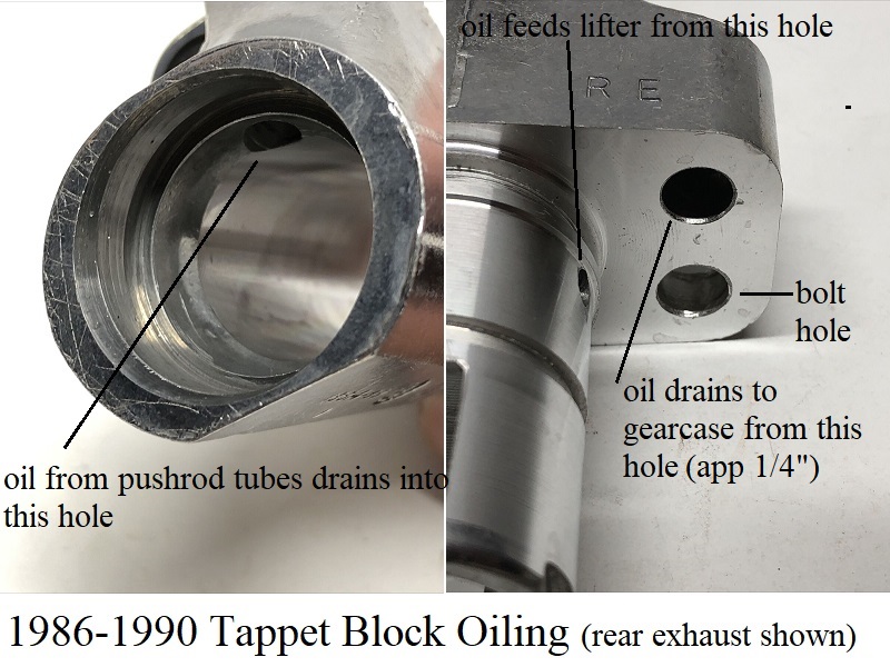
86-90 engines:
The oil feed to the lifters comes from the oil pump, through a passage in the cam cover to the feed galley in the top of the right case.
The intake lifters are fed oil from the feed galley hole.
Each exhaust lifter is fed from it's corresponding intake lifter bore.
| 86-90 lifter oiling path 28) |
 |
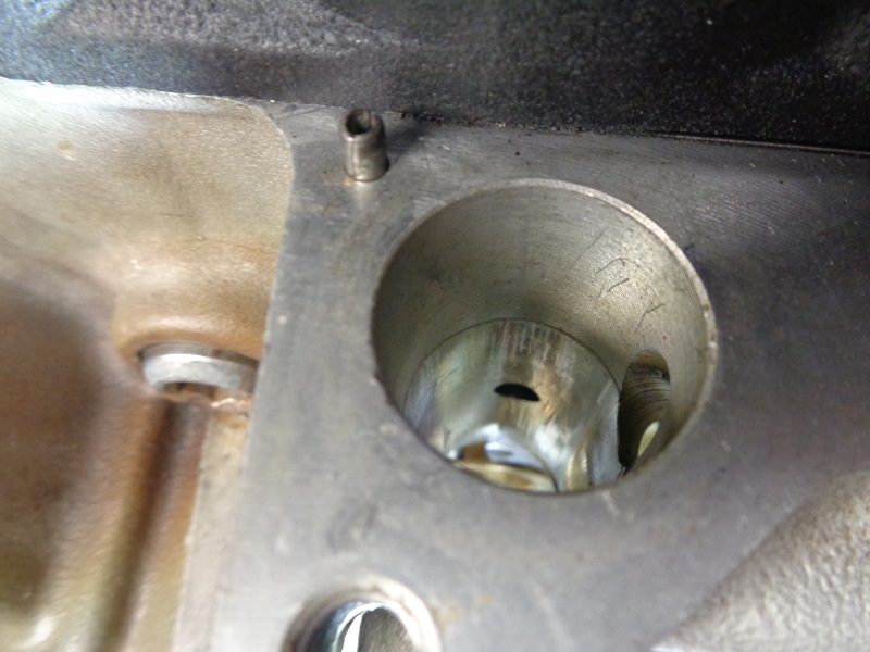
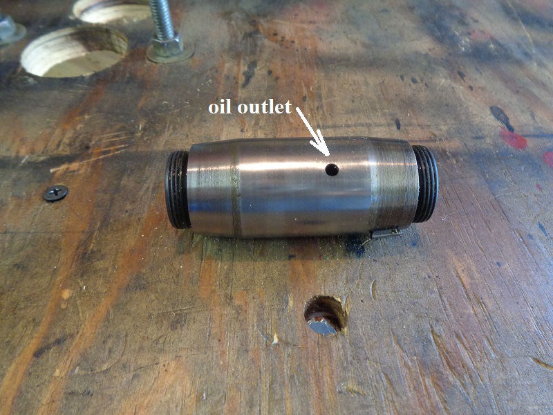
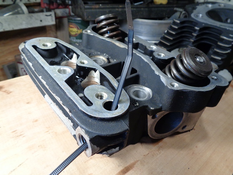
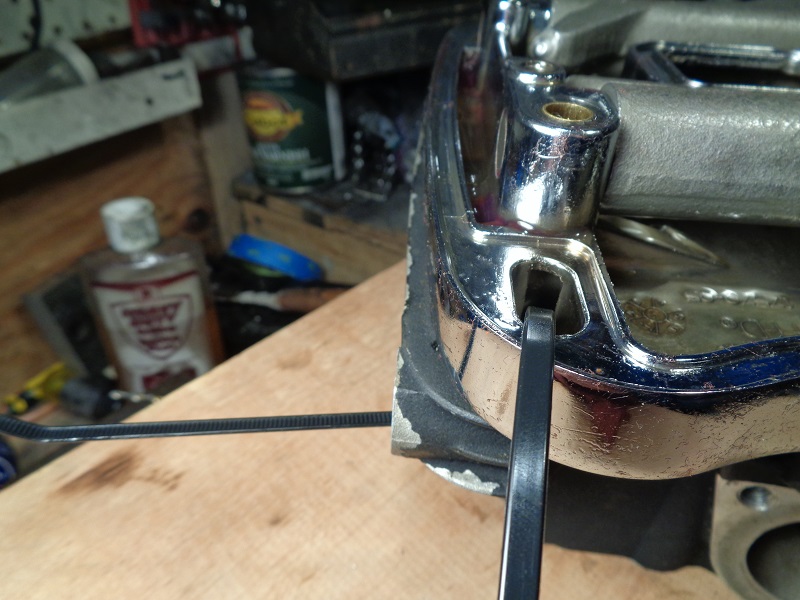
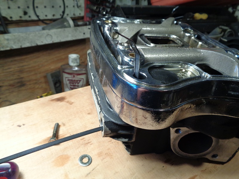
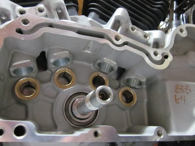
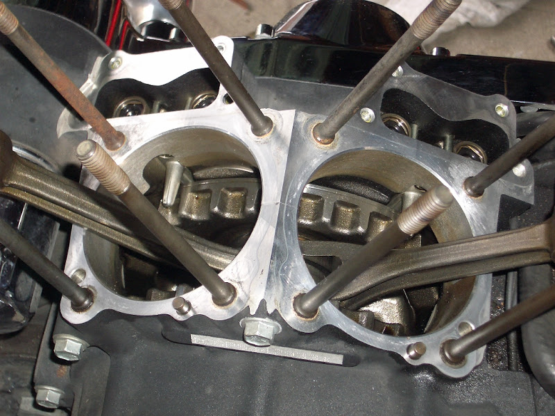
91-99 engines:
The oiling hole for the lifters in 91-99 engines is drilled from the inside of the right case out through the lifter bore and into the case oil galley.
All four lifter bores are capped on the inside of the right case.
This left a blind hole between each lifter toward the inside of the case.

| 91-99 lifter bore 31) | |
 |  |
| A look inside the oiling holes in the lifter bore on a 91-99 case. Notice the capped hole toward the case in the third pic. 32) | ||
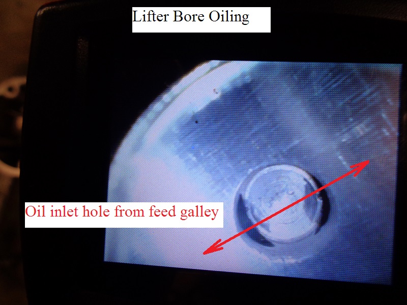 | 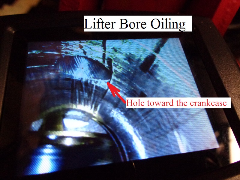 |  |
2000 and Up engines:
However, the oil galley was now cut into the right case instead of a rifle drilled hole.
This made it easy to drill oiling holes to the lifters from the outside of the case into the lifter bore.
So there were no lifter oiling holes to cap on the inside of 2000 and up cases.
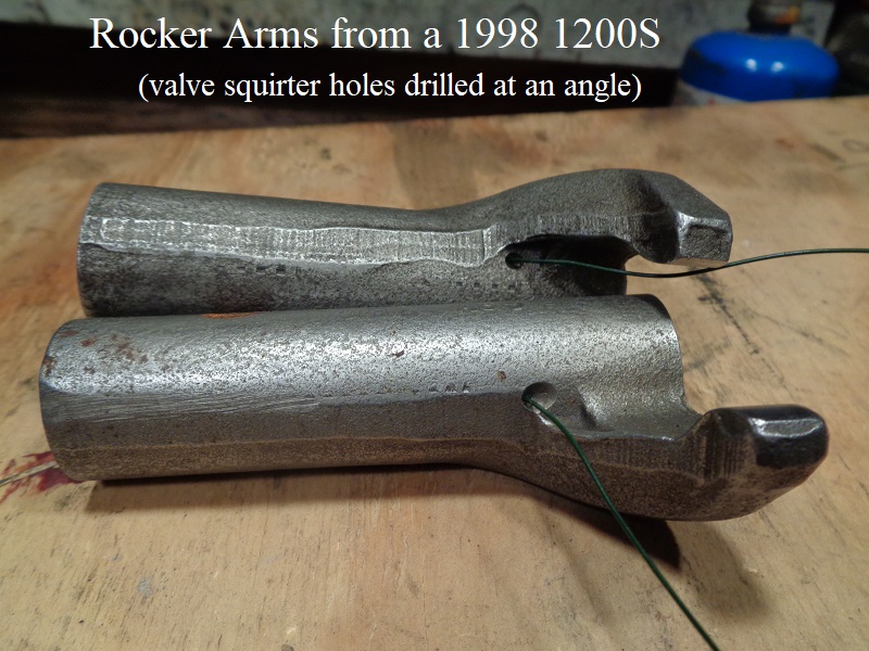
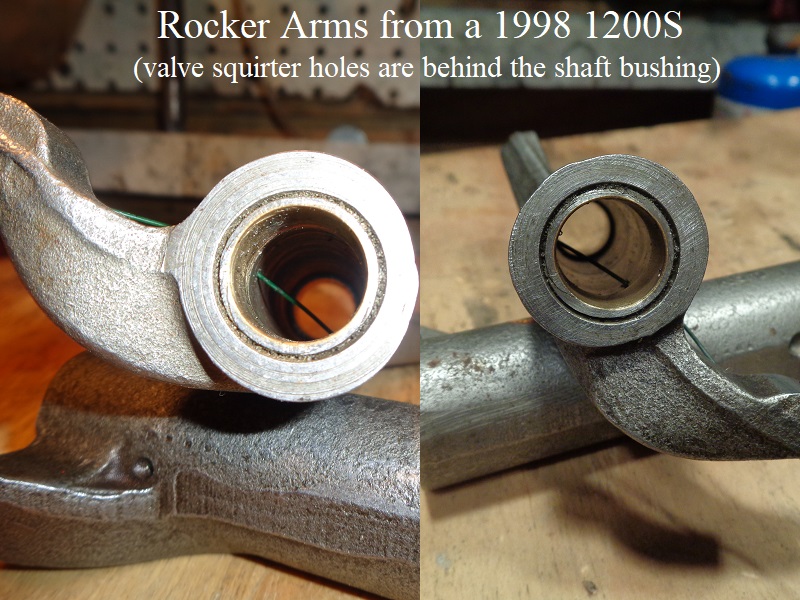
Rocker arm / Valve oiling
All
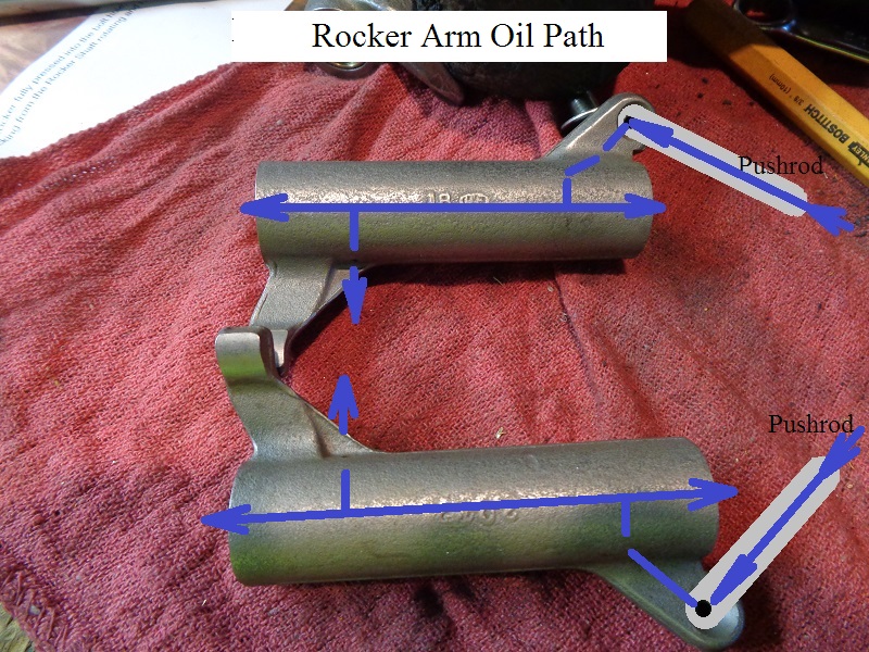
- Oil flows up the holes in the pushrods from the lifters and enters the rocker arms through a hole in the pushrod end of the arm.
- Oil is supplied to each valve stem and springs from the drilled holes in the underside of each rocker arm above them.
- The holes are only on the valve side of each rocker arm.
- Oil is also forced through the clearance between the rocker arm shafts and bushings for lubrication there.
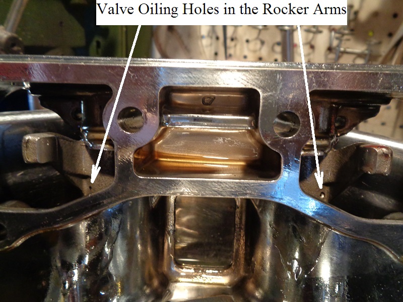
| Valve Squirter Hole Locations 37) | |
 |  |
Rocker Box Oiling
91-99 engines
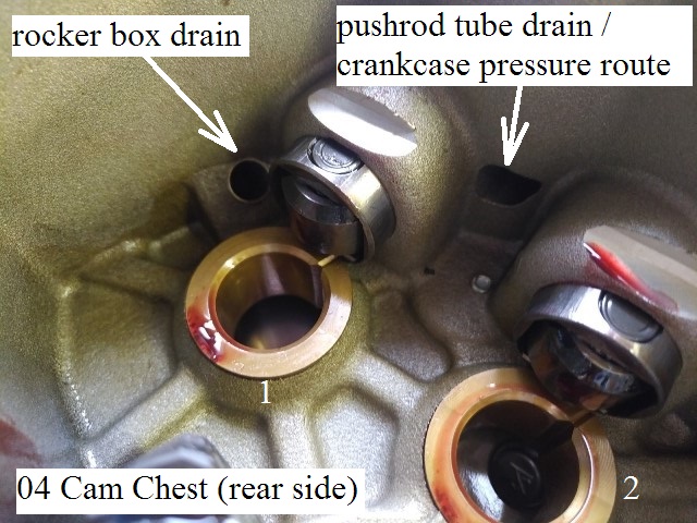
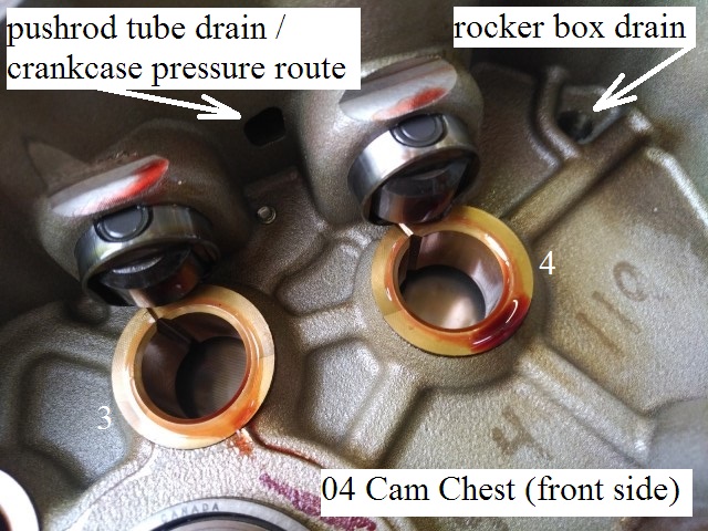
- Crankcase pressure (air and oil mist) is routed up the pushrod tubes (bypassing the falling oil from the rocker boxes) into the rocker box.
- Collected air pressure and oil mist in each rocker box is routed up into a sealed cavity in the lower portion of the box.
- This mixture passes up from underneath a rubber one-way valve (umbrella valve) sitting over the cavity inlet.
- The oil is designed to separate from the air by;
- Hitting the underside of the umbrella valve and falling back into the sealed cavity in the middle rocker box.
- From there it should drain back into the lower rocker box through a tiny hole behind the umbrella valve.
- This tiny hole is in a recessed area behind the umbrella valve.
- There is a certain amount of backpressure in the sealed cavity away from the air exit hole.
- This backpressure should help push the oil into the tiny hole and back into the lower rocker box area to be carried back down to the lower end.
- The upstroke of the pistons causes a vacuum to form in the system.
This vacuum is also pulled through the oil passage from the heads / rocker box.
(in theory, it should help pull oil through the drains in the heads to the bottom end.
- Air pressure is designed to continue up past the umbrella valve and exit a hole in each head on the intake valve side.
- Pressure escapes the head through the hollow bolts (one in each head) that hold the air cleaner mount.
2000 and Up engines
Bottom End Oiling
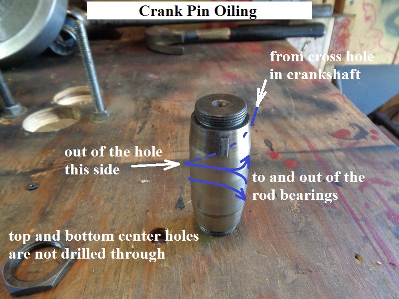
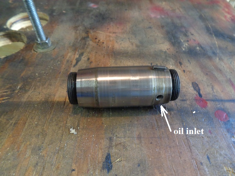
Pinion shaft and Crank Pin
All
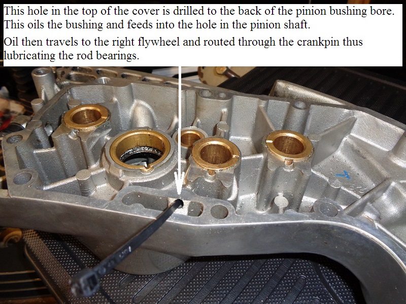
- Pressurized oil in the pinion bushing is sent through a hole in the (hollow) pinion shaft toward the flywheel.
- Oil travels to and through the right flywheel via an internal passage from the pinion bore and the crank pin bore in the flywheel.
Oil enters the crank pin inside the crank pin bore on the flywheel. - Oil is routed out of the crank pin through a hole under the rod bearings in the middle of the pin and circulates to the rod bearings.
- This is the end point of static oil pump pressure to the bottom end.
- Oil leaving the rod bearings flows into the crankcase to be scavenged by the oil pump (or splashed into the gearcase).
- Crankcase pressure moves the oil from this point.
| L81-03 'one hole' crank pin. 38) | ||
 |  |  |
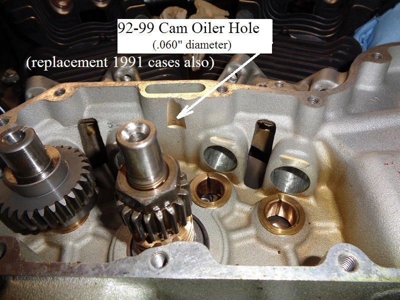
Cam Oiling
- Oil flows off the pushrod side of the rocker boxes through the pushrod covers, into vertical holes in the lifter bores and into the gearcase.
- Oil falls on the cam lobes on the way down this hole.
- Some of this oil is transferred between the gear teeth.
- The rear intake (#2) cam gets a little oil spray from the right case oil feed galley through the small orifice underneath the open cavity in the case.
- That oil is transferred between the teeth of the cams.
- Oil flung off the cams lands in the gearcase to be collected into the scavenge (return) side of the oil pump.
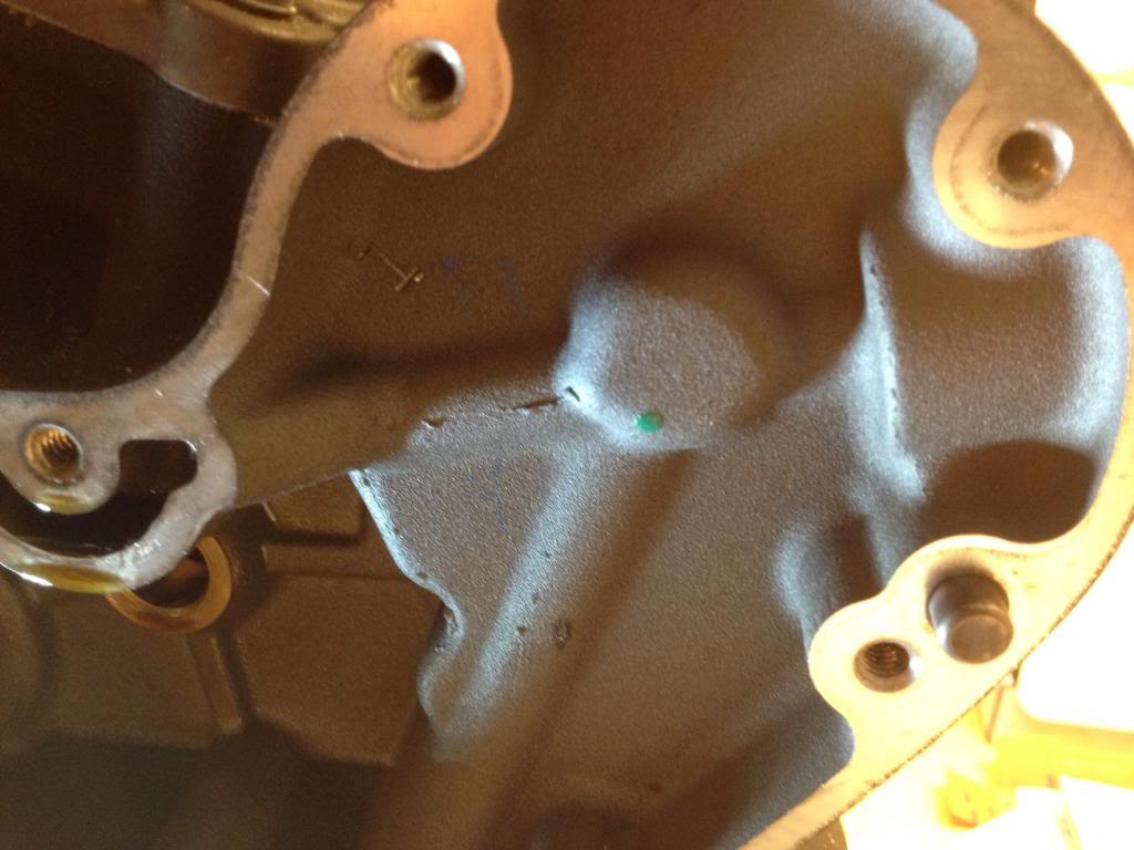
Below are pics of the restricted orifice underneath the oil feed galley in the case that shoots a small stream onto #2 cam.
#2 cam rotates counterclockwise and the oil is sprayed on the right side of the cam gear for extra cooling.

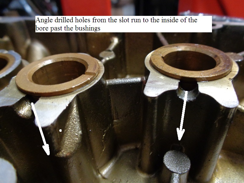
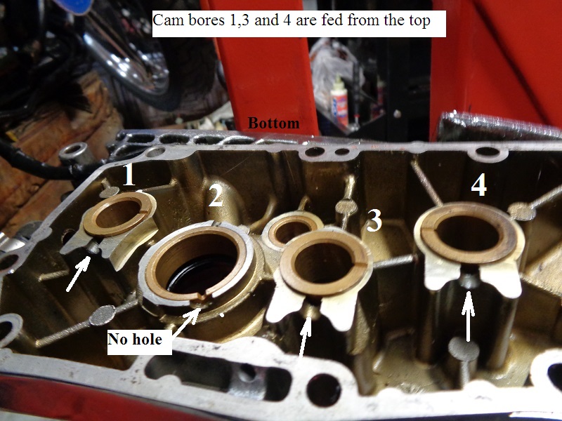
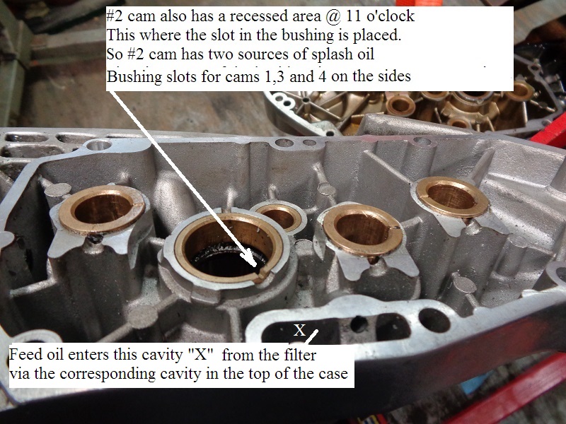
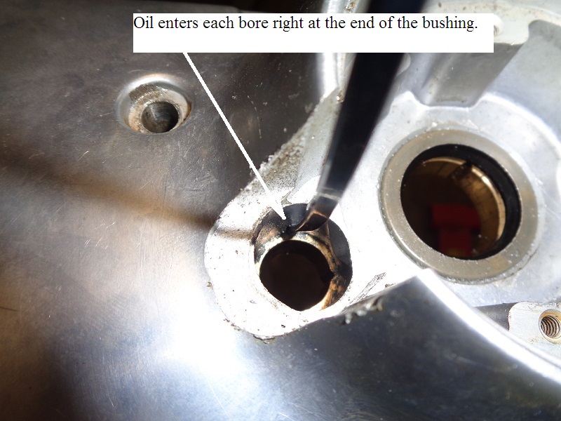
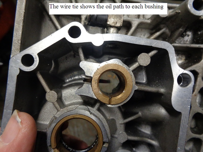
Cam Cover Bushings
All cam bushings are fed from splash oil into channeled holes drilled behind the bushing faces.
#1, #3 and #4 cam bores have channels drilled from the top down into the back side of the bores.
The channel for #2 cam bore starts at the bottom and is drilled into the back side of the bore.
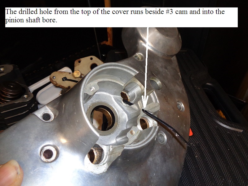
The pinion bushing (as well as the hole in the pinion shaft) is fed from a cross drilled hole in the top of the cover.
 |  |  |
 |  |  |
 |  |  |
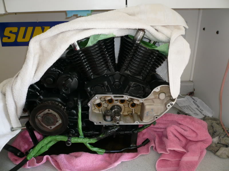
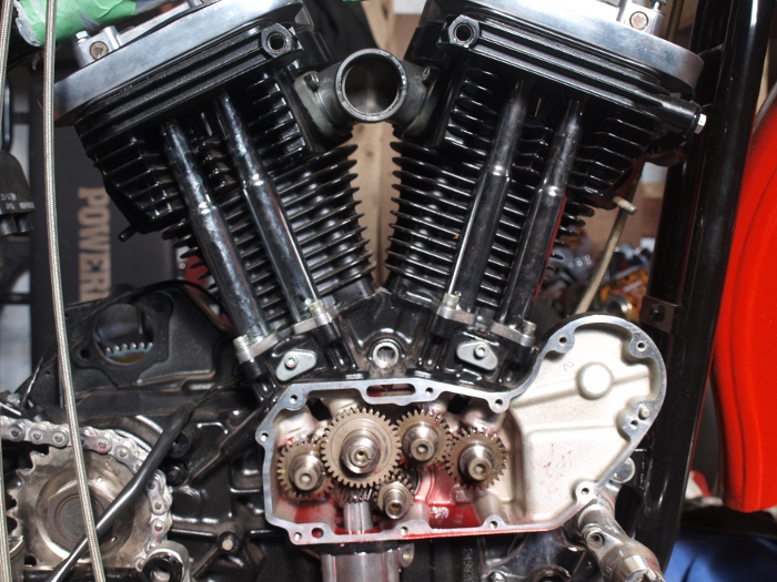
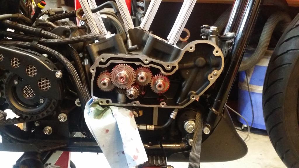
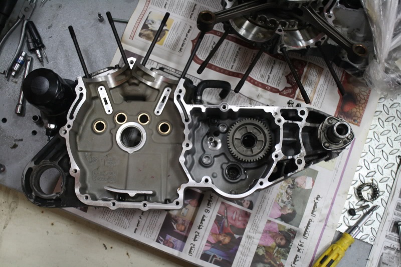
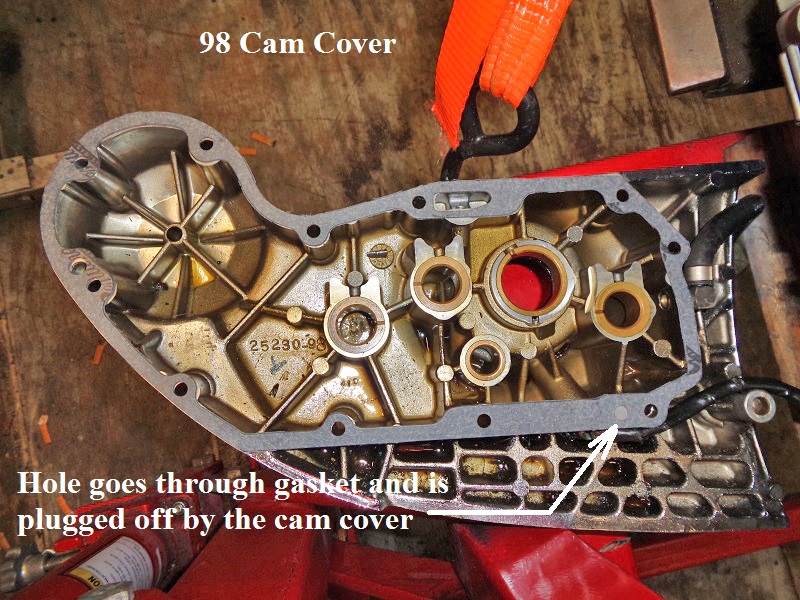
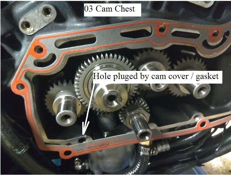
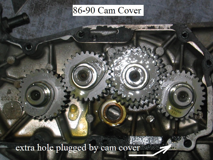
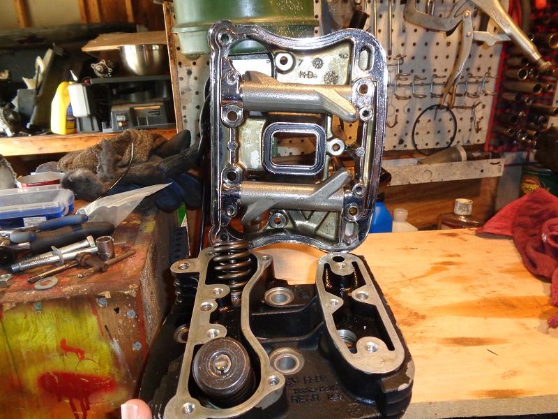
Cam Cover \ Gasket
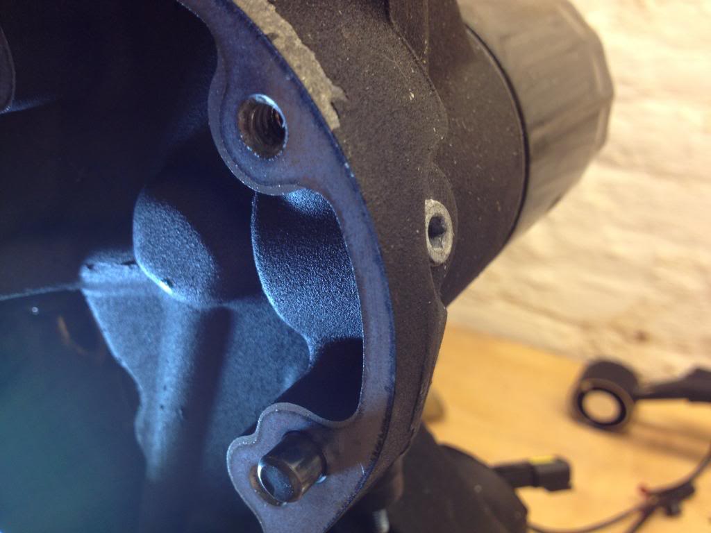
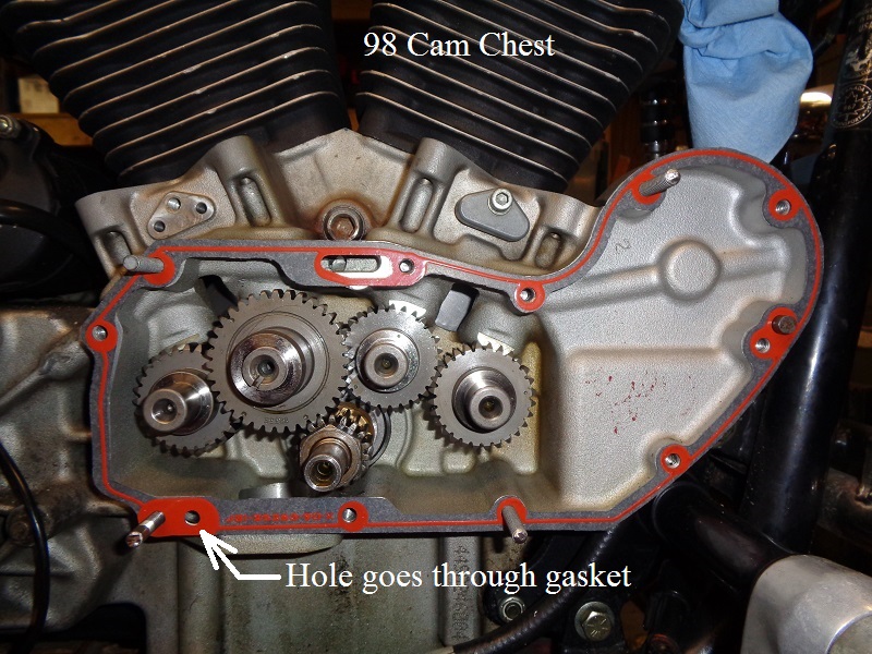
91 and up Sportster engines have an internal rifling hole drilled into the lower left side of the case running past the left side of the oil pump.
That extra hole (in the picture below) is benign and doesn't need a hole in the gasket to match.
That hole is purely an artifact of how they connected two passages for routing crankcase oil up to the oil pump's scavenge section.
They drill that hole to connect the two passages, and then it gets blocked off naturally by the cam box cover and gasket. 41)
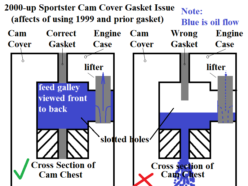
Also, in 2000, the factory changed the oil routing to the lifters to make manufacturing the cases easier.
The newer cam cover on the left in the pic below and has two extra grooves along the top.
These grooves let oil get to the lifters.
If you have an older style gasket, it will not have cutouts for the grooves and you won't get oil to the lifters.
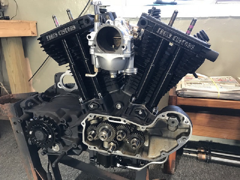
| Rubbermount Evo vs Rigid Evo Cam Cover Internals 42) |
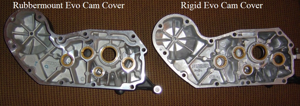 |
| Both have been chopped on the outside but the gearcase perimeter is intact on them for reference. |

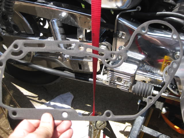
DON'T INSTALL a 91-99 CAM COVER GASKET ON A 2000-UP MOTOR!!!!!!!
The 91-99 cam cover gasket has no business being on a 2000+ motor at all. It will cause you to lose all oil pressure. 47)
The 2000+ gasket supersedes the 91-99 gasket. In other words, it can be used all the way back to 1991.
Most companies completely dropped the 91-99 specific gasket and only offer the one that can be used from 1991-present.
Either James Gasket hasn't done that, or they may have some old stock.
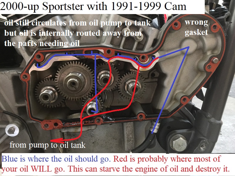
The 91-99 lifter feed galley is an internal rifling hole in the case. It's drilled thru the case and only open to the cam cover via the center port to the pinion bushing.
The 2000-up lifter feed galley is external and it takes both the cover and the case mounted together to make up the feed galley.
So 00-up feed galley is split in half between the case and cover. The slots in the 2000-up cam cover gasket mate to both the case and the cover.
If you have the correct gasket on there, oil would be forced (between the cover and case) to all the lifter feed holes and piston squirters.
With the wrong gasket (91-99), oil pressure leaving the filter gets into that (now open) galley.
Then the oil will blow into into the cam chest, therefore bypassing the lifters, piston squirters and rod bearings.
The oil will simply cycle from the oil pump to cam chest to oil pump and back to the oil tank.
The oil light will stay off so you'll get no notice before moving the parts start oil starving and making noises and worse if the noises aren't heeded to quickly.
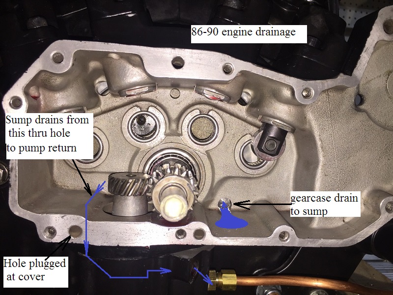
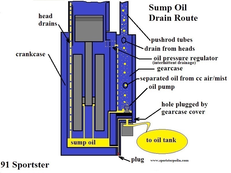
Case Oiling and Drainage
86-90 Engines
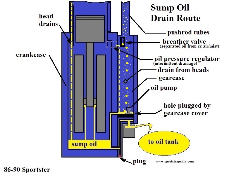
Gravity Drains
- Gravity oil (drained from rocker boxes and head/cylinder drainage) falls on moving parts and into the crankcase.
- Oil collected in the rocker box is returned to the crankcase through a passage in the cylinder and the head.
- Oil collected in the push rod areas of the heads / rockers flows down the pushrod covers.
- Then it flows down into the gearcase / cam chest through drain holes through in the tappet blocks.
- Collected oil in the gearcase is routed to the crankshaft sump area via a low hole in the wall between them on the right side of the pinion shaft.
- Excess oil mist drawn into the gearcase breather is separated from crankcase air pressure at the gearcase breather valve.
- The separated oil (and condensed oil in the exit hose) flows into a drain hole below the breather valve and back into the gearcase.
Tappet blocks are directional (rear exhaust shown below).
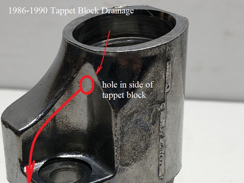 51)
51)  52)
52)
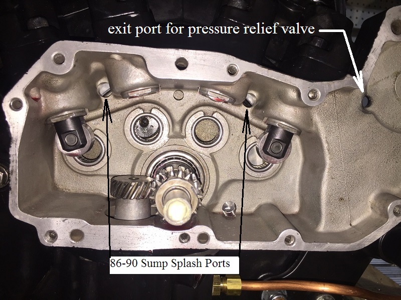
Splash
- Occasional excess pressured oil (from the oil filter pad) is dumped into the gearcase by the oil pressure relief valve.
- High pressure oil, when cold (on startup), opens the pressure regulator.
- The excess oil is dumped into the gearcase and routed to the sump area via the low hole in the wall between the gearcase and the crankcase.
- Splash oil in the sump area of the crankcase serves to lubricate the moving parts as well.
- Splash oil (from the up and down movement of the connecting rods, crankshaft and pressure generated under the pistons on downstroke) serves to lubricate;
- Cylinder walls
- Pistons, piston pins
- Cam gears and bushings
- Main bearings
| 86-90 engine sump splash holes 53) |
 |
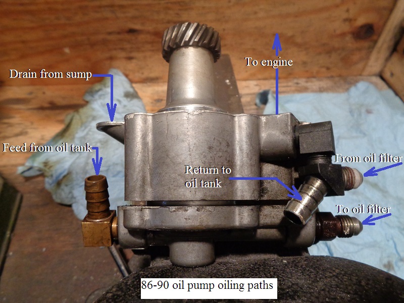
Oil Pump Scavenge
91-Up Engines
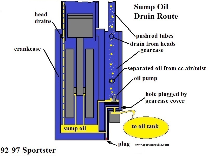

Gravity
- Gravity oil (drained from rocker boxes and head/cylinder drainage) falls on moving parts and into the crankcase.
- (91 only) - Occasional excess pressured oil (from the oil filter pad) is dumped into the gearcase by the oil pressure relief valve.
- 91 engines kept the oil pressure relief valve that opens at 30-35 psi and dumps oil into the gearcase.
- The pressure relief was removed from future models.
- 91-03
- Oil collected in the rocker box is returned to the crankcase through a passage in each head and cylinder.
- Oil collected in the push rod areas of the heads / rockers flows down the pushrod covers.
- Then it flows down into the gearcase / cam chest through vertical drain holes in the tappet blocks.
- Excess oil mist splashed into the rocker boxes is separated from crankcase air pressure at the breather baffles (plain umbrella valves).
- The separated oil flows into drain holes in the rocker boxes and back into the crankcase.
| Rocker box drainage 61) |
 |
| 91-03 breather holes in the rocker box sections and head 62) | ||
 |  |  |
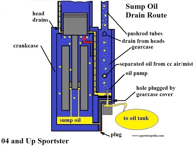
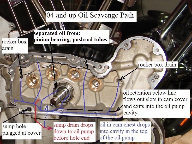
- 04-Up
- Oil collected in the rocker box is returned to the gearcase through a passage in the head and the right case.
- Oil collected in the push rod areas of the heads / rockers flows down the pushrod covers.
- Then it flows down into the gearcase / cam chest through vertical drain holes in the tappet blocks.
- Excess oil mist splashed into the rocker boxes is separated from crankcase air pressure at the breather baffles (fancy umbrella valves).
- The separated oil flows into drain holes in the rocker boxes and back into the gearcase.
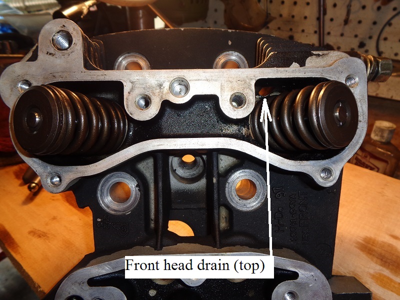
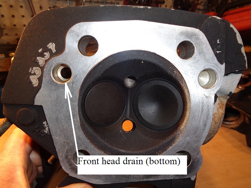
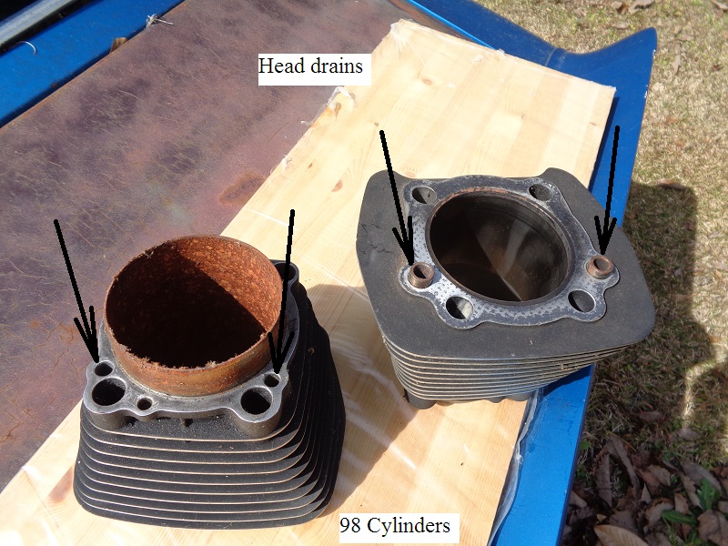
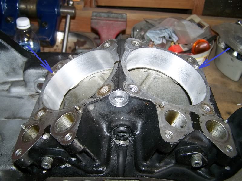
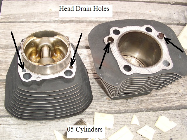
| Head drains in the cylinders 67) 1 hole is plugged on each cylinder during installation. | Head drains at the cylinder base on the case 68) |
 | 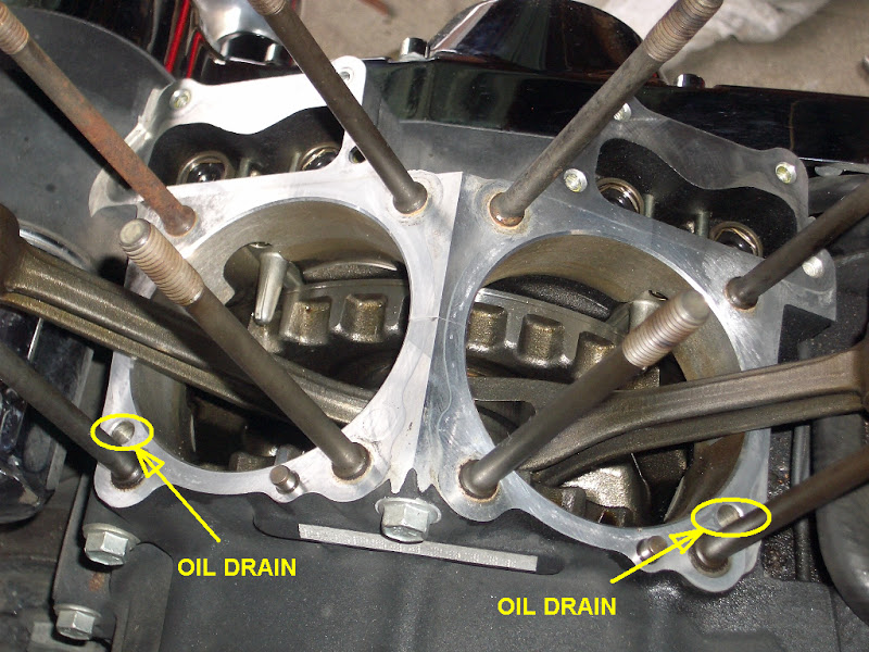 |
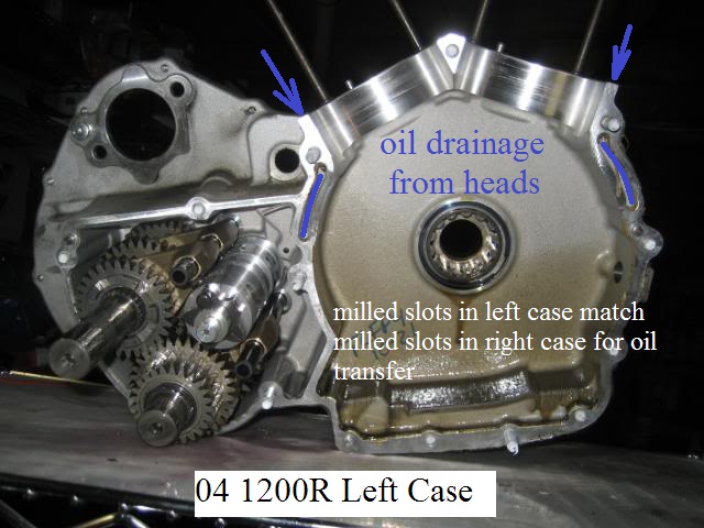
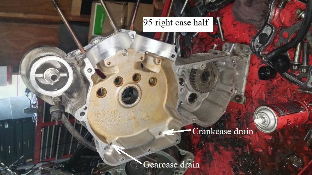
| Milled slots in the left case match milled slots in the right case for rocker box drain from valve side. 69) | Lower part of slots in the right case exit thru drilled holes into the gearcase. 70) | |
 | 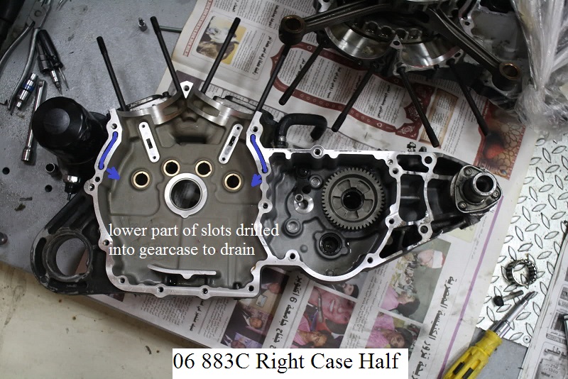 | 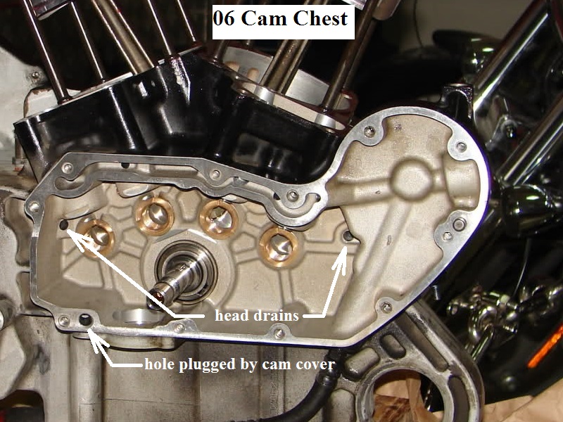 |
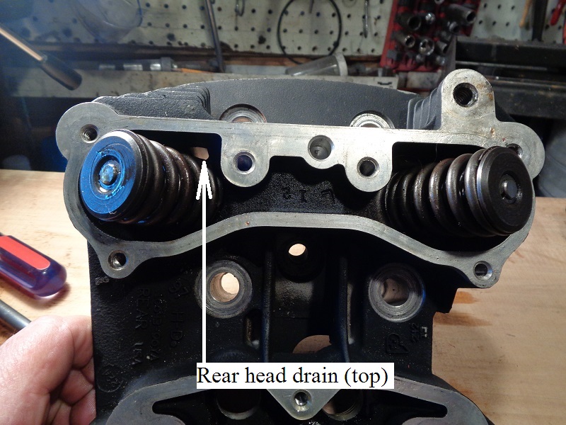
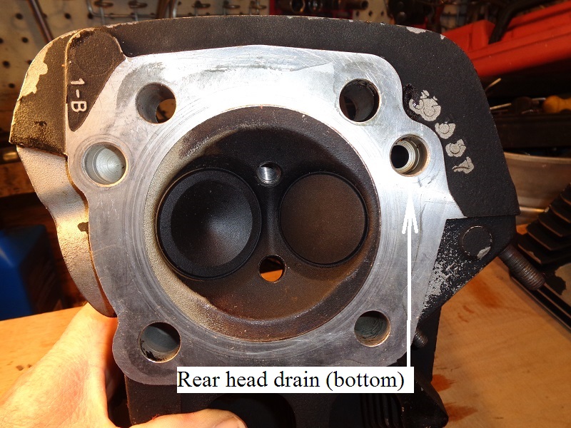
| Rocker box drains into the cam chest. 71) | |
 |  |
Splash
- Splash oil
(from the up and down movement of the connecting rods, crankshaft and pressure generated under the pistons on downstroke) - Crankcase pressure mixed with oil in the sump area serves to splash (and lubricate) the moving parts such as;
- Cylinder walls
- Pistons, piston pins
- Cam gears and bushings
- Main bearings
- Crankcase pressure also serves to help 'push' oil from the sump into the scavenger port of the oil pump.
91-99
00-03
04-Up
- The rubbermounts received an addition of piston oiler jets in the previous splash port locations.
- The holes in the cam chest wall from the inside no longer go through to the cam chest.
- Instead, the holes from the inside are passaged to the back of the lifter blocks where a drilled passage intersects into the oil feed galley. *
- Oil jets were installed there to direct feed oil up to the bottom of the pistons.
- The jets create a dual oil spray in a controlled direction upward to the pistons while crankcase pressure and out the ports in the wall for pressure venting.
- Pressurized air / oil mist leaves the crankcase through the bearing on the pinion shaft into the cam chest.
- There is no seal on the bearing and air pulses into the cam chest to be pulled up into vertical passages between the cam slots.


Oil Pump Scavenge
See also the Evo Oil Pump section of the Sportsterpedia.
- Drainage
- Oil collected in the crankcase sump is passage-routed to the scavenger side of the oil pump.
(by pressure generated by the downward stroke of the pistons and the scavenging effect of the pump)
Sump oil is collected by the pump at the 'ladle, half spoon, duck bill' protruding from the back of it where oil drops onto the scavenge gerotors.. 78) - Oil collected in the gearcase / cam chest is routed to a drain port in the top of the oil pump where it drops down onto the scavenge gerotors.
- Return oil fills a cavity above the pump's return gears from these dual inlets and pumps the oil back into the oil tank.
- Below is the case drain for a 98 engine. 79)
- It's also a rifling hole drilled to connect the sump drain to the oil pump scavenge galley.
- It could be plugged with a treaded pipe plug or a freeze plug.
| Case drain / rifling hole for sump drain 80) | Rifling hole is on the back side of hole on the right. 81) |
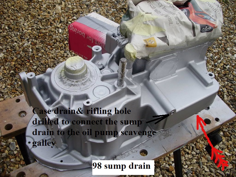 |  |
| 98 and Up Oil Pump Oiling Paths 84) |
 |