Table of Contents
This is an old revision of the document!
EVO: Transmission & Final Drive
Additional References:
REF section: 1998 1200S 5-Speed Transmission Inspection from XLForum Thread: http://xlforum.net/forums/showthread.php?t=1848977
1991-2003 5-Speed Constant Mesh Wet Clutch Transmission w/Trapdoor
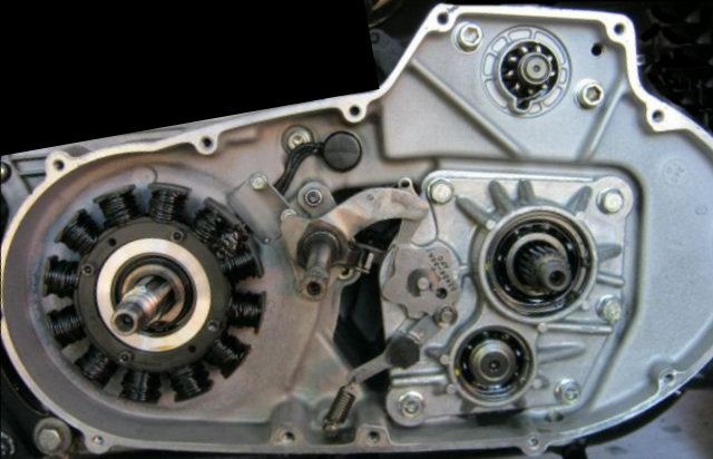
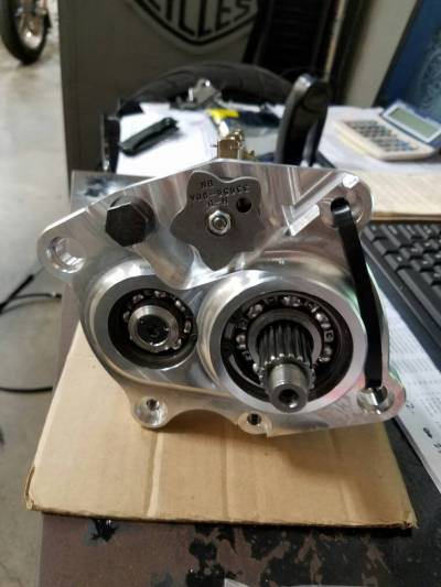
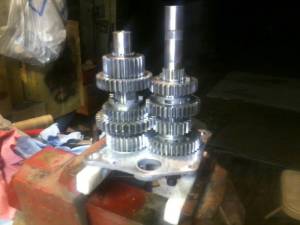
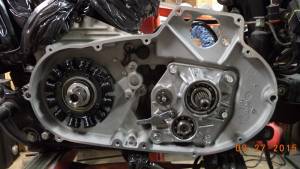
- The rear compartment of the left and right engine case halves form the transmission housing or case just as in the four speed. An access cover, or trapdoor, is mounted on the left side of the case (inside) behind the primary cover. The main components of the transmission are mounted to this trapdoor to allow you to detach the one cover (together with all the transmission components) for easy removal and servicing without having to split the engine cases in half which otherwise would be a full engine re-build.
(Click any picture to see a full-sized version)
 1)
1)  2)
2)
Overall Gearing is a ratio of the number of engine revolutions to drive the rear wheel one revolution. See the Gearing Chart in this section.
Primary / Transmission fluid capacity is considered 32 oz. (946 ml) when fully dry3) . However, it is typical to only need 28-30oz
when doing a typical oil change. Be sure to refill the cavity so that the level is just above the bottom of the clutch basket.
The Shifter Components (outside the trapdoor)
Shifter Assembly, Shaft, Pawl & Shifter Drum
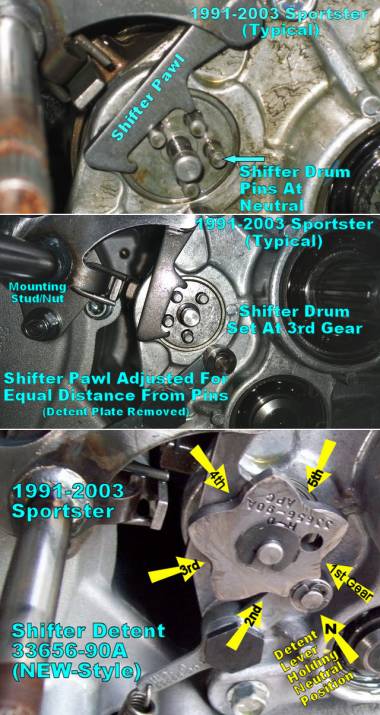
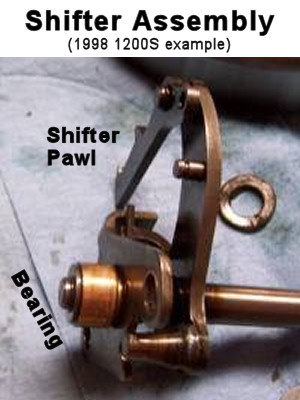
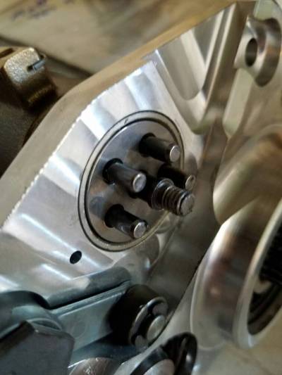
- The shifter shaft extends out through the primary cover. The foot shift lever is attached onto the shaft splines at the end. The shifter pawl is attached to the shifter assembly allowing the pawl to pull or push the rotating transmission shifter drum into gear as the shifter shaft rotates. In the detailed picture of the pawl, the shifter detent plate has been removed to show the pawl and the end of the shifter drum with it's four protruding pins. That picture shows the shift drum in the neutral position.
- When the primary cover is removed, the shifter assembly has significant motion (wobble) due to being supported at only one end. That end has the shifter bearing which has a relatively loose fit in its case cavity. When the cover is in place, the shifter shaft protrudes thru the cover bushing and stablizes the shifter assembly position. (See the GIF action image in post#1 of this XLForum thread: http://xlforum.net/forums/showthread.php?t=2077016)
- The shifter drum pins are an issue. Due to the engine heat cycles and the constant push and pull by the shifter pawl, the drum pins tend to come out (somewhat) from their mounting holes, causing the detent plate to skew from perpendicular. This causes stress on the detent plate retaining clip and causes excessive wear on the detent plate due to the skew. Whenever the shifter assembly is accessible, these pins should be homed into the shifter drum with a minimal tap on them with a hammer & punch.4) The pins should have an installed height of (.326“ - .334”). 5) If you find the pin height outside this range, replace the pins or the shift drum as necessary. (Read more here: XLForum Thread, Starting at Post#172 - http://xlforum.net/forums/showthread.php?t=2078814&p=5887502&postcount=172)
- The factory manual procedure for adjusting the shifter pawl recommends using a #32 drill bit in the alignment hole of the detent plate. Many have had issues when using this procedure, so understand that the goal is to place the shifter pawl such that it is an equal distance from the pins when the shifter drum is in 3rd gear. This can be accomplished with the detent plate removed. Loosen both shifter shaft assembly mounting nuts from their studs. Then rotate the shifter shaft assembly until the pawl is in the right location. Then partially tighten the lower nut, then tighten the upper nut, then finish tightening the lower nut. Make sure the final location is accurately set. This centering is critical to create accurate gear shifts. See these threads for more discussion - http://xlforum.net/forums/showthread.php?t=29016 and http://xlforum.net/forums/showthread.php?t=1556767.
Shifter Detent Plate, Lever & Spring
- The detent plate establishes the proper position of the shifter drum to keep the transmission in a particular gear, as well as to define the neutral position. The detent lever (arm) roller lodges between the lobes of the detent plate to resist slipping out of gear or neutral.
- The original detent plate was upgraded in 1999 (to P/N 33656-90A) to provide a more certain engagement of the gears and to make the neutral location easier to find. It is backward compatible. 6)
- Due to the above mentioned shifter drum pin issue, the OEM spring clip (P/N 11019) is sometimes replaced with an E-clip and a thin washer in order to help the detent plate keep those pins in place.7)
| Part Description | 1991-1993 P/N | 1994-2003 P/N |
|---|---|---|
| Shifter Shaft | 34015-91 | |
| Primary Cover | 25430-89A+ | 25430-94A+ |
| Shaft Bushing | 40520-63 | |
| Shaft Oil Seal | 11000101++ | |
| Shaft Washer | 7019 | |
+__latest P/N
++_latest P/N is 11000101 with 'garter spring' inside (old P/N 37101-84/A/B - no spring). Dims per James Gasket - 13 x 19 x 4
… Cometic Equiv of 11000101 is C10213
- Another idea to install the detent plate, is to thread the end of the shaft, then use a nut with blue Loctite. 8)
(Click any picture to see a full-sized version)
The Shifter Shaft Seal
Install On all models:
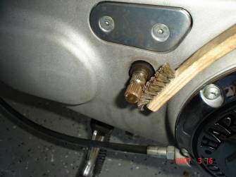
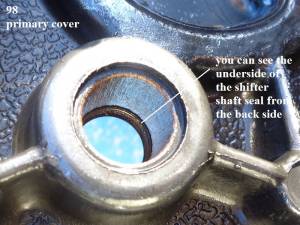
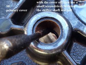
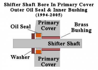 The oil seal can be removed without removing the primary cover - remove the lever, then use a pick or screwdriver to pry the seal out of the cavity.
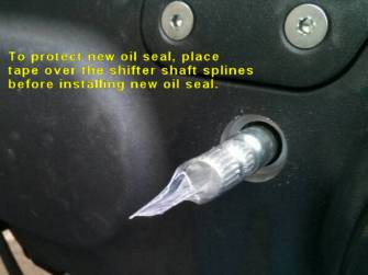
On installs, make sure the shaft is free from debris or rust and be sure to put tape over the splines on the shifter shaft before installing the oil seal to prevent the splines from cutting the seal.
The Oil Seal is installed first, followed by the washer/spacer.
For 1986-2005, the new shifter shaft oil seal is P/N 11000101. It replaces P/N 37101-84B.
NOTE: There is a TSB (M-1350) related to the 'NEW' Shifter Shaft Seal P/N 11000101 being installed with Special Tool HD-51337. The new seal has a 'garter spring' to help seal the shifter shaft from leaks. In this TSB, the following caution is made: If the tool is not used, install seal to a depth of 0.125-0.135 inches. DO NOT bottom the seal in the bore. This allows the spring to keep the lips of the seal against the shaft. Bottoming the seal will damage it and prevent it from sealing properly.
(While this TSB refers to Big Twins with 6-spd transmissions, this shifter shaft seal is used on other models, including the Sportsters.)
The idea is that if you bottom the seal, the lips around the shaft will be pressed tightly against the primary cover and will not allow the lips to smoothly follow the movement of the shaft. Thus, the tight lips will be thwarting the 'sealing' aspect that the 'garter spring' is designed to enhance.
The clearance should be from the deepest edge of the seal cavity in the primary cover. The referenced instructions are for the BT models. Therefore, the Sportster models may not be exactly the same.
BUT, the principle still applies: Insert the seal slightly below that deepest edge of the cavity and don't bottom out the seal. That gives it the best chance to work correctly.
To increase the tightness of the oil seal (as often suggested by SportsterPaul), after installing the rubber washer, you might install one or two o-rings to take up the gap between the shift lever and the washer. The o-rings do not seal against leaking oil but, instead, they put additional pressure on the oil seal in the primary cover cavity, which may help if you have a leaking seal. (But be sure you are installing the seal correctly as mentioned above, not bottoming in the bore.)
A couple ways of removing the seal:
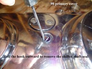 9)
9) 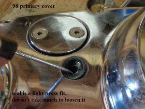 10)
10) 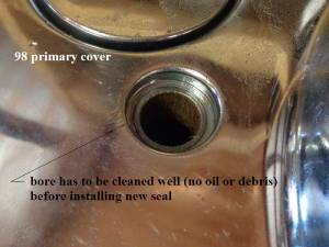 11)
11)
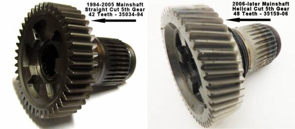
Mainshaft Fifth Gear
1991-E1994 Mainshaft 5th Gear, Bearing & Spacer
- 35034-89A - Gear Includes Needle Bearings
- 8996A - Ball Bearing (older P/N 8996 obsoleted)
- 33344-85 - Drive Sprocket Spacer
L1994-2005 Mainshaft 5th Gear, Bearing & Spacer
- 35034-94 - Gear Includes Needle Bearings
- 8996A - Ball Bearing
- 33344-94 - Drive Sprocket Spacer
Replacing the Case Bearing for the Mainshaft Fifth Gear
See this thread: http://xlforum.net/forums/showthread.php?t=766754
Final Drive (Trans to Wheel)
| Final Drive Sprocket Torque | |||||
|---|---|---|---|---|---|
| Nut Description | Nut Size | Tightening Torque | Notes | ||
| 1991-92 Chain | 1-7/8“ Nut - Left-hand Threads | 110-120 ft-lbs | Max 150ft-lbs | ||
| 1991-94 Belt | 1-7/8” Nut - Left-hand Threads | 110-120 ft-lbs | Max 150ft-lbs | ||
| 1995-03 Belt | Tighten to 50ft-lbs, then add 30°-40° more rotation | ||||
| (use only 2 or 3 drops of RED threadlocker on this nut) | |||||
| Be sure to use a sprocket locking tool when removing or installing the Sprocket Nut | |||||
| Year | 883 Model(s) | Transmission Sprocket | Rear Wheel Sprocket | Secondary Drive Belt | Ratio |
|---|---|---|---|---|---|
| 1991-1992 | 883 & 883 Hug (chain)14) | 21 Teeth | 48 Teeth | Chain driven | 2.29:1 |
| 1991 | 883 Deluxe15) | 27 Teeth | 61 Teeth (Belt) | 127 Teeth (yellow) | 2.26:1 |
| 1992 | 883 Deluxe16) | 27 Teeth | 61 Teeth (Belt) | 128 Teeth (orange) | 2.26:1 |
| 1993-2003 | 883 all models | 27 Teeth | 61 Teeth (Belt) | 128 Teeth (orange) | 2.26:1 |
| Year | 1200 Model(s) | Transmission Sprocket | Rear Wheel Sprocket | Secondary Drive Belt | Ratio |
| 1991-2003 | 1200 all models | 29 Teeth | 61 Teeth (Belt) | 128 Teeth (orange) | 2.10:1 |
See damage from loose Belt Drive Sprocket
XLForum Thread: http://xlforum.net/forums/showthread.php?t=767676
XLForum Thread: http://xlforum.net/forums/showthread.php?t=966388
Clutch
| 1991-1994, 1998 Wet Clutch Information 17) 18) 19) | ||
|---|---|---|
| Clutch plate thickness | Friction plate (fiber) | 0.0866 in. (± 0.0031 in.) / (2.200 mm ± 0.079 mm) |
| Steel plate | 0.0629 in. (± 0.0020 in.) / (1.598 mm ± 0.51 mm) | |
| Maximum allowable warp-age | –Friction (fiber) plate | 0.0059 in. / (0.150 mm) |
| –Steel plate | 0.0059 in. / (0.150 mm) | |
| Clutch pack service wear limit | 0.6610 in. min. / (16.787 mm) | |
Primary Drive (engine to transmission)
Transmission Gearing
- Internal Gear Ratios are the number of clutch gear revolutions to drive the mainshaft sprocket one revolution.
- Overall Gear Ratios are the number of engine revolutions to drive rear wheel one revolution.
| Year | Internal Gear Ratios | ||||
|---|---|---|---|---|---|
| US Models | 1st | 2nd | 3rd | 4th | 5th |
| 1991-1992 All Models 23) | 2.78 | 2.03 | 1.49 | 1.22 | 1.00 |
| Year | Overall Gear Ratios | Year | Overall Gear Ratios | |||||||||
|---|---|---|---|---|---|---|---|---|---|---|---|---|
| US Models 883 24) 25)26) | US Models 1200 27) 28)29) |
|||||||||||
| 1st | 2nd | 3rd | 4th | 5th | 1st | 2nd | 3rd | 4th | 5th | |||
| 1991-1992 883, 883 Hug | 10.16 | 7.41 | 5.44 | 4.45 | 3.66 | 1991-1994 | 9.35 | 6.82 | 5.01 | 4.09 | 3.36 | |
| 1991-1992 883 Deluxe 1993-1994 883 (All) 30) | 10.04 | 7.32 | 5.38 | 4.39 | 3.61 | |||||||
| 1998 883 | 9.71 | 7.12 | 5.18 | 4.26 | 3.61 | 1998 1200 | 9.04 | 6.62 | 4.82 | 3.97 | 3.36 | |
| Year | Overall Gear Ratios | Year | Overall Gear Ratios | |||||||||
| HDI Models 883 31) 32) | HDI Models 1200 33)34) |
|||||||||||
| 1st | 2nd | 3rd | 4th | 5th | 1st | 2nd | 3rd | 4th | 5th | |||
| 1993-1994 883 | 9.71 | 7.12 | 5.18 | 4.26 | 3.61 | 1993-1994 | 9.04 | 6.62 | 4.82 | 3.97 | 3.36 | |
| 1998 883 | 9.71 | 7.12 | 5.18 | 4.26 | 3.61 | 1998 1200 | 9.04 | 6.62 | 4.82 | 3.97 | 3.36 | |
| Year | Overall Gear Ratios | Year | Overall Gear Ratios | |||||||||
| HDI Swiss Models 883 35) | HDI Swiss Models 1200 36) |
|||||||||||
| 1st | 2nd | 3rd | 4th | 5th | 1st | 2nd | 3rd | 4th | 5th | |||
| 1993-1994 | 9.05 | 6.60 | 4.85 | 3.96 | 3.25 | 1993-1994 | 8.43 | 6.14 | 4.51 | 3.68 | 3.03 | |
Fastener Torque Specs
1991-1994 Torque Specs
| Transmission sprocket nut locking screws37) | |
| 1991 models (1 screw)38) | 50 - 60 in. lbs |
| 1992 chain drive models (1 screw)39) | 50 - 60 in. lbs |
| 1992 belt drive models (2 screws)40) | 7 - 9 ft lbs |
| 1993-1994 models 41) | 90 - 110 in. lbs (10.2 - 12.4 Nm) |
| Transmission sprocket nut (Caution left handed threads)42)43) | 110 - 120 ft lbs (149 - 163 Nm) |
| Access door / trapdoor bolts44)45) | 13 - 17 ft lbs (18 - 23 Nm) |
| Engine sprocket nut (right hand threads)46)47) | 150 - 165 ft lbs (203 - 224 Nm) |
| Clutch hub nut (Caution left handed threads)48)49) | 70 - 80 ft lbs (95 - 108 Nm) |
| Sprocket cover screws50)51) | 90 - 110 in. lbs (10.2 - 12.4 Nm) |
| Drain plug52)53) | 14 - 21 ft lbs (19 - 28 Nm) |
| Primary cover screws54)55) | 80 - 110 in. lbs (9.0 - 12.4 Nm) |
| Primary/ transmission lubricant level screw56)57) | 90 - 110 in. lbs (10.2 - 12.4 Nm) |
| Chain tensioner stud nut58)59) | 20 - 25 ft lbs (27 - 34 Nm) |
| Stator Torx fasteners60)61) | 30 - 40 in. lbs (3.4 - 4.5 Nm) |
| Neutral indicator switch (91-92)62) | 3 -5 ft lbs |
| Shift lever pinch bolt63)64) | 90 - 110 in lbs (10.2 - 12.4 Nm) |
| Footrest fasteners65)66) | 16 - 28 ft lbs (22 - 38 Nm) |
| Clutch release mechanism screws67)68) | 22 - 30 in lbs (2.5 - 3.4 Nm) |
| Inspection (Derby) cover screws69)70) | 40 - 60 in lbs (4.5 - 6.8 Nm) |
| Countershaft retaining screw71)72) | 13 - 17 in lbs (18 - 23 Nm) |
1998 Torque Specs
| Sprocket nut lock-plate screws73) | 90-110 in-lbs / 10.2-12.4 Nm |
| Sprocket nut (caution - left handed threads)74) 50 ft-lbs. (67.8 Nm) initially Tighten an additional 30-40 degrees Install lock plate over sprocket nut to align to two opposite threaded mounting holes Tighten sprocket nut additionally if holes don't match up but not to exceed 45 degrees total |
|
| Sprocket cover screws75) | 90-110 in-lbs. (10.2-12.4 Nm) |
| Access / trapdoor bolts76) | 13-17 ft-lbs. (18-23 Nm) |
| Engine sprocket nut77) | 190-210 ft-lbs. (258-285 Nm) |
| Clutch hub nut (caution- left hand threads)78) | 70-80 ft-lbs (95-108 Nm) |
| Countershaft retaining screw79) | 13-17 ft-lbs (18-23 Nm) |
| Oil Drain plug80) | 14-21 ft-lbs. (19-28 Nm) |
| Primary cover Allen Head screws (1/4“x 20 threads)81) | 80-110 in-lbs. (9.0-12.4 Nm) |
| Primary chain tensioner stud82) | 20-25 ft-lbs. (27-34 Nm) |
| Stator Torx Head screws(1/4”x 20 threads)83) | 30-40 in-lbs. (3.4-4.5 Nm) |
| Shift lever pinch bolt84) | 90-110 in-lbs. (10.2-12.4 Nm) |
| Clutch inspection (Derby)cover T-27 Torx Head screws85) | 40-60 in-lbs. (4.5-6.8 Nm) |
| Footrest Allen Head bolts (5/16“x18)86) | 16-28 ft-lbs. (22-38 Nm) |

