Table of Contents
This is an old revision of the document!

IH: Carburetor, Intake Manifold & Exhaust - Sub-01C
Bendix Zenith I6P12 Carb (1972-Early 1976)
See also in the Sportsterpedia:
Bendix Carb Rebuilding / Refreshing
If you placed the plunger in the Taiwanese rebuild kit next to the stock part, the Taiwanese part is much longer.
This in turn can cause the plunger to 'bottom' in the bowl and it can get stuck as in when at W.O.T.
It actually can bottom before the butterfly is fully opened.
You can use most of the parts in this kit but purchase the Harley Part (#27762-71TA).
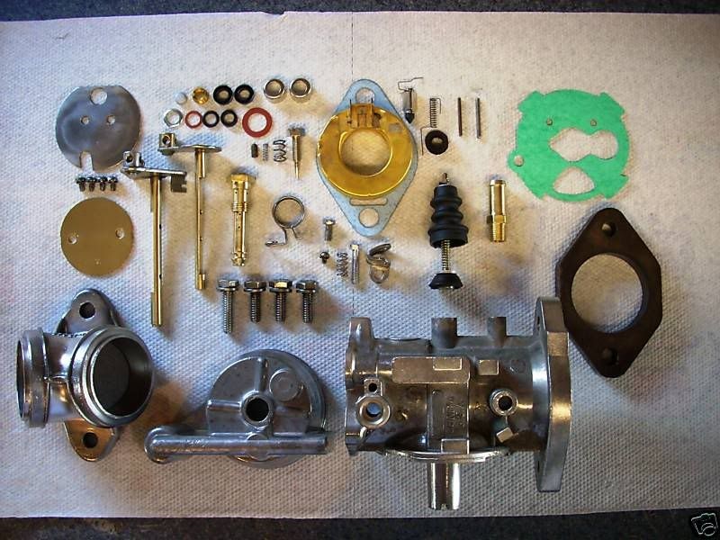
Aftermarket rebuild kit:
 1)
1)
Cleaning
- The general appearance of the inside of the carb is not necessarily a good indication of its condition.
It can look spotless and have clogged jets, or look cruddy and have clear jets. - It's good to clean each individual part rather than soak or boil the whole carb in carb cleaner.
But either way is good. Do not allow any solvents to contact any rubber parts (tip of needle, O-ring seal for bowl). - Make sure to take everything apart, jets, needle, accel pump, all rubber components especially.
- Examine all parts for excessive wear, damage, distortion, etc.
- Cleaning solutions/sprays vary based upon your location, needs, budget, preferences and quality.
Dismantle the carb down to the body before soaking. You will be surprised at all the dirt in the bottom of the soaking container.
Here are some helpful ideas:- An overnight soak in a solution of Pinesol and water followed up with a good brush down with a toothbrush then rinse and air dry. 2)
- A 20 minute to up to a few days soak in a gallon of Gunk (or other) Carburetor Cleaner that has a basket inside for small parts and lowers in the can with a handle, rinse, air dry, use.
- Soak it in mineral spirits for a few days. 3)
- You can use acrylic paint thinners for cleaning up carb parts. It melts the fuel varnish right off. 4)
- An aerosol spray carb cleaner will also work but may not loosen all of the build up in the jets or orifices in the carb body if they're not directly sprayed through.
- Blow out all holes, jets and orifices thoroughly with compressed air after cleaning.
A gallon of carburetor cleaner is very useful in cleaning out varnish from the channels and metering chamber.
It is especially useful for soaking stuck gaskets between parts and loosen the joint between them for dis-assembly.
Depending on how old or how 'stuck' the parts are, soaking for a couple hours may help to separate the old gasket in between.
Make sure to remove any rubber or plastic parts before soaking. Also check the label for safety precautions.
Parts that have been sitting for years may have to be soaked for about 24 hours or even days.
| Carburetor Cleaner 5) | |
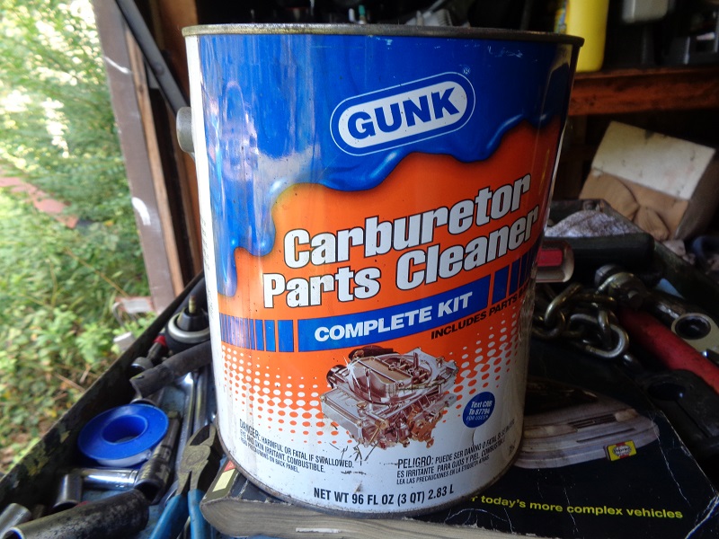 |  |
Note:
The use of wire to 'rod' out jets and orifices is discouraged in the FSM.
However, a hard wire such as a welding tip cleaner, has been known to open up stubborn areas at times.
Always use a wire smaller than the orifice cleaned so you don't widen the holes.
Doing so could create burrs or change the hole sizes.
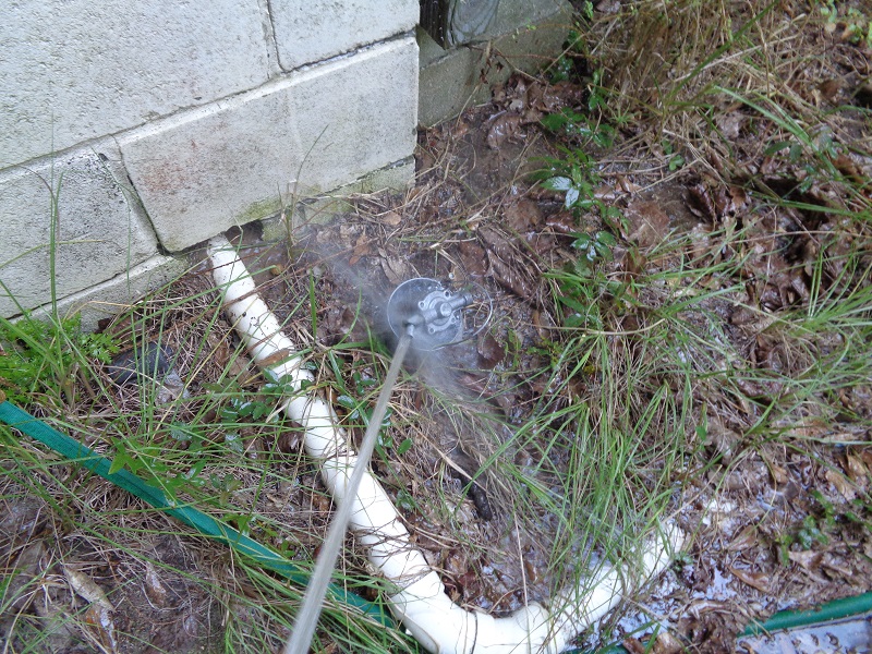
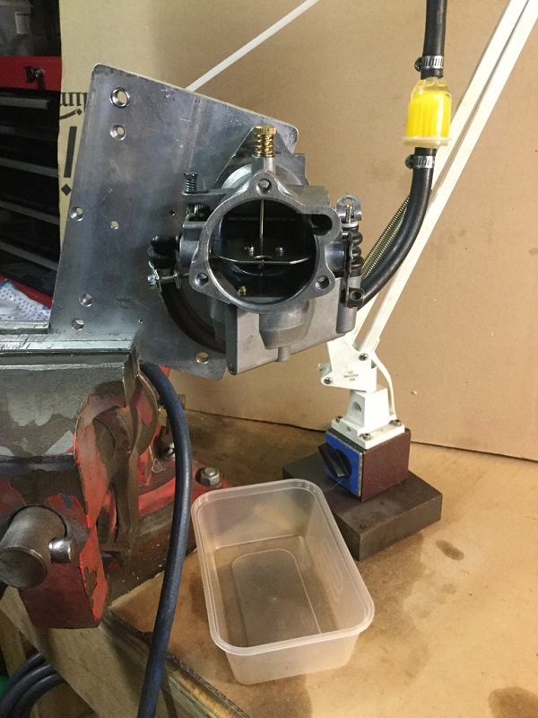
Carb Stand:
- You can put the carb in a vice to remove the screws, and for much of the following work.
Wrap in a shop towel; close the vice gently taking extra care with the choke and throttle linkages.
The vice is a needed extra pair of hands. - It can be very confusing trying to decide which way to bend the tang if it is not correct.
If the fuel level is low,Is the float high or low?, Do you need to bend the tang up or down? etc.
On the bench the carb is usually upside down, adding to the confusion. You should sort all this out before making an adjustments.
However, this setup works better than putting the carb directly into the vice.
The carb is set upright as 'in use' making adjustments more straight forward.
 6)
6)
 7)
7)
Main Jet / IdleTube
Main jet
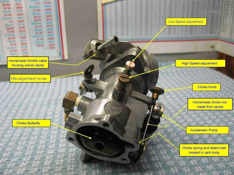
The main jet screw is the one closest to the air cleaner. The Idle screw is closer to the manifold.
The main jet doubles as the float bowl securing bolt under the carb.
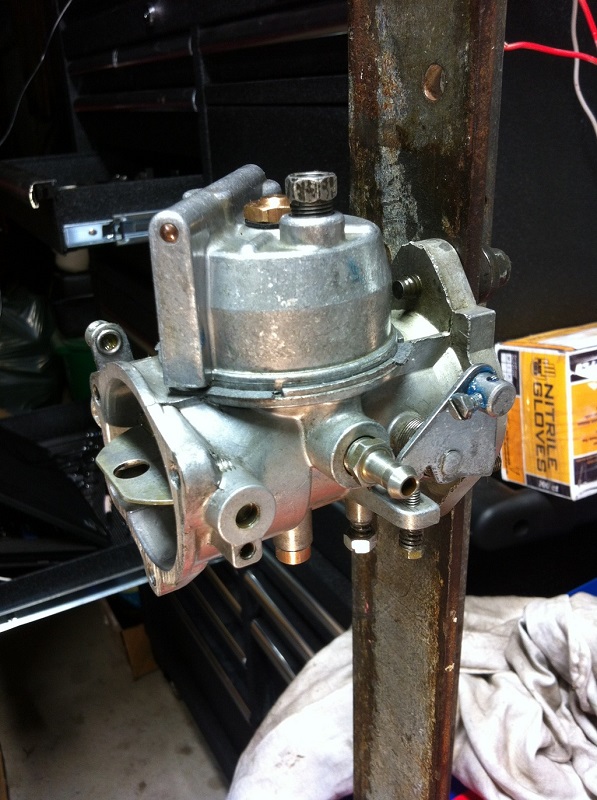
Fixed or adjustable main jet identification:
The factory Bendix carbs for Sportsters have a fixed main that doubles as the float bowl bolt with the Idle tube on top.
For a quick visual, look at the top of the carb, first screw boss from the A/C, look for either a welch plug or a screw head with no spring under it.
The screw head looks like it could be adjusted but it is not the adjustable type. 8)
The later 'Zenith' Carb with the adjustable main has a screw that goes thru a spring.
The spring is visible looking at the top of the carb, first screw boss from the A/C.
It is the main adjustment that has a tapered point at the end.
- Turning clockwise = leaner.
- Turning counter-clockwise = richer.
Adjustable main jet conversion
Sub Documents
Some say not to do this as an adjustable main jet is too easy to inadvertently lean out the mix too much and burn a piston or two. 9)
If your certain carb is suppose to have a fixed jet but has an adjustable jet instead, it may have been modded for the adjustable jet.
For the adjustable main jet modification, the kit describes cutting a thread in the hole where the welch plug normally goes. 10)
J&P sells the conversion kit. Adjustable Main Jet Kit for Bendix/Zenith Carbs
J&P Cycles Part Number: 401-817, Manufacturer Part Number: 35-0202
- Establishes full adjustability for Bendix and Zenith carb main and idle circuits
- No need to stock several and expensive fixed jets
- Requires special tap 400-966 for installation
- Kit includes main jet, fiber washers, idle jet and control spring
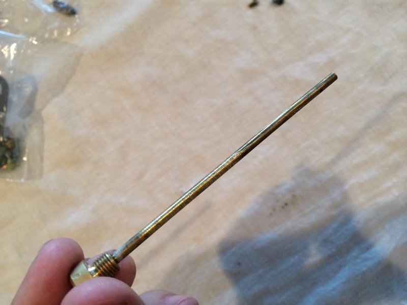
Idle Tube
Alternate references include intermediate / idle / low speed jet. The original idle tubes are designated with either
The “needle” is just a transfer tube to get low speed mix from the bottom of main up to the top side of the carb to the idle/low speed circuitry. 11)
The tube is a pretty sloppy fit where it enters the top of the carb, below the threads.
There is a built in air bleed circuit between the idle tube passage and idle mixture circuit.
It's location of the idle air bleed allows less fuel flow during time of open throttle plate high reversion compared to the other OEM carbs. 12)
Translation: it's the bleed that allows the Bendix to tolerate straights better.
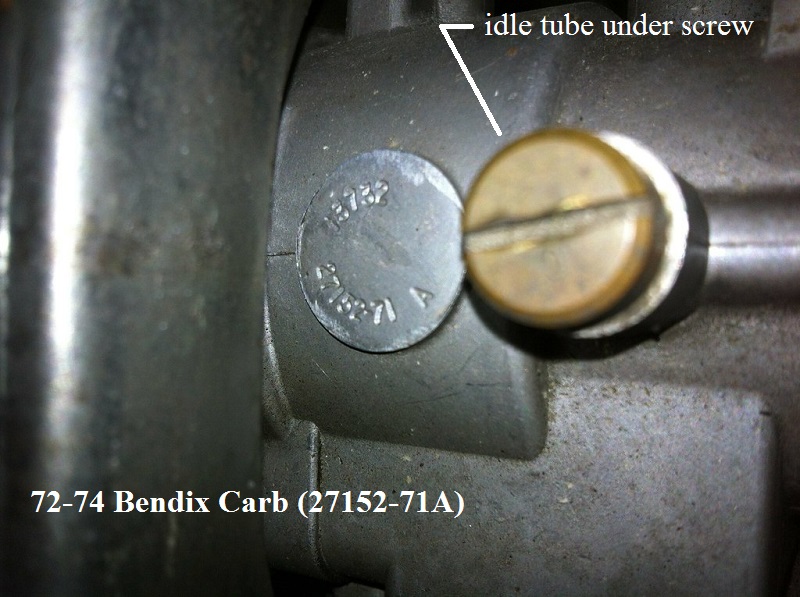
The Idle Tube on top of 72-74 OEM carbs is a brass flat top screw that screws thru a fiber washer down thru the top into that fixed main jet (all non adjustable).
From 1972-1974, the idle tube was exposed on top of the carb with a brass screw for installation.
 13)
13)  14)
14)
The idle tube on 75-E76 carbs is pressed into the body with a welch plug covering it.
Zenith/Bendix offered (and still does) aftermarket carbs with an adjustable main which replaced the brass idle tube (screw closest to the cleaner).
This screw in tube with the small spring actually doubles as an idle tube to pick up fuel up to the idle circuit.
But the taper at the end of it is to adjust the main circuit.
The size / markings / pilot orifice of the adjustable idle tube is not known. 15))
But you could use a pin gauge or drill bit to measure should you feel the need to work on this circuit.
Keep in mind the adjustable main's biggest job is it blocks or opens the main circuit with the taper at the end. 16))
The rest of the tube / orifice has nothing to do with that. That is for the low speed.
Like any adjustable jet, you cannot over tighten it clockwise or you can indent the taper.
The later adjustable main is favorable if mounting on an early magneto motor as you do not have to pull the carb off to make main adjustments.
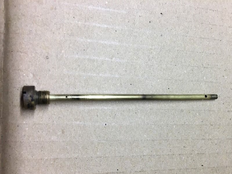
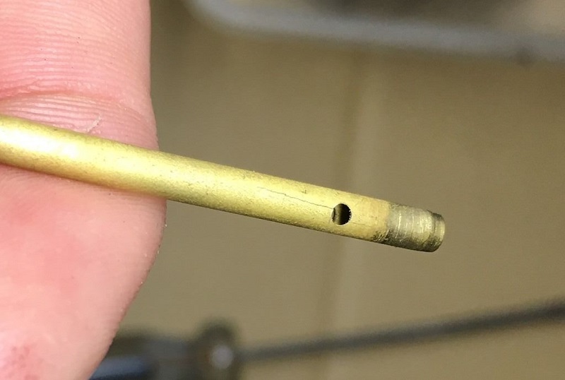
Check the idle tube for cracks. This one doesn't look cracked unless you look at it close up.
 17)
17)  18)
18)
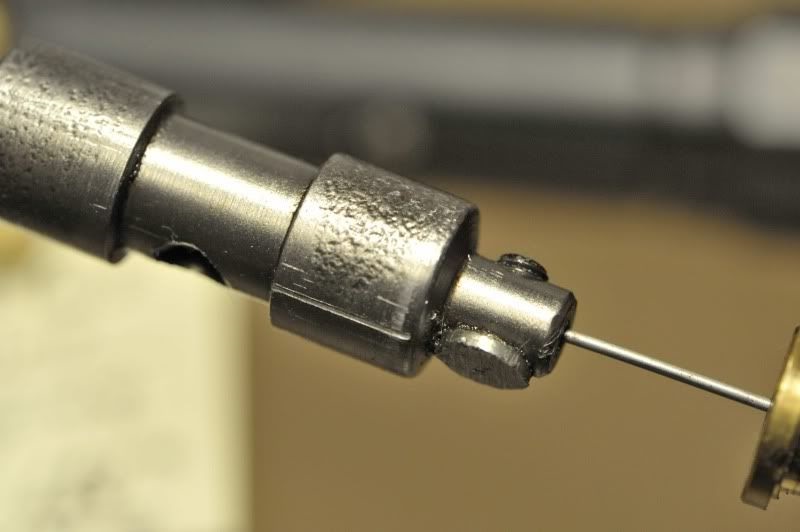
Accelerator Pump
There are 3 holes in the accelerator pump shaft to provide more or less fuel upon acceleration.
Install the pump shaft pin in the bottom hole for richest setting or the top hole for the leanest setting.
In some of the new kits, you may find the accelerator pump is slightly too long as in the pic below. 19)
The throttle could hang up at about 90% (the bracket mechanism might hang up on the shaft, if the shaft is too long).
Fortunately the solution is fairly simply. Take a dremel tool and trim the top about 1/16“ - 1/8” or so and bevel the edges.
Click on a pic to enlarge:
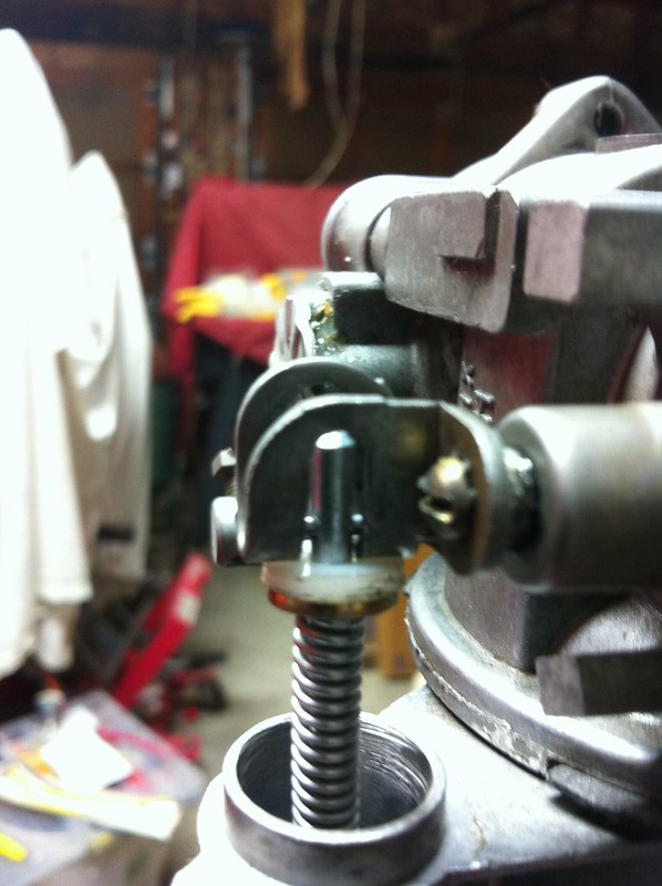
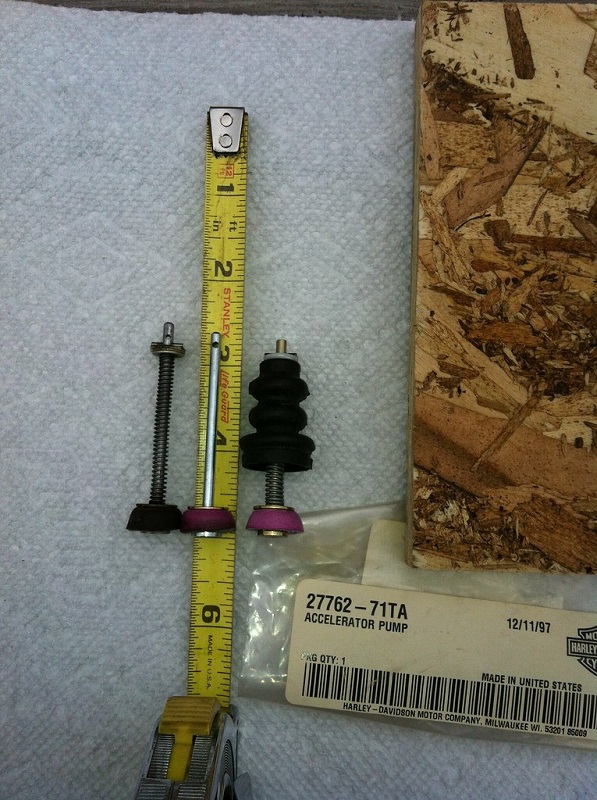
In the first pic below, the left one below is the original accelerator pump as it came from the factory in 1974.
Middle is from the new rebuild kit. On the right, is the accelerator pump (27762-71TA) as purchased from a local HD dealer.
The middle unit is the problem item. The upper section, the piece above the roll pin, is too long.
The second pic below is the after pic. The middle unit, has had the upper section of the shaft trimmed down. Good to go now.
Rub some oil onto the umbrella before installing it. 22)
This makes sure it sets itself instead of binding / deforming in the first few uses (also insures smooth operation).
Also look down inside the bore of the acc pump and make sure there isn't any residue scale.

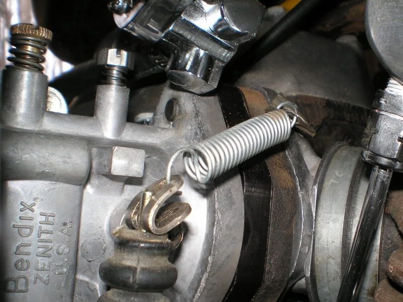
Add this spring to your accelerator pump if you don't have it. It will pull the butterfly closed when you let off and give the throttle a good feel.
 25)
25)
Welch Plug or Expansion Plug
- Inspection:
- A close inspection around the walls of a welch plug can reveal possible leaks.
- Removal: 26)
- Whenever a welsh plug is removed, a new one should be installed in it's place, especially since a large part of the time, removal of one means destroying or deforming it.27)
- Drill an 1/8“ hole thru it (just deep enough to break thru to the other side) off center and pry it out with a small punch. Be careful not to drill too deep which could destroy the nozzle assembly or casting. While prying it out, be careful not to damage the casting counter-bore edges around the plug.
- You can also drill a small hole in it and use a small tap just big enough to start in the hole. 28)
Thread the tap in the hole.
When it gets to the bottom of the passage, it will force the valve out with out damaging the bottom of carb passage.
Make sure to clean all the chips out to keep from plugging up passages later.
-
- The plug should be seated with a flat end punch that is slightly smaller than the diameter of the plug. The plug should be flat and not concaved to assure a tight fit. If leakage is suspected due to a rough or damaged welch plug seat in the casting, apply a small amount of epoxy or suitable sealant to the edges after installing it.
- Installation Recommendations from Hubbard Spring http://www.hubbardspring.com/install_reco.php?cid=45
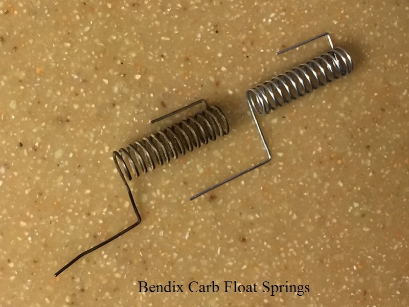
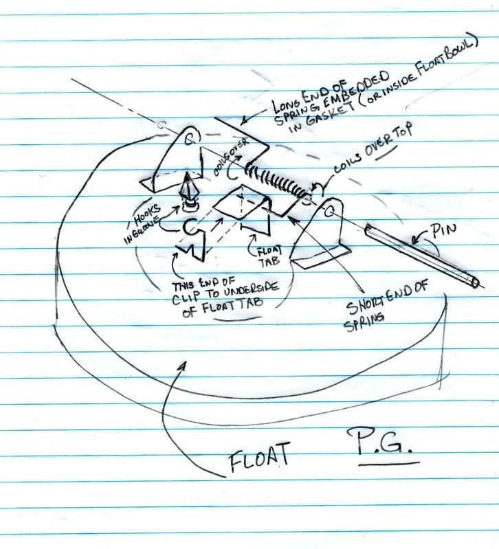
Float
Sub Documents
See also Installing Bendix Float Spring.
The spring should not be stretched or distorted.
Inspect the needle valve cone point for wear and scratches. 31)
Choke Plate \ Cable
Before cranking the engine, the throttle should be opened to expose all three idle holes (top inside the venture). 34)
The choke should be fully closed when cranking the engine and slightly opened after the engine starts.
The hole in the choke plate helps to prevent over-choking when the engine is started.
It should be moved to wide open when the engine is patially warmed up.
Here is a pic of what the installation of the choke/throttle butterfly looks like. The small hole/cutout is at the top. 35)
 36)
36)
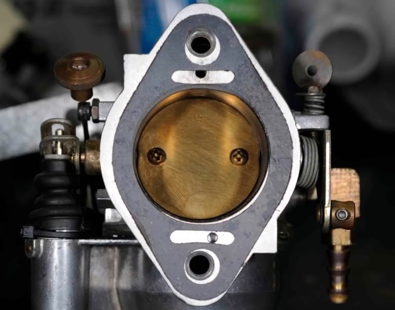
The throttle butterfly in the main body opens to the manifold. 37)
When it's shut, no throttle, you should be able to hold the intake side of the carb up to the light and not see anything around it showing light.
If it does, it's out of round and hard to fix as it leans out the mix.
Adjusting the choke cable:
Push the knob all the way in, have the choke wide open, tighten set screw on the cable. 38)
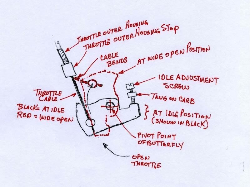
Throttle Cable
If you have a twist grip throttle (barrel type) you are not going to be able to use hard wire. The bellcrank on your carb makes the cable end swing in an arc.
You may want to bend the end of the bracket just a bit upwards to lessen the binding at closed throttle.
As you open the throttle the cable becomes more inline with the housing and binding becomes less and less.
The butterfly is going to go and stay where the cable tells it to go. 39)
The cable can bind with the hard wire throttle. The sketch below is exaggerated but it will give you a general idea of what can bind when the throttle is opened.
The cable is straight and the bell crank on the carb turns in a circular motion around the pivot point of the butterfly shaft.
 40)
40)
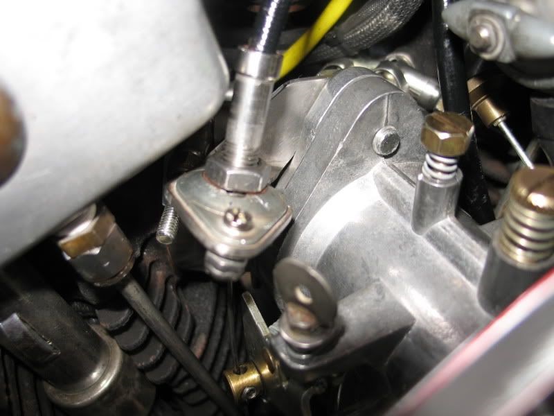
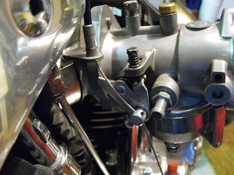
One solution was to fabricate a cable holder that was able to rotate slightly as the angle of the cable changed. 41)
This has a bronze ball inside the capping pieces which rotates as the cable moves around.
The bracket is mounted to the back side of the manifold (towards the center of the frame).
The ball is threaded and into that screws the cable housing stop fitting.
So as the angle changes, the ball swivels and so does the end of the cable housing allowing the cable not to bend or get pinched.
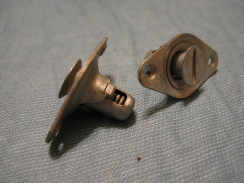
These were made out of a pair of Quik Fasteners. Two halves go around a round brass ball.
This allows the housing to rotate as the throttle is opened and closed.

Another simple way for the internal throttle setup: 45)
Fab a 90° bracket that is mounted off the top manifold bolt.
Then purchase an HD cable clamp (9994) and route the cable through the left side and adjust so that its inline with carb swivel.
The 9994 is the same factory clamp as used for a magneto cable (disregard the spring shown, it's not needed)

If you're using a braided cable, it needs a return spring on the butterfly. If you do not, then that will result in high revs when you blip the throttle. 48)
The hard wire is what opens and closes the butterfly. The braided cable cannot close the butterfly because the cable is not stiff enough.
Even if you find broken strands, be sure to rig up a spring. It wont take a great deal of spring tension to close the butterfly, but a spring is needed.
If the cable is that shot, replace it. But if just the ends are frayed, you can solder them together with electronics solder. 49)
Start by cleaning it with alcohol (cleans great and leaves no residue). 50)
After this if it is frayed get some small wire (30 AWG). Use this to wrap the end of your cable so all of the strands are contacting each other.
(gets rid of the birdcage look). Apply flux, add heat and solder.
When the solder flows into the strands remove the heat, let it cool and remove any excess solder with a file.

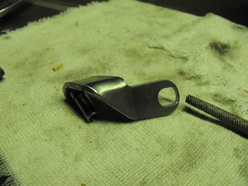
Below, the existing bracket was modified. With two crescent wrenches and a rat tail file, the hole was enlarged almost to the end of the support. 53)
Make sure to get it out far enough to clear the throttle shaft cam. The bracket was put in a vise and to bend the very end up and in to about 45°.
Using the two crescents, one on each side of the cable sleeve, it and just rolled it back.
Be careful not to pry / push on the cable sleeve. It's only rolled over on the bottom like a rivet.
Next, the bracket was positioned in the vise and the cresents were used to open up the existing 90° bend another 45°.
You may have to tweek it a bit to get the straightest throw for the cable.

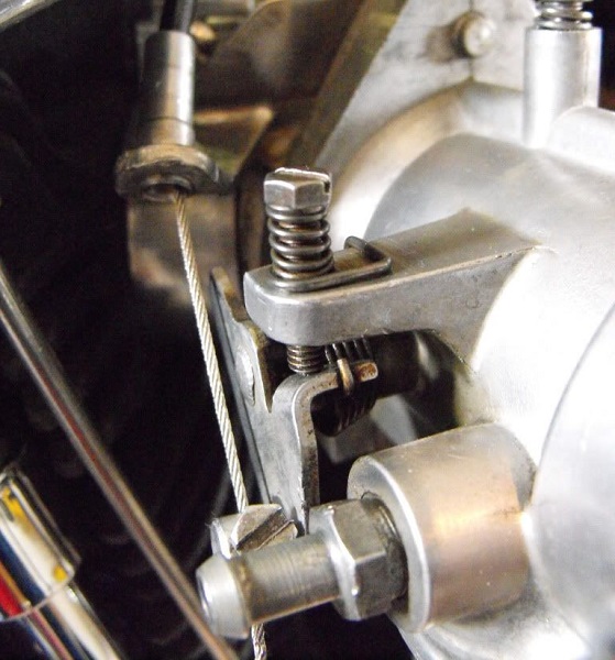
The single set screw on this cable assembly has nothing but the cable to tighten against.
A single screw to clamp the cable not only kinks it, but also causes the braid to separate somewhat.
This mod was done to be able to clamp the cable and minimize damage to the cable.
If you used a set screw on either side of the cable, both would tighten on the cable and keep it more centered.
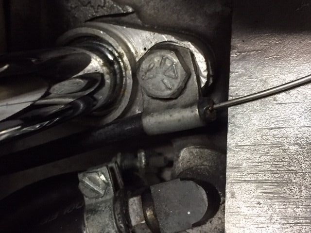
The cable below is a hard wire but may also work on braided cables if you have the room.
However, for this, a metal dowel was installed in the housing side opposite the set screw.
This allowed the set screw to tighten solid against something hard with the cable in between (same as a double set screw).
The dowel is on the bottom side and the set screw is on top side in the pic below.
 57)
57)
Carb Flange
There are 2 small holes in the carb to manifold flange (as viewed on the outside).
Those holes are factory drilled as part of the manufacturing process and serve no further purpose. 58)
When mounted against the manifold, they would be blocked anyway.
The small hole was used for cross drilling the air runner boss then through drilled from the top of body for the idle mixture screw.
Some flange gaskets have cutouts for these holes and some do not. Don't worry about them as you can use either gasket. 59)
The gasket producer more than likely had a carb body to use for a guide when making the gaskets.

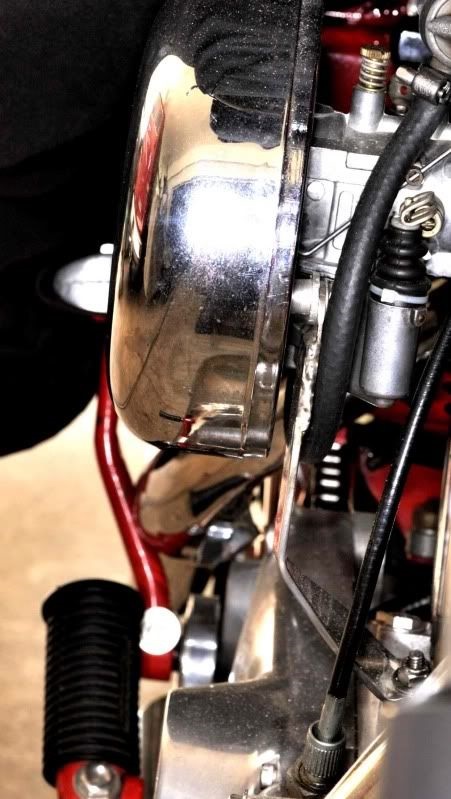
Carb / A/C Brace
The simple way to add the needed support of the carb is to use a metal brace from the A/c backing plate to the front intake lifter bolt stud at the bottom.
You can make your own bracket out of 1/8”x3/4“ steel or aluminum, bent and drilled for a hole to bolt it down by the bottom of the lifters.
Just drill the backing plate with a 1/4” drill bit and attach the carb bracket with a 1/4“-20 nut and bolt with washers.
For the bottom of the carb bracket you can do no better than using the 'studded' lifter base bolt.
You can make the carb bracket as a simple item or make it more complex if that suits you.
This is commercial carb brace. The angle was slightly modified on this one to fit.
 62)
62)  63)
63)
This one is made from an 1/8”x3/4“ stainless steel strap. It has an aluminum spacer block between the backing plate and the brace at the top.
 64)
64)  65)
65)
Mounting an Air Cleaner
The weight of the air filter is irrelevant. All models need an air filter support. 66)
The manifold to head joints were never intended to support anything, and do a poor job of it.
All bikes came from the factory with a support, the later bikes have 2.
NOTE:
There are some aftermarket supports that pick up a carb mounting bolt but they don't hold up the air filter and they act as a teeter totter.
Tuning
Stock Bendix (fixed jet) Tuning
Before making any adjustments, bring the engine up to operating temperature. 67)
Make sure the air filter is clean and that there is no leaks in the carb to manifold connection.
Low speed needle:
Turned in (clockwise) will lean the mixture.
Turned out (counter-clockwise) will richen the mixture.
The needle valve is held in position by a spring.
Adjustment:
Turn low speed mixture screw all the way in (clockwise) until lightly seated (do not tighten). Then;
(72-73) Back it out (counter-clockwise) 1-1/2 turns.
(74-E76) Back it out 2-1/4 turns.
With the needle in this position, the engine will start but the mixture will be rich.
Throttle lever stop screw:
Adjust throttle lever stop screw to the engine idle at desired speed with the throttle fully closed.
(Clockwise makes engine run faster, counterclockwise makes engine run slower.
Never set idle adjustment to slowest possible speed.
An extremely slow idle causes bearing wear oil consumption and slow speed acceleration problems.
Final adjustments:
Make final low speed needle adjustment after engine is at operating temperature (first in then out to see if the engine picks up smoothly).
Starting and all around operation will be better when the mixture is slightly rich.
If necessary, go back to the idle stop screw and readjust, then back to the low speed needle.
Recommended idle speed is 700-900 RPM.
During high speed operation, the fuel is metered by the fixed jet which has no adjustment.
Aftermarket Bendix (adjustable main jet) Tuning
One advantage of using an adjustable main is being able to tune without removing the carb. 68)
The float bowl won’t come off without removing the carb when running a magneto.
Instructions per the “C194-19 Zenith Model 16p12 Installation Sheet (with adjustable main jet)”. 69)
As a replacement for Keihin or older Bendix, Tillotson carbs:
- Mount it in place of old carb using the proper studs and mounting hardware.
Install the vacuum tube (if applicable) or plug it off. - Connect the throttle, choke and fuel line.
- Use an inline fuel filter to minimize contamination if you don't have a screen on the petcock.
- Install the air cleaner.
Note: If using the chrome plated 40mm carb (014052);
- There is an overflow tube included with the kit.
The overflow tube should run away from the exhaust to the front of the bike.
You can use the existing overflow tube setup (if equipped) but check for cracks and holes in it. - A new choke cable bracket and cable/knob assembly for installation on 86-87 Sportsters (available in the c182-1387 accessory kit).
Be sure to install the choke cable with the choke in the open or normal running position.
When your sure of operaton, cut the excess wire off the end of the cable. - You may need a set of spacers to install the stock air cleaner on 86-87 models. They are included in the accessory kit.
Air cleaner screws should be tightened in sequence, alternating each screw until completely tightened. - If using the chrome plated 40mm carb (014052) on 1340cc engines;
Yyou may need a jet discharge tube (c66-184-2) added to eliminate a lean condition even with the main jet in the full open position.
Initial carb settings:
- Open the idle adjustment (low speed) needle 1 full turn open (or out) from fully closed.
This needle is on top of the carb closest to engine.
Now adjust the main jet (high speed adjustment) out app. 4 turns open (or out).
The lowest (or closed) position occurs when the tension spring is coil bound (but not tight). - Start the engine and check for leaks.
Adjust the idle mixture screw until you obtain the highest and smoothest possible idle.
Adjust the overall idle speed with the idle stop screw on the throttle lever. - With the idle speed and mixture adjusted, high speed mixture can be adjusted by running the engine up thru first or second gear to 4500 RPM or above.
Overly rich mixture responds by breaking up or running roughly at high RPM.
To lean out the main jet, turn the main jet adjustment needle in app. 1/2 turn at a time until the engine responds by pulling cleanly through high RPM ranges in 1st or 2nd gear.- However, the only way (short of a dyno) to tell is to run the bike to redline in top gear. You can't tune a main jet while the bike is on the side stand. 70)
- After the high speed mix is adjusted, it may be necessary to slightly re-adjust the idle mixture screw.
- Changes in cams, exhaust or engine displacement may require idle or main jet re-adjustments.
But the range of adjustments should be enough to accommodate a wide variety of engine sizes and modification levels. - Extreme caution should be used when handling fuel or making adjustments.
Do not make adjustments on a moving motorcycle.
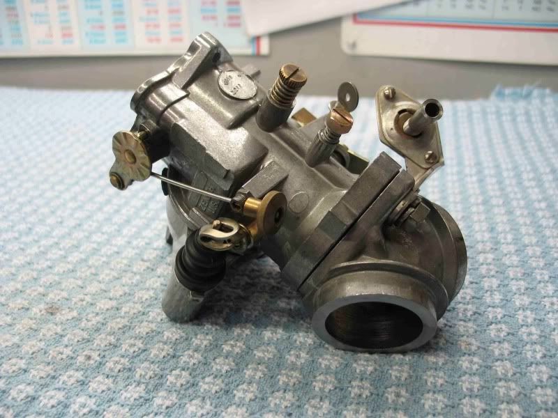
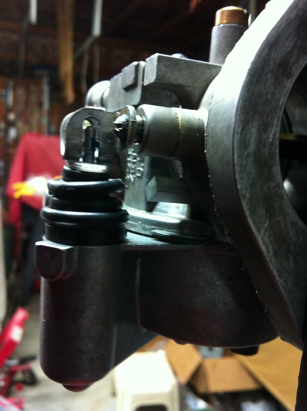
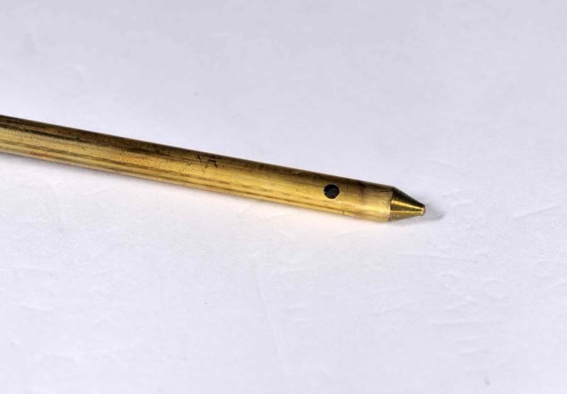
Here is the adjustable needle. It has a spring (at the top end) to keep tension on the needle.
The pic to the right is of the bottom end of the adjustable main jet needle (installed). Notice how close it comes to the absolute bottom of the float chamber.
Also notice that this particular bowl has no drain plug like the one shown in the factory manual.

Troubleshooting
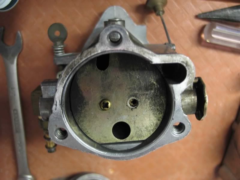
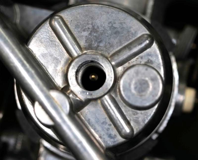
Flooding
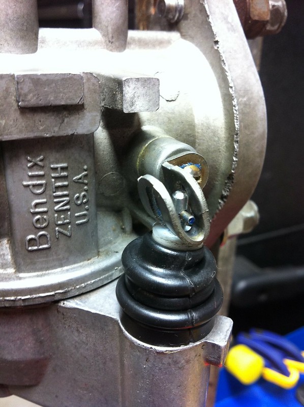
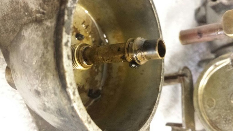
Excess fuel should be coming out of the hole in the pic below and the cause is either a too high float level or a stuck / blocked float needle failing to seat.
- Check the float level setting and adjust to 3/16 inch if needed.
If it pukes fuel after you set the float correctly, then just buy a new float needle and it will come with a new seat.
Replace both of these and you should have no more fuel puking. - When you install the float bowl back on you will have to take the end of the float spring and wrap it upwards as you install the bowl.
This end of the spring has to be inside the bowl and resting against the wall of the bowl. - No need to put the carb back on the engine yet.
Just hook up the gas line from the tank and holding the carb level turn on the petcock.
If the needle is seating, no excess fuel should come out the overflow.
If it does, tap the side of the bowl with a wrench to dis-lodge the needle.
If that does not stop the flow, then you need to buy the kit and replace the needle and seat which come as a matched set. - Some of the rebuild kits have the wrong size needle, it is too big. Compare it to the old one to see if they are different. 76)
- Also check the needle seat for dried varnish or debris, out of round or damaged,
- Make sure the float is moving free and easy, with no sticking. It should take no force whatsoever to move the float up and down.
- Also, check to see if your float, floats. Submerge it in a container of water to check for leaks.
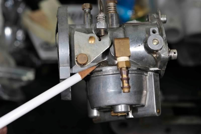
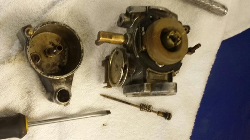
Here is where the overflow hole is located at (left pic, pencil points out the hole). Carefully take the carb apart.
Watch out not to tear the gasket, or else you will need the kit (the gasket is normally very durable).
The only gasket you will find is the one on the float bowl. The right pic below shows what the gasket looks like with the float removed.

Running Rich
Running super rich and fouling the plugs even at highway speed.
The bike would start up easy and after about 20 miles down the road, the plugs would foul.
Pulled the plugs and both were sooty black.
One plug would remain firing but the other cylinder was dead.
The problem was inside the carb.
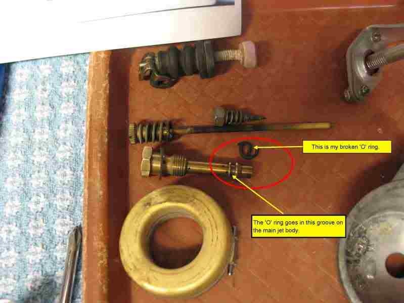
There is an O-ring around the main jet body that had degraded and broken in half.
This allowed raw fuel to leak directly into the inlet manifold rather than be routed through the main jet.
With a 10 pack of #5 O-rings ($1.29) from the hardware store plumbing department, the carb was fixed.
Sometimes when you push the main jet into the body attaching the bowl, the O-ring rubs on the threads of the body and can “clip” a piece out of the O-ring. 80)
You can use dielectric grease to lubricate them, and they slide right in.
If it clips the O-ring, the main jet will allow the fuel to bleed into the throat causing flooding, hard to make idle, and almost impossible to increase the rpms.
On the needle valve clip, if you run them towards the air cleaner, they seem to work better and not hang up, but i always clip mine a shade shorter, so they won't spin and get tangled up in the float.
High throttle on startup
Look at the throttle butterfly when you begin to start it.
The butterfly should be tight against the idle screw when the throttle is rolled off. There is no way the revs can be high if the throttle is closed.
There is nothing in the carb or anything that you could do (or fail to do) with reassembly other than install the throttle butterfly upside down. \
The throttle butterfly plate should close off the venturi when you roll the throttle off.
Take a look inside the open end (A/C end of the carb) to check this.
Most of the time high throttle on start up is the result of the throttle cable holding open the butterfly.
The main needle adjustment will have no effect on this either. It only comes into play at 1/2 throttle and above.
The red arrow indicates the point where the throttle closes against the idle screw.
With the lever in this position you can look into the carb and the butterfly should be firmly closed.
 84)
84)