Table of Contents
This is an old revision of the document!

IH: Electrical System
SWITCHES
INSTRUMENTS
Speedometers
1957-72 - Transmission Driven - 2:1 Ratio Speedometers
1973-83 - 19“ Wheel Driven Right Side - 2:1 Ratio Speedometers 1)
1984-85 - 19” Wheel Driven Left Side - 2:1 Ratio Speedometers
. Driven Unit = 67127-84A for use with 2:1 Speedometers - (CableRPM-2000=60mphOnSpeedo)
| Speedometers for Sportsters / K Models with gradients in MPH | Speedometers for Sportsters and K Models with gradients in KPH |
|||||
|---|---|---|---|---|---|---|
| All K Models | 1952-1954 | 67007-52 | KH / XL / XLH | 1954-1958 | 67008-52 | |
| 67007-54 Replaced 67007-52 | XLH & XLCH | 1959-1967 | 67008-59 | |||
| KH models Sportsters (except C & CH) | 1955-1958 1957-1958 | 67007-54A | 67008-59A | 1968 Replacement part for 1959-1967 | XLH & XLCH | |
| XLH & XLCH | 1959-1964 | 67007-59 | 1969 Replacement part for 1959-1968 | 67008-59B | ||
| 1965-E1967 | 67007-59A | 1970-1972 | 67021-70 | |||
| L1967-1968 | 67007-59B | 1973 | 67021-73A | |||
| 1969 | 67007-59C | 1974-1976 | 67043-74A | |||
| 1970-1973 | 67020-70 | 1977-1979 Replacement for 1974-1976 | 67043-74B | |||
| 1973 | 67020-73B | XL XLS | 1980-1983 1981-1982 | 67043-75C | ||
| 1974-1976 | 67020-74A | |||||
| 1977 Replacement for 1974-1976 | 67020-74B | |||||
| 1978 Replacement for 1974-1978 | 67020-75D | |||||
| XL & XLCH | 1979 | 67020-74B | ||||
| XL XLS | 1980-1983 1981-1982 | 67020-75D | ||||
| XLS | 1983-1984 | 67100-83 | ||||
| 1985 | 67100-85 | |||||
| XLX | 1983-1984 | 67016-83 | ||||
| 1985 | 67016-85 | |||||
Tachometers
| XLCH | L1962-1964 | 92051-62 (Smith) |
| XLCH Late XLH | 1965 | 92051-65 |

Speedometer and Tach Pics Per Year Model
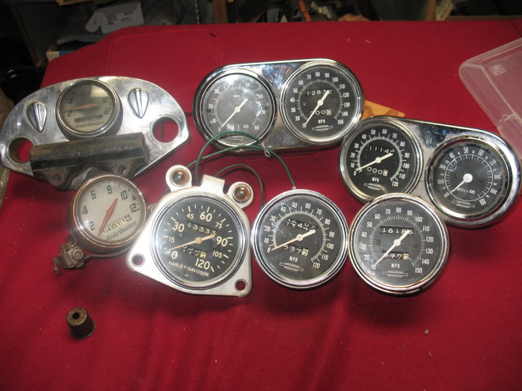 | 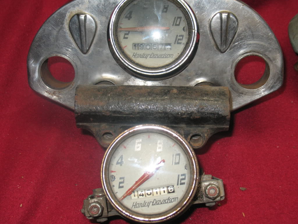 | 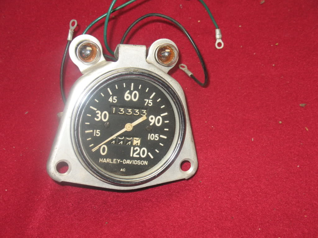 |
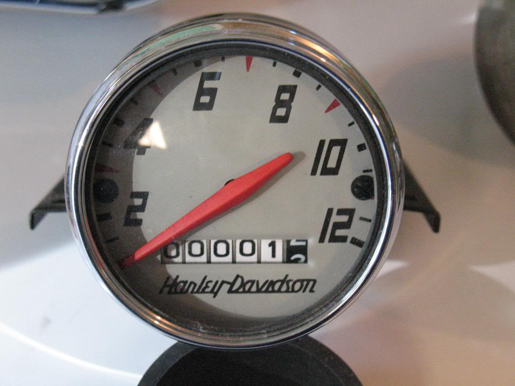
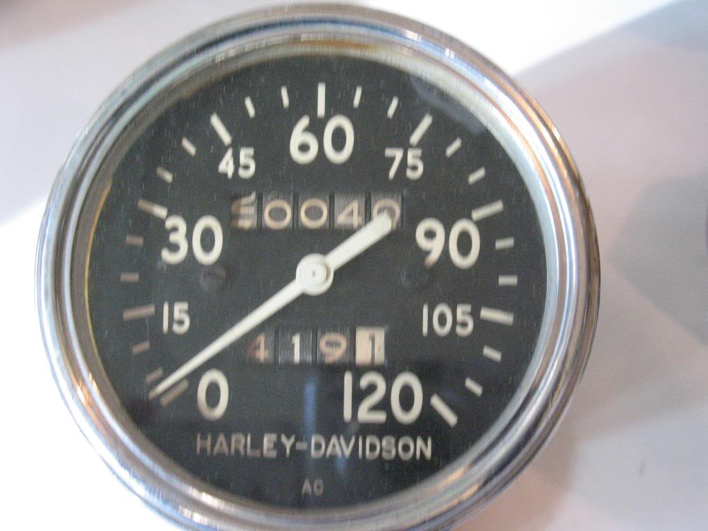
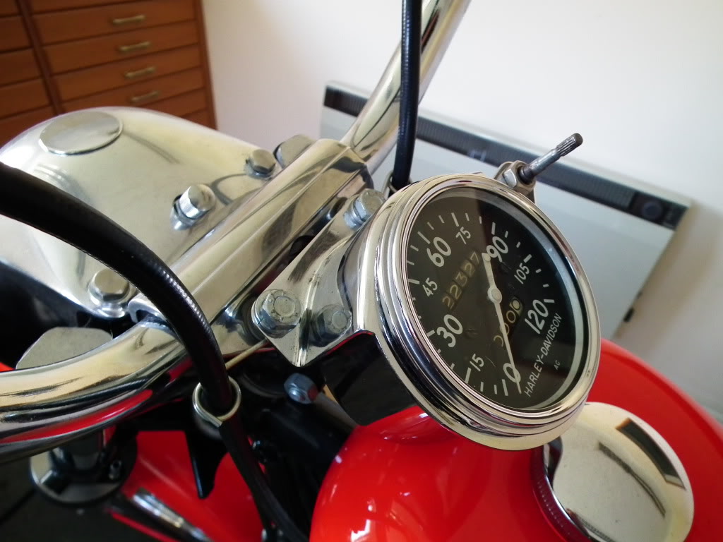
| Sportster gauges from 1957-1969 3) | Here is the speedometer (67007-54A) used on 1955-1956 KH and 1957 and 1958 Sportsters (except C and H models). The “flippers” hide key switches for the ignition and lights. 4) | This A-C speedometer (67007-59), manufactured by United Motors 5), was used from 1959 to 1964 on both the XLH and XLCH models. The bracket shown here is for the XLH; it fits under the locomotive nacelle and the trip odometer cable and knob comes through the nacelle back panel. The XLCH models had a different bracket with the odometer reset cable knob mounting next to the speedo face. 6) |
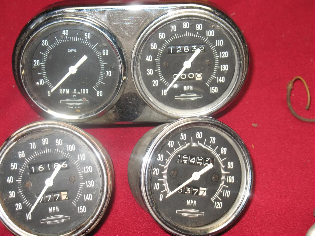 | 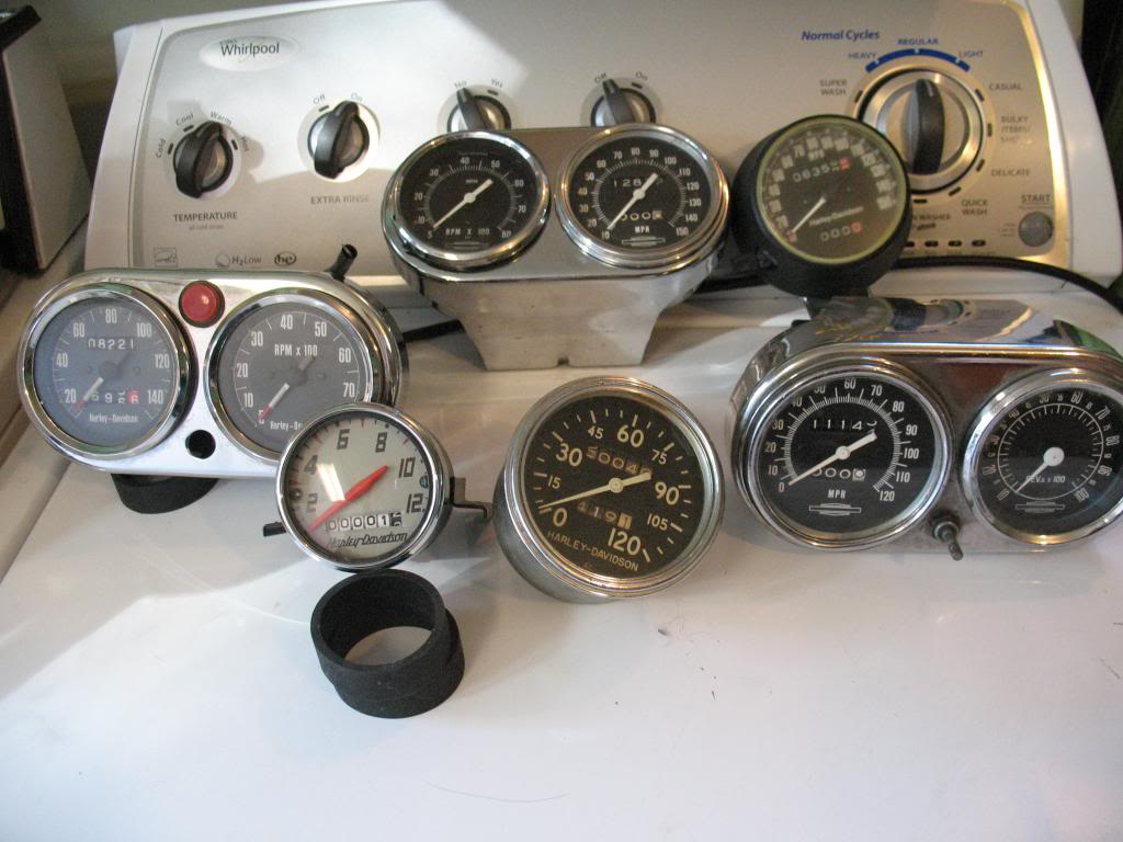 |  |
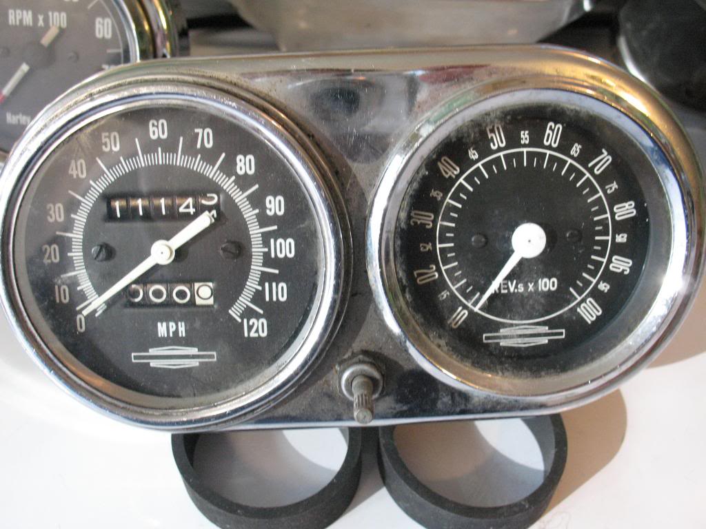
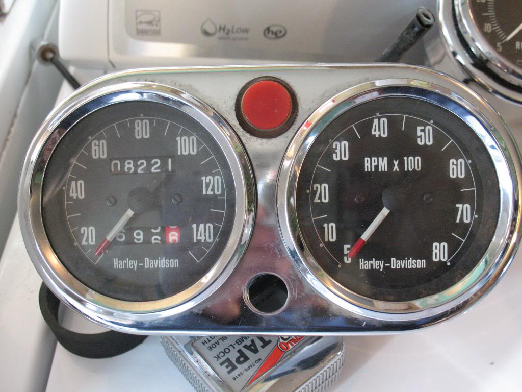
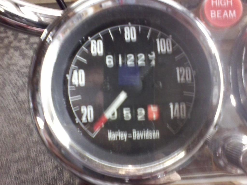
| The so-called Smiths gauges were introduced with the 1965 models. Although the tach was, in fact, built by Smiths, the speedo was still made by AC and is identical to the earlier Speedometer except for the fact. The 120 MPH version (lower right) was used from 1965 to 1967. The 150 MPH version was introduced in 1968 in celebration of a factory tuned Sportster going 150 mph on the Bonneville salt flats. 7) | Here are all of them until at least 1978. 8) | Sportster 1957-1958 (67007-54A) used on 1955-1956 KH and 1957 and 1958 Sportsters (except C and H models)9) 10) |

Speedometer Drive Gear
 |  |  |
| '68 XLCH speedometer drive gear location in the case 17) | Inside view of a 69 XLH speedo drive gear as mounted 18) | |
Staring down a problem with the speedometer not working can be catastrophic when visualizing the possible causes and particularly the effects thereof.
| This.. | Yields that….This particular incident luckily didn't hurt any engine parts | |
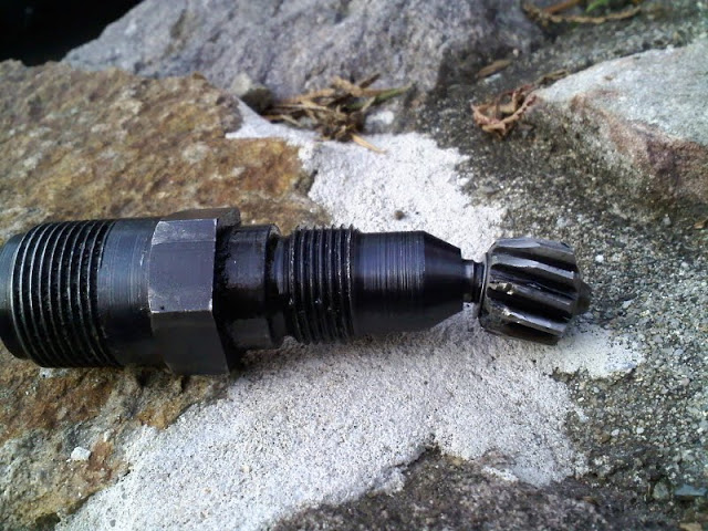 | 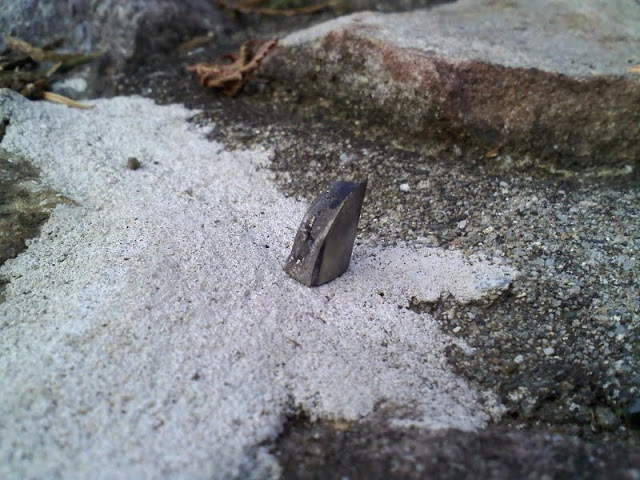 | 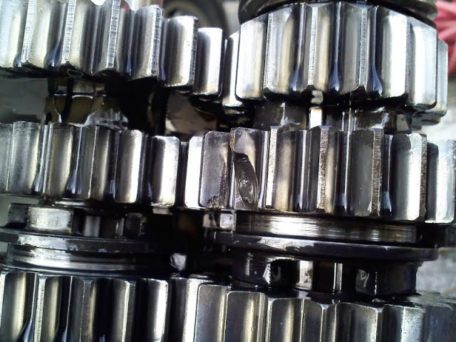 |
| Broken teeth on bent speedo drive unit 19) | Metal pieces in case behind trap door 20) | Busted teeth on tranny 21) |
LIGHTS
Headlight
In Late 1977, Shorter Headlight Bracket Mounting Bolts Used
- In late 1977, shorter bolts were used to mount the headlight bracket to allow it to be installed or removed with the handlebars clamped in place. The shorter bolt also allows for the mounting of the headlight bracket after mounting the speedometer / tachometer bracket underneath the handlebar upper clamp which provides easy access to the wiring connections at the headlight terminal block.
- The shorter bolts 5/16“x18 1-1/8” (43868-72) replaced the longer 5/16“x18 1-1/4” bolts (2871W). The longer bolts can also be shortened for this application. 22)
Brake Light Switch
Front Brake Switch
- All motorcycles shipped after Jan 1, 1969 are equipped with a stoplight switch on the front brake control lever to conform with Federal Motor Vehicle Safety standards. 23)
| 71900-70 with terminal 24) | Late 1969-1972 XLH / XLCH | The handlever bracket has a threaded hole for the plunger type switch which closes the brake light circuit when the lever is moved with one wire leaving connected at the ignition 'hot' and the other at the rear brake light terminal. 25) |
| 72024-71P 26) | 1973 XLH/XLCH | |
| 72001-69 27) | 1974-1978 XLH / XLCH replacement for 1973 XLH/XLCH | |
| 72001-69B 28) | 1979-1981 XLH / XLCH / XLS / XLX replaced 72001-69 for 1973-1978 XLH / XLCH | |
| 71574-82 29) | 1982-1985 XL / XLS / XLX |
Rear Brake Switch
- The MoCo issued a Service Bulletin on November, 28 1969 stating that the 1970 type Sportster rear brake light switch was now being supplied with mounting hardware as a kit, with wiring, (72004-67) for replacement of earlier switches used back to 1967.
- The new switch was mounted on the (rear fork) right side and activated by an adjustable bracket on the brake operating rod.
- The switch is also recommended for replacement on Late 1969 models (mounted at the rear chain guard). In some cases, the L69 switches strike the saddlebag when the rear fork bottoms out. The new switch solves that problem. 30)
| 72004-52 complete 31) 32) | 1952-1958 K/KH Models 1957-1958 XL 1959-1966 XLH/XLCH |
| 72005-67 kit with wiring 33) | 1967 XLH/XLCH |
| 72004-67 kit with wiring 34) | Replacement for 1967-1969 XLH/XLCH |
| 72005-67A kit with wiring 35) 36) 37) | 1968-1971 XLH/XLCH retro-fit replacement for 1967-1972 XLH/XLCH 38) |
| 72004-70 switch only 39) 40) | 1973-1974 XLH/XLCH |
| 72004-75 switch only 41) | 1975-1976 XLH/XLCH |
| 72001-69B 42) | 1977-1978 XLH / XLCH |
| 72023-51A 43) | 1979-1985 XL/XLCH/XLS/XLX |
Handlebar Braking Switch
Brake Pedal Braking Switch
Taillight - License Light
Turn Signals
(1973-85 Simple Turn Signal Function)
These model years HD implemented a basic turn signal circuit using a bi-metallic, current/heat-controlled, Turn Signal Flasher Unit similar to those in automobiles. The 12v power wire feeds thru the Flasher and then goes to the handlebar switches. The Left or Right handlebar turn signal switch could be pressed to feed the power to the bulbs on that side of the bike. When connected to the bulbs, thus completing the circuit, the Flasher unit would supply power until the current flowing through it would heat the bi-metallic elements sufficiently to cause a break (like a circuit breaker) in the circuit. Once the flasher cooled down, the bi-metallic elements would again conduct power to the turn signal bulbs, thus causing an on-off cycle that repeated until the handlebar switch was released.
From 1973-1981, the handlebar TS switches were small pushbuttons. They were momentary contact. The turn signal only stayed flashing while the button was depressed.
From 1982-1985, the handlebar TS housings were changed, creating a larger TS button. The switches were still momentary contact, working only while the button was depressed.
- (Converting to LEDs) - Because of the way these bikes were wired, you can replace the single current/heat-activated flasher with a new electronic flasher that is capable of properly flashing LEDs or Incandescent bulbs. However, the indicator light may need to be modified by grounding one side and feeding power from the right and left circuits thru diodes to the power side of the indicator.
Signal-STAT Flashers
From a bulletin in 1961:
Different flasher modules have different characteristics. It is important to use the appropriate one when replacing them. For instance:
- Flasher (68543-61) was originally used for directional signals with 21 candlepower to the front and rear lamps (6872-50) and 1 candlepower pilot lamps (71090-47). If any of the signal bulbs burn out, the pilot lamp in the same circuit will remain on.44) Flasher (68543-61A) was the replacement for directional signals. 45)
- Flasher (68542-61) is used for pursuit lamps or other flashing lamps which use either one or two 32 candlepower lamps (68715-49).46)
| Year model | Part # | Used For | Markings | Application Voltage | Notes |
| 1957-E1963 | 68543-61 | Directional signals | N 221-6V | 6 | 3-prongs: X (hot), L (switched), P (not used) |
| 1957-1965 | 68543-61A | Directional signals | 143-12V | 6 | Replaced 68543-61 in L1963. Disregard the 12V markings per HD. 2 prongs: X (hot), L (switched) |
| 68542-61 | Pursuit lamps | F 421-6V | 6 |
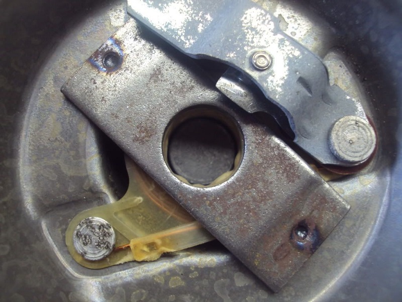
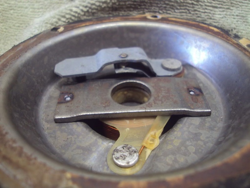
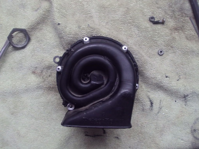
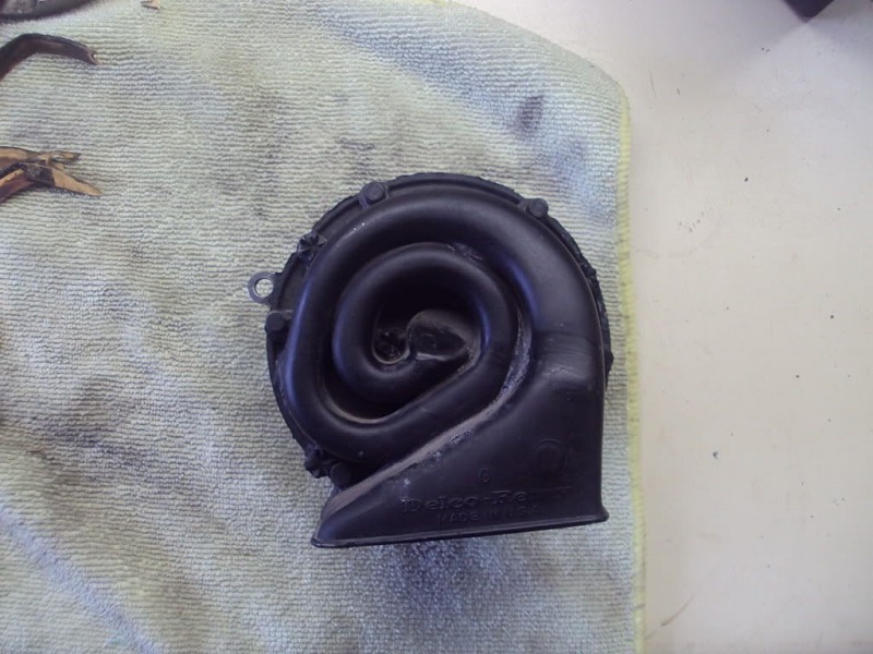
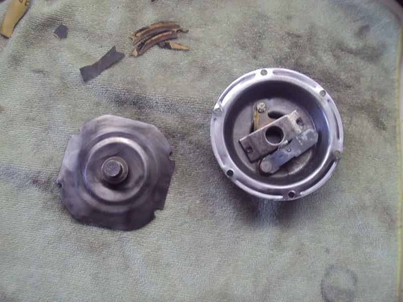
Horn
This is a rebuild of the stock Delco Remy horn from a 68 XLCH.
There are horn rebuild kits available, but they are pretty simple in design and a good cleaning may be all that is needed.
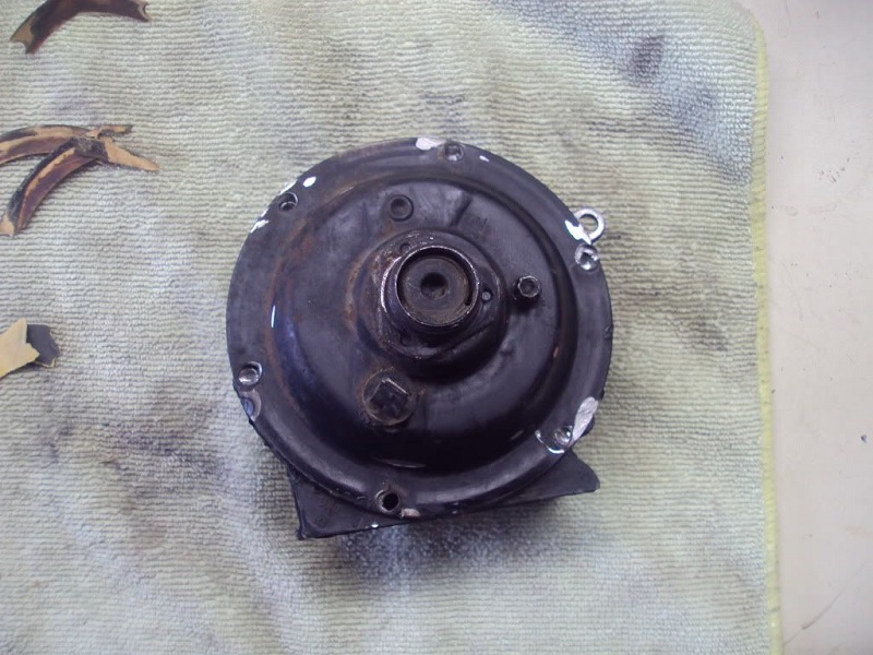
A bench grinder was used to grind the rivet faces off flat. You can also use a drill bit that is larger than the hole in the rivets to drill off the face.
Then you can use a center punch to knock the rivets out or pull them out of the other side with pliers.
Then separate the halves and clean up all surfaces with sand paper or a wire wheel.
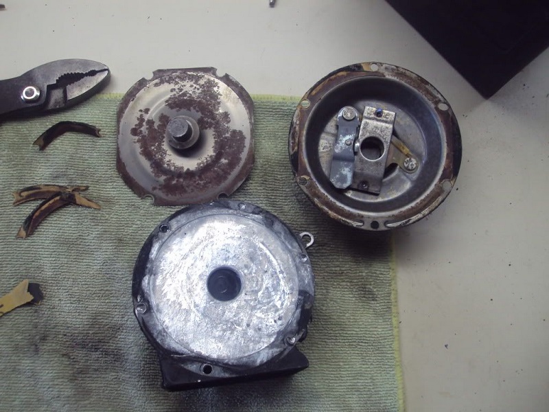
You can check the continuity of the coil but be careful not to break the wire.
Use some 400 grit sand paper to lightly resurface the contact points (you may have to push the lower contact down to get the sandpaper in and out).
After everything is cleaned up, reassemble the horn and test.
There is a small screw on the back of the horn, you can make slight turns on it to adjust the horn for the best sound.
Keep in mind that too far one way or the other and the horn will not work at all. Use pop rivets to put the horn back together after a thin coat of RTV.
Ensure that you don't get any sealant on the vibrating plate or it will not work.