Table of Contents

IH: Suspension - Sub-03D
1957-1978 Swingarm
Swingarm Assembly
Parts Orientation and Installation
Bearings
1957-E1974 bearing part# is (47521-52), 2 required. It's a Timken tapered bearing, now obsoleted by HD.
The bearing can still be bought under the manufacturer numbers: Outer race: (17520), Inner race/bearing (17580).
In February of 1974, the MoCo changed to bearing kit (47550-74) and it was supplied through parts order in place of individual bearing (47521-52).
The kit has 2 Timken tapered bearings (47521-74) which are .100“ narrower than the original production bearings: Outer Race (11520), Bearing (11590).
See also Service Bulletin No. 688 dated May 12, 1975.
Either bearings can be used but All the parts required for each must be used together to obtain the correct rear fork bearing fit.
The small end of the bearing cone is installed from the inner side of each pivot.
| Parts for Either Bearing Setup (don't mix them up) | ||
| 1957-E1974 Bearing 47521-52 | L1974-up Rear Fork Bearing Kit | |
| Pivot Bolt Nut | 47512-52 | 47512-74 |
| Left Bearing Locknut | 47514-52 | 47514-74 |
| Right Bearing Locknut | 47515-52 | 47515-74 |
| Outer Spacer | 47517-52 | 47517-74 |
| Bearing ( 2 used) | 47521-52 | 47521-74 |
Outer Bearing Races
Orientation:
There's been a lot of debate on orientation of the bearing races (wide side facing in or out). 1)
Those in the know have agreed the proper way to assemble the bearings is (wide side in as in the pic below).
That puts you installing the bearing cone/inner race from the inner side of each pivot.
The FSMs do not make this clear and cause confusion. The bearings insert into the inner side pivot bore.
Installation:
The bearing races are not a tight fit in the swing arm when installing them (more of a light interference fit). 2)
It's all about assembly and loading the bearings.
They need to be able to move when you tighten up the nut on the swing arm pivot to set the preload.
The best way to get the bearing races in and out is with a large nut and bolt, like 1/2” UNF, and some large flat washers.
You can use socket wrenches as spacers too.
Put a socket on the bearing race that is just smaller than the outside diameter of the bearing race.
Then put a socket over the hole in the swingarm, where the socket is large enough to allow the bearing race to clear the inside of it.
Run your bolt, or a length of all thread rod through the holes in the middles of the sockets and tighten the nut(s).
The race should slide right in or out.
Click on a pic to enlarge:
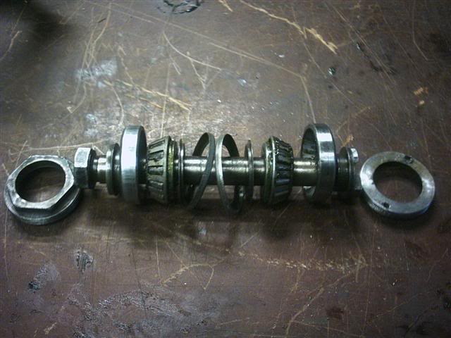 |
| 1980 Swingarm bolt assembly 3) |
Guide to Swingarm Bearing Replacement
Article and Pics by ericfreeman of the XLFORUM 4)
Click on a pic to enlarge:
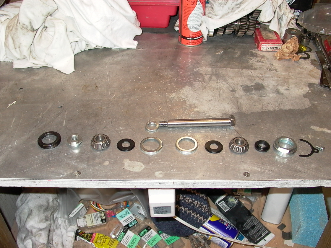
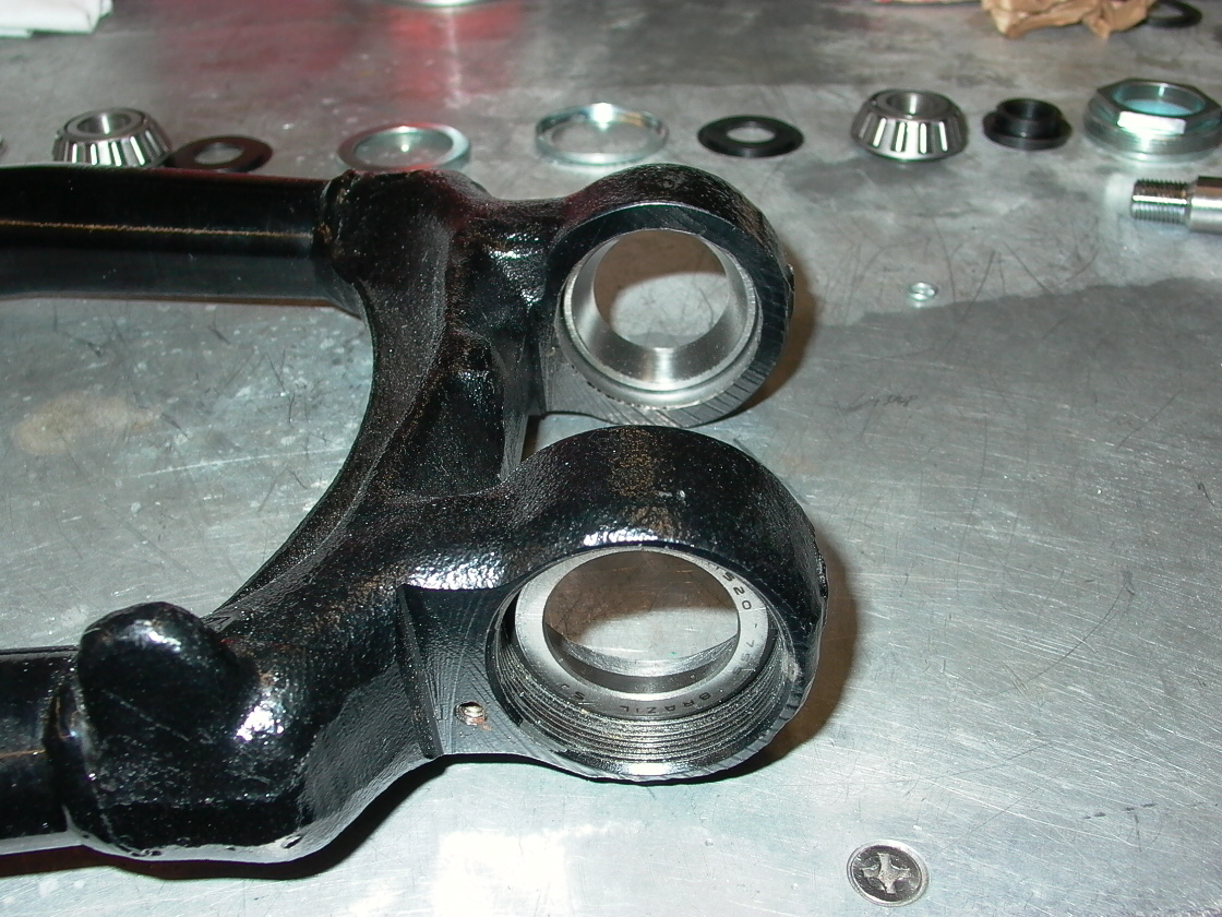
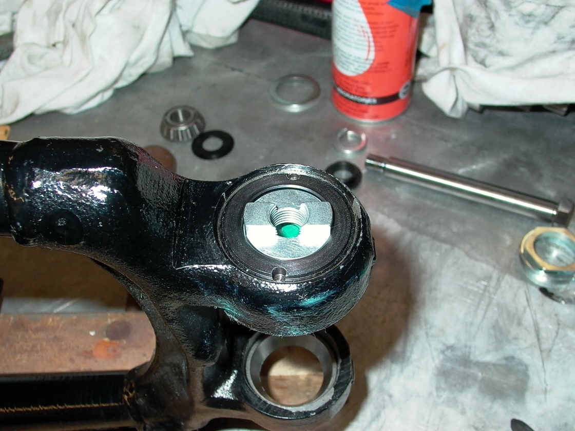
| Here are all the parts laid out as they will fit into the swingarm 5) → | The bearing outer races are already installed in the swingarm 6) | Inspect the swingarm inner surfaces to ensure they are clean. You can see the bearing outer race already installed in the other side. 7) |
 |  | 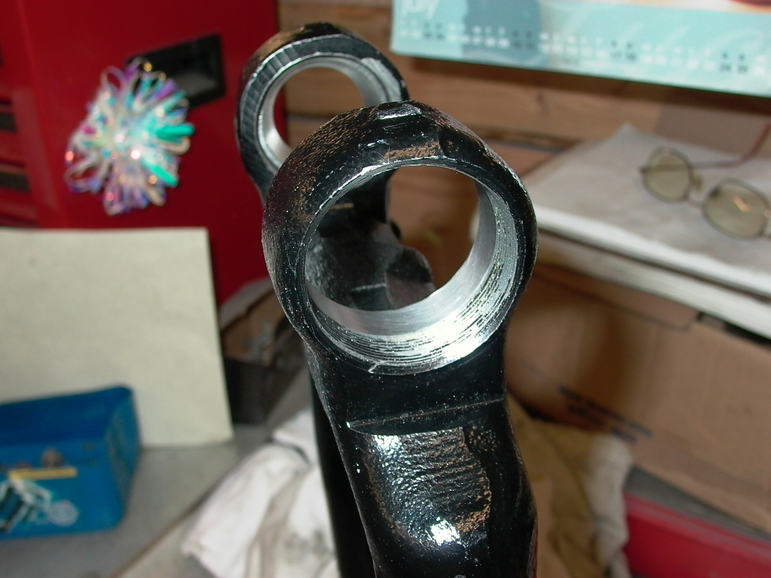 |
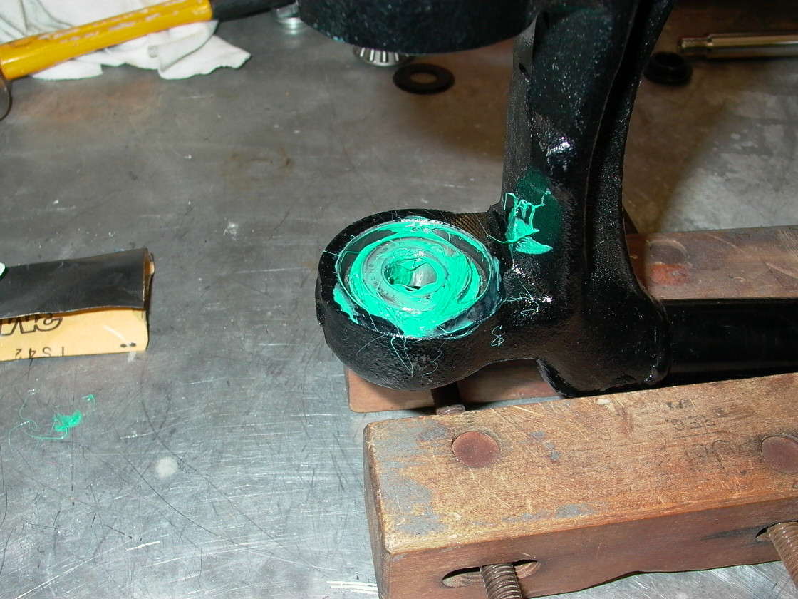
| Use some 800 wet/dry sandpaper to smooth the surface 8)→ | Press the outer races into place using an appropriate tool.9) | Grease the tapered roller bearing. I used a very sticky marine grease that won't wash out. It's not for bearings that rotate at high speed like wheel bearings but will be fine for the swingarm that just oscillates through a small arc. 10) |
 |  |  |
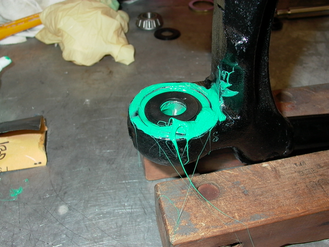
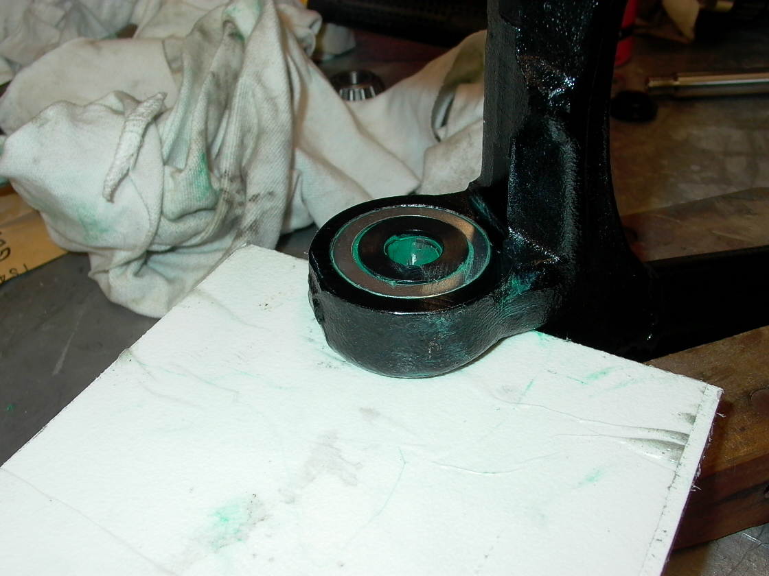
| Install the bearing in the outer race11)→ | Pack the area around the bearing with more grease and fit the spacer on the bearing, with the smaller diameter section facing up so it will fit into the hole in the dust cover.12) | Install the dust seal, ensuring it fits flush with the swingarm boss. The flat side of the spacer should protrude a little through the dust seal hole. This spacer will seat against the frame when the bearing preload is set.13) |
 |  |  |
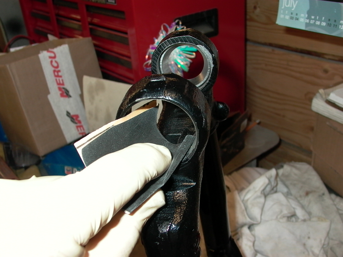
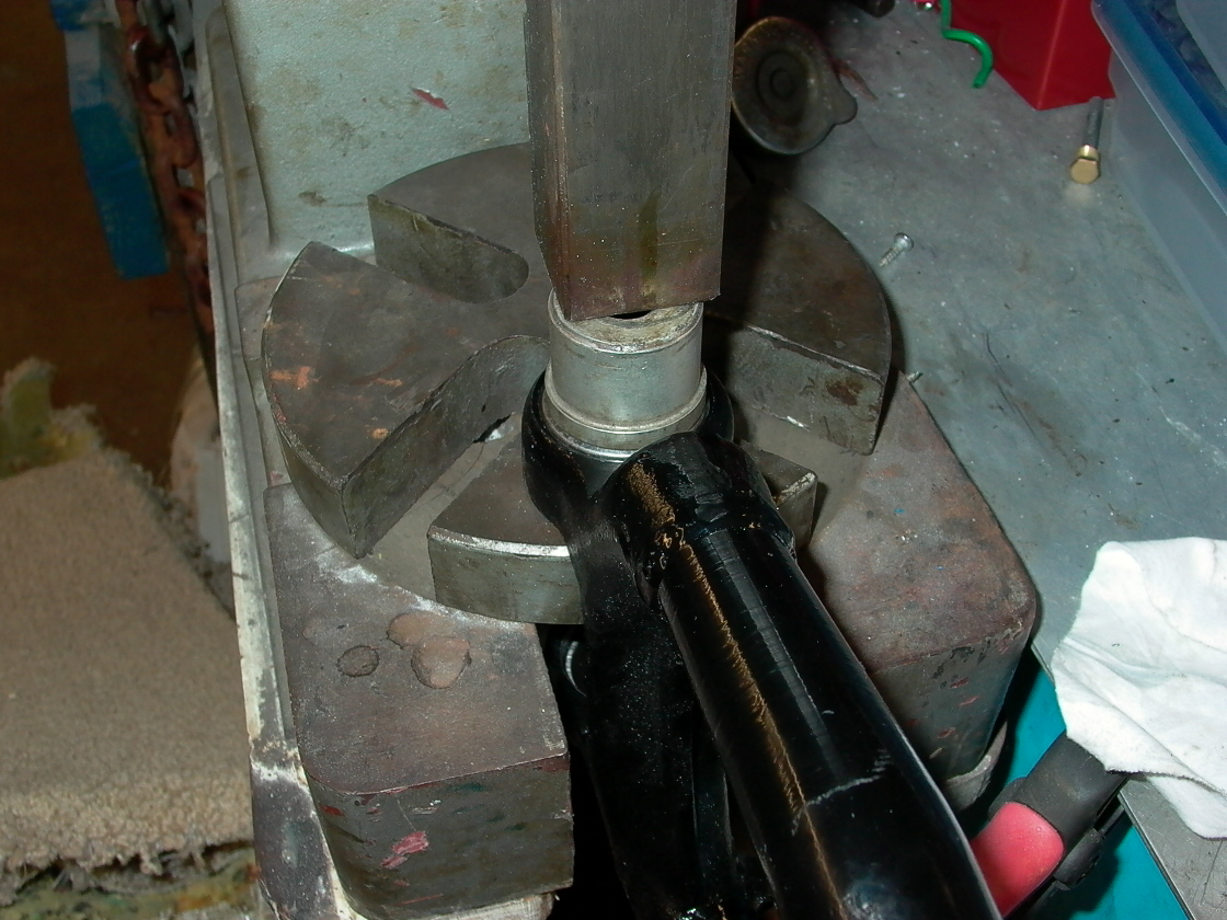
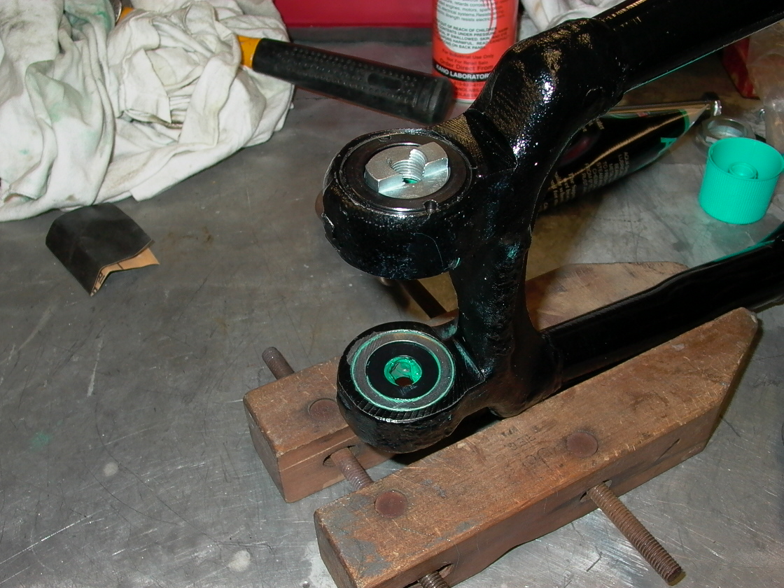
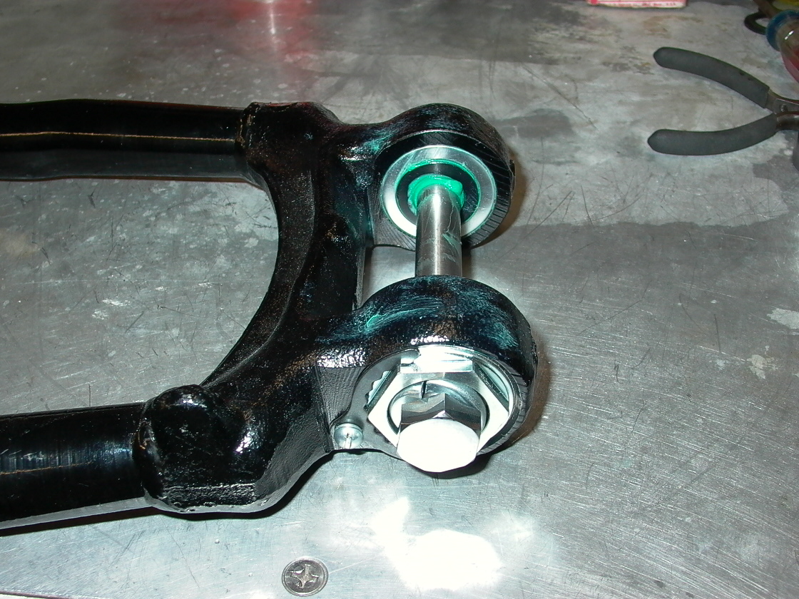
| Here's the outer view of the leftside assembly, with the pivot bolt nut and bearing locknut in place. I'll wait to lock the bearing locknut into place until I trial-fit the swingarm to ensure I can properly adjust the left bearing preload.14)→ | Repeat the procedure on the other side. Here's what it looks like with both bearings installed.15) | This is the entire setup assembled to keep all the parts together prior to fitting the swingarm in the frame.16) |
 |  |  |
Swingarm Installation
- For the swing arm its pretty easy when you know how it works. The pivot bolt when tightened presses the inner bearing and race,bearing spacer, and dust shield onto both sides of the frame and the actual adjustment is done by tightening bearing locknut on the right side till you have the desired preload once the preload is set then comes the lock-ring so the right bearing locknut cant turn. 17)
- When you install the locknut do not stake it as advised in the FSM. A little [not a lot] of blue locktite is all that it needs, and whoever needs to remove it one day will be thankful. 18)
- Factory recommendation from bulletin in 1972: 19)
- Reinstall rear fork (be sure the left side nut registers in the crankcase slot). Weigh with spring scale before tightening the right side bearing race nut.
- Tighten nut until you get 1-2 pounds of bearing preload. Install the bearing nut lock and screw.
Bearing Preload
Comments from piniongear
After tightening the pivot bolt you should be able to obtain resistance by tightening the right side bearing lock nut.
Using a scale, tighten the lock nut to where it has 4-5 lbs resistance. 20)
Comments from Dr Dick 21)
Why preload? It makes sure the bearings aren't loose. How much preload? Too little makes your bike “flighty”. It wont “suretrack”. I call it “marshmellow-ish”. Too much and you will burn thru bearings at an alarming rate. Where does the preload come from? Swingarm front casting flex.
Frame: A close look will show that both bearing inners and everything that slides over or attaches to the pivot bolt becomes solidified as one with the frame when the pivot bolt is tightened. They are immobile.
Swingarm: The 1-3/8“ hex adjuster forces the bearing outers into contact with the solidly located inners. This is possible because the outers aren't a tight press into the arm casting bores. Turning the 1-3/8” moves the outers closer to or farther from the non moving inners. These outers are part of the arm, not the frame.
So when the 1-3/8“ is loose, the arm is sloppy. You tighten the adjuster until all play just disappears. Now the outers have contacted the inners. The arm is not loose but it has no drag either.
If you hook a fish scale to the far end of the arm, it will weigh about 4lbs. If you raise the scale (and the arm) reading stays constant at 4lbs. Same happens as you lower scale. The reading stays at 4 lbs. Now you crank up 1/4 turn on the adjuster. What does this do? “well, that's a no brainer dick. it jams the bearing tighter”. Yes, but the bearings are very hard and they won't distort much from the pressure. Instead the arm front casting flexes open under the pressure. What ever the pressure applied to crunch the bearings, the same is forcing the casting flex open.
Now you put the scale on the arm. The scale won't get a solid reading of at-rest weight. If you raise the scale you now get 4-1/2 lbs and 3-1/2 as you lower. That's one half pound of drag. That drag is from the internal friction of the bearing, as it is under a 'pre'-load. Now you crank up another 1/8 turn on the adjuster. You now get 1 lb of drag (5 on upswing, 3 on drop, so far so good). You crank up the adjuster more looking for your two lbs. Funny thing happens. The drag isn't increasing as much. On 74-up bearings, you may not even get 2 lbs unless you tighten the Hell out of the adjuster? This is especially true for 78< arms. What's up with that?
You know what? The bearing is acting just as it should. It's carrying a larger load with out creating more friction. Isn't that what bearings are supposed to do? What I found out: The FSM says 1-2 lbs drag. But everyone just defaults to 2 lbs. At two lbs, the bearing life is dismal. At 1 lb, the bearings will last at least 3x longer. Does a tight preload control the arm better? Yes, at first. But it degrades as soon as the bearings get worn. And at 2 lbs, the bearings will wear to a point that is much worse than an unworn 1 lb'er rather quickly.
On any arm, the 73< bearing setup will control the arm better for any given preload and will outlast the 74> twice over.