Table of Contents
This is an old revision of the document!

REF: Carburetor
CARBURETOR - Technical Info
This listing of carbs will be condensed to just carb numbers at a later date. It has already been filtered into the appropriate areas in the main technical menu.
FACTORY CARBURETORS
Linkert Model M and DC Carbs (1965 and Earlier)
- Three different carburator families were used on the K and Sportsters through 1969. Three models of the venerable Linkert Model M carbs were used on K and KH. Sportsters used various incarnations of the Linkert DC and M carbs from 1957 through 1965. 1)
The Linkert Model M
- The model M carburetor is a plain tube carb containing a venturi and a discharge nozzle through which fuel is drawn into the air stream passing through the venture. The quantity of fuel is metered by two jets or openings (one for low speed and the other for high speed) before entering the nozzle.
- Needle valves in the low and high speed passages allow the carburetor to be adjusted for the slightly varying and individual needs of the engine. Once the carb is adjusted, it requires little if any attention. At most, adjustments might be a few clicks or notches richer or leaner on the needles are all that should be needed to correct air/ fuel mixture for changes in weather condition. All final adjustments should be made at full operating temps. 2)
- Features:
- High and low speed needles
- Low speed needle lift lever
- Throttle lever
- Throttle lever lock screw
- Throttle stop
- Bowl vent
- Choke lever and disc
- 1-5/16“ Venturi (27363-41) for 1954-1956 KH models3)
- (27146-52) M53 (1952) for all Harley K models4)
- (27146-52A) M53A1 (1952-1956) for all Harley K models replaced the M53 with: 5)
- Most K models ran a Linkert M model Carb up until around 1965.
The Linkert Model DC
- The model DC is a plain tube carburetor. It's main air/ fuel mixture passage consists of a venturi section and discharge nozzle. A fixed jet and adjustable high speed needle valve, of limited, meter the high speed fuel supply as it is fed into the venturi section of the throttle barrel. The low speed needle valve meters the low speed fuel/ air mixture as it is fed into the throttle barrel near the throttle disc. There are no moving parts except the throttle shaft, disc and the bowl float mechanism. 9)
- The Linkert DC found on the 1959-1965 Harley Servi-car 45 flathead was left-handed, the float was on the right side of the ones put on Sportsters and Big-twins, since Harley flatheads have the carburetor on the left side of the engine. Other than the Harley Shovelhead carb and the DC-2 on the Servi-car, all Linkert DC versions have the same carb body with the same size venture, with a one-piece casting and the difference was changing the jet size, and modifying the inlet valve. 10), found primarily on '50s and '60s Harley-Davidson Sportsters.
- Being simple in design:
- Choke lever assembly for 1957 models only
- Throttle lever stop
- Main nozzle float valve and seat
- Idle tube assembly
- Float bowl mounted on right side
- Venturi
- Discharge nozzle
- Adjustable high and low speed nozzles, and a fixed jet.
| Carb Model | HD Bike Used On | Idle Bleed | Idle Tube Feed | Fixed Jet | Throttle Disc | Turns (high speed setting) | Turns (idle speed setting) |
|---|---|---|---|---|---|---|---|
| (27155-57) was the first Sportster carburetor then replaced with (27155-57A) both introduced for 1957-1959 Sportsters 11) | |||||||
| DC-1 | 1957-1958 Sportster XL Early Style 12) | #53 .0595 | #69 .0293 | #9 .067 | 9A 13) | 3/4” to 1-1/4“ | 3/4” to 1“ 14) |
| DC-1L | 1959-1960 Sportster XL 15) | #53 .0595 | #69 .0293 | #4 .0625 | 9A 16) | 3/4” to 1-1/4“ | 1” to 1-1/4“ 17) |
| DC-1M | 1959-1960 Sportster XL 18) | #53 .0595 | #69 .0293 | #1 .052 | 9A 19) | 3/4” to 1-1/4“ | 1” 20) |
| DC-2 | 1959-65 Servicar (smaller venturi, opposite float bowl)21) | #51 .067 | #70 .028 | #20 .0452 | 12 22) | 3/4“ to 1-1/4” | 1“ to 1-1/4” 23) |
| DC-6 | 1961 Sportster XLH and XLCH 24) | #53 .0595 | #69 .0293 | #4 .0625 | 9A 25) | ||
| DC-7 | 1966 Big-Twin FL and FLH (larger venturi) 26) | #53 .0595 | #69 .0293 | .070 | 9A 27) | ||
| DC-10 | 1962 and mid-63 Sportster XLH and XLCH 28) | #53 .0595 | #69 .0293 | #4 .0625 | 9A 29) | 3/4“ to 1-1/4” | 1“ to 1-1/4” 30) |
| DC-12 | 1966 Big-Twin FL and FLH mid-1963 1964 1965 Sportster XLH and XLCH 31) | #53 .0595 | #69 .0293 | #4 .0625 | 9A 32) | ||
Adjusting the Linkert DC
| Carb Idle Speed |
|---|
| Adjust until engine idles and runs smoothly |
- A properly adjusted carburetor requires little re-adjustment according to the FSM. It shouldn't be necessary to change the adjuster of the low speed needle more than 1/8 turn or the high speed adjuster more than 1/4 turn richer or leaner to obtain correct mixture for a change in altitude unless there are some worn or obstructed parts to consider.33)
- Before attempting to correct faulty engine performance through carb adjustment, eliminate all other possible causes for poor engine performance such as bad spark plugs, poor timing, mal-adjusted tappets, dirty air cleaner, leaking gaskets and poor manifold connections.34)
- The fuel/ air mixture for low engine speed is regulated by the low speed needle only. The fuel supply for high speed is regulated by a combination of the adjustable needle and the fixed jet (which dominates the regulation of high speed fuel supply). The high speed needle provides a supplement, to a degree, of the fuel supplied by the fixed jet when it is found that slightly enrichening the mixture improves engine performance. 35)
- The FSM may be of little use from this point on.
- Its trial and error now to find out what works for you. Idle speed is critical in easy starting. Low idle can make bikes difficult to start and too high is uncomfortable at stops. There is a sweet spot in there somewhere that you must find. 1200 rpm is a good speed to begin your fine tuning. 42)
- When it's warm and it's been off for a minute. I only need to push the kicker through and it starts up. If it's been off for a bit, the first kick without retarding the mag results in a locked up kicker, feeling there is a fuel charge sitting in the combustion chamber. The idle adjustment screw can be backed out as far as I want and it doesn't change much at all. If I go too lean, it will stumble of course. If the idle adj. screw is 1/8th out from stumble as the manual suggests, I have a hard time with starting. 43)
- The bigger picture regarding these adjustments for this the throttle plate must be: Positioned (milled notch up & facing air cleaner) and registered (even peripheral contact to throttle body at fully closed) correctly.44)
- Removing the brass screw plug near idle mix screw exposes the idle well. On the side wall of the well you will see a hole that feeds mixture (note that I didn't say fuel) to the idle mix screw. Mixture that enters this hole is regulated by the adjuster screw, and discharged into air stream thru a hole drilled close to intake manifold. This supplies most of the idle mixture.45)
- Then on floor of the well you will see a series of 4 tiny holes. These are the transition holes. The remainder of idle mixture comes from the 1st (one closest to manifold) transition hole as its open to low manifold pressure. The other 3 are open to the higher atmospheric pressure because they are on the other side of throttle plate at idle. That means lots of air enters the well thru the 3 hi pressure holes. All that air dilutes the fuel into a 'mixture'. Because the idle mix screw adjusts the flow of this mixture a funny thing happens as you richen it. Because the air component is so much less dense than the fuel component the mix screw is less a restriction to the air than to the fuel- its gets to a point where opening it adds more air then it does fuel. In other words it will only get so rich no matter how far you back it out. This is a DC Linkert anomaly because 4 holes spread over a very large throttle plate swing bleed a lot of air into the well on idle. Things change as soon as you begin opening throttle plate. Now the number of transition holes open to low pressure is larger and the number open to atmospheric pressure is less. ie: the air component of the mixture drops. Now the idle mix screw is controlling a more fuel laden mixture. The ratio of air to fuel continuously drops as you open the throttle until the last holes is on downstream of the plate. The mix screw will have a larger effect on low throttle running than idling. You need to set screw where you get good around town manners and then adjust the speed screw to the appropriate speed.46)
- This is a delicate balancing act that will change as the properties of the air change: temperature, pressure (altitude or barometer), and water content (humidity). The dc is prone to this fickleness due to the large air bleed variation at different throttle plate positions.47)
- The S&S carbs based on the DC Linkert used only two transition holes in the early years and three later on. Both show a marked improvement in weather stability.48)
- These carbs are extremely touchy to float level at just off idle throttle positions. Problems show as spitting / coughing on one end of the spectrum to burbiling / stumbling at the other end. Many owners will report how precise you need to be with float levels to get your bike to run as a fine watch.These guys also eventually learn two things:49)
- Float levels will rise on their own due to the steel inlet needle wearing the brass seat away. This is a mileage thing– just like tire and chain wear (steel needle carbs only- linkert, orig earlies and orignal L's). 50)
- Secondly and more importantly, these carbs are very susceptible to errant low speed metering as fuel composition, barometric pressure, humidity, and air temperature vary. Trying to hit the sweet spot requires many float adjustments, idle mixture settings, idle speed settings and road tests. To do away with that wasted time and aggravation, I fit all my side bowl carbs with an externally adjustable float level. Now I can change float level on a whim.51)
Linkert DC Rebuilding
- A gasket kit (which includes the bowl and body gaskets, seals, and an o-ring for the bowl vent tube instead of a gasket) and some carburetor cleaner is all you need to rebuild a Linkert DC carb. No special tools are required. All DC carbs use the same gaskets and seals. If needed, a larger gasket set is available, and includes the gaskets and seals, plus an assortment of small springs and screws. 52)
| Carb Assembly is HD Part Number: 27155-57B53) | |||
| Model (marked on carb) | Idle Port Hole Drill Sizes | Model (marked on carb) | High Speed Hole Drill Sizes |
|---|---|---|---|
| DC-1, 1L, 1M, 10 DC-2 | #70 (0.028 in) #56 (0.0465 in) | DC-1, 1L, 1M, 10, 6, 7, 12 DC-2 | #55 (0.052 in) #70 (0.028 in) |
Tillotson HD Carb (1966-1971)
- The model HD is a dual-venture, diaphragm-type carburetor with an automatic economizer and accelerating pump. The fuel inlet needle is operated by a compression spring balanced lever that is controlled by the diaphragm to regulate fuel flow into the metering chamber. The amount of fuel flowing into the carb metering chamber is exactly equal to amount of fuel demand of the engine. 56)
- This type of fuel control operates at any tilt angle and is resistant to any vibration which could cause a poor fuel/ air mixture or flooding.57)
- The small primary venture is offset to the bottom of the large secondary venture where the main nozzle outlet protrudes from the metering chamber. The accel. pump discharges into the small venture to take advantage of the venture pressure drop that breaks up the solid stream of accelerating-pump fuel.58)
- The accelerating unit is a positive-acting plunger type pump connected to the throttle shaft through a cam lever. The pump plunger is a spring loaded leather cup that operates in a smooth plastic cylinder drawing fuel directly from the metering chamber to provide extra fuel for acceleration.59)
- The automatic economizer is a hydraulically operated enrichment valve controlling the main nozzle fuel mixture at very low engine speed. The valve opens an auxiliary fixed main jet as the venture air flow decreases, allowing the fuel mixture to be maintained at a full power richness. As the air flow through the carb increases, or as engine speed increases, the valve closes to prevent an over-rich mixture at intermediate speeds. 60)
- Choke/ Initial Startup: The choke is in the closed position. As the engine is cranked, the entire metering system (idle, intermediate and nozzle) is subjected to engine suction which is transmitted to the fuel chamber, via the metering channels, creating a low pressure on the fuel side of the metering diaphragm. Atmospheric pressure from the vent moves the metering diaphragm toward the inlet control lever to allow fuel to enter carb thru the needle and seat. Fuel is then forced thru the metering system out into the carburetor mixing passage and into the manifold and engine. When the engine fires up, the volume of air drawn thru the carb increases, and the spring loaded top half of the choke shutter opens to provide the additional air required by the engine, to prevent an over-rich mixture. The choke can then be moved to a half-open position for engine warm-up. During hot weather or after the engine has been run long enough to reach stable operating temperature, and then shut off for a short period of time, a small amount of fuel vapor may form in the fuel lines or in the fuel chamber of the carb. The vapor in the fuel lines will enter the fuel inlet and rise out of the fuel outlet, to be vented back into the fuel tank. The vapor that forms in the fuel chamber must escape through the metering system because there is no other vent to the fuel chamber. Starting a warm engine is most easily accomplished by placing the choke in the half closed position and starting as described. The choke helps to quickly remove the vapor out of the fuel system so that the fuel flowing through the carb and fuel line can cool the system to a normal temperature. Starting is usually easier using the choke (full choke for cold engine, half choke for warm engine). 61)
- Idle Operation: The throttle shutter is slightly open when the engine is idling and the carb mixing passage on the engine side of the throttle shutter is exposed to engine suction, while the mixing passage between the throttle shutter and the air cleaner is at nearly atmospheric pressure. Engine suction (transmitted through the primary idle discharge port to the fuel chamber side of the metering diaphragm via the bypass chamber, idle fuel supply channel, intermediate adjustment channel, nozzle well, main fuel jet and main fuel supply channel) creates a sub atmospheric pressure in the fuel chamber. The metering diaphragm is forced upward by atmospheric pressure, moving the inlet control lever to overcome the inlet compression spring pressure, allowing fuel to enter the fuel chamber through the inlet needle and seat. Fuel flows through the main supply, main fuel jet, nozzle well, intermediate adjustment channel (where it mixes with air from the idle air-bleed) idle fuel supply channel, to the bypass chamber, where it mixes with air from the secondary idle discharge ports, and on out into the carb mixing passage through the primary idle discharge port. The mixture of well atomized fuel and air then travels through the manifold and into the engine combustion chamber. 62)
- Acceleration: Acceleration is accomplished by the use of a positive-acting accelerator pump, actuated by a cam lever from the throttle. The pump cylinder is filled when the pump is raised to the top of it's stroke. Fuel is drawn from the fuel chamber, through the accelerating pump inlet channel, past the inlet check valve. The outlet check valve is closed to prevent air from being drawn in to the accelerating pump system. As the accelerating pump is depressed, the pressure of the fuel closes the inlet check valve, the fuel flows through the pump channels, past the outlet check valve, through the accelerating pump outlet channel and through the boost venture into the carburetor mixing passage. 63)
- Intermediate or Cruise Operation: Fuel is delivered into the carb and as the throttle shutter opens to increase engine speed, the secondary idle discharge ports are exposed to engine suction and fuel is delivered from both the primary and secondary idle discharge ports to supply the additional fuel demand by the engine. As the throttle shutter is opened farther, the air velocity through the boost venture increases, creating a low pressure area at the nozzle outlet. Fuel flows from the fuel channel through the nozzle outlet via the nozzle well, main fuel jet, main fuel supply channel, and economizer valve when the pressure at the nozzle outlet is less than the pressure in the fuel chamber. At idle and lower intermediate speeds, the check ball in the economizer valve is away from the seat, allowing free flow from the fuel chamber through the economizer valve to the nozzle well and nozzle outlet. Fuel flow from the primary and secondary idle ports decreases as fuel flow from the nozzle outlet increases. 64)
- High Speed Operation: Fuel flow from the nozzle outlet increases as the shutter is opened past the intermediate position to the fully open position. Fuel is delivered through the nozzle outlet from the fuel chamber via the main fuel supply channel and the main fuel jet. The increased pressure difference between the small venture and the metering chamber, plus the force of fuel flowing through the economizer valve, causes the check ball to seat, stopping the fuel flow from this part of the main metering system. This gives increased economy at high speeds. The diaphragm action and the method of fuel delivery to the fuel chamber is the same as previously described. 65)
- Features: 66)
- Low speed needle
- Intermediate needle
- Throttle lever
- Throttle stop
- Choke lever
- Accelerator pump
- Inlet and vent fittings
- Diaphragm
- Intake Manifold (27021-57) 67)
- Late 1968 Sportsters ( Carb # 27162-66B) received a ball check valve in the accelerating pump passage of the plastic cover which provides a seal against air bleeding back from the venturi into the fuel chamber. This is reflected on the carb body casting and is stamped “HD-1BC” or “HD-1C”.
Tillotson Carbs (1968-1971) 68) 69)
| Serial Number | Main Jet |
|---|---|
| 27162-66B70) | |
| 27162-66C71) | 0.053“, 0.055”, 0.059“, 0.057”, 0.061“, 0.063”72) |
| 27155-66RA (XLR) | (27823-66R) |
| 27155-70R (XR) | (27823-66R) |
| Torque Specs | Inlet Needle Seat | 40-45 in/lbs (4.5-5 Nm) |
| Diaphragm Cover Plug | 23-28 in/lbs (2.6-3Nm) | |
| Carb Idle Speed | 900- 1,100 RPM 73) | |
—-
Parts and Services for your Tillotson Carb
- Parts list for Tillotson HD carbs:
- Service manual for Tillotson carbs:
- Servicing for Tillotson carbs:
- EC Carburetors: Specializes in HR, HL and HD carburetors for racing, vintage snowmobiles and Harley-Davidson Motorcycles. http://eccarburetors.com/estore/
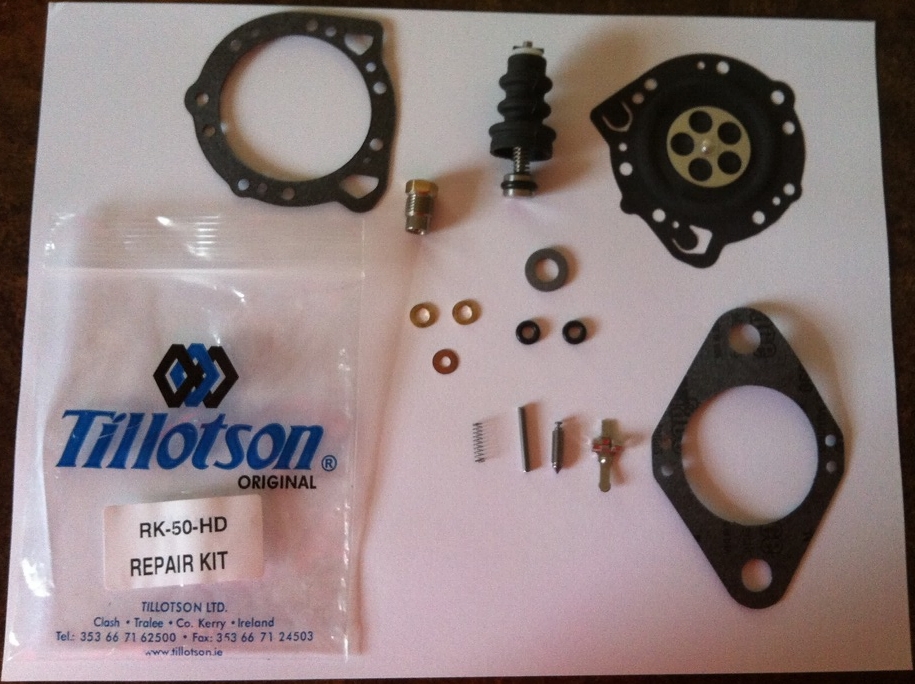 |
| Tillotson Carburetor repair/ refresh kit74) |
Mikuni (XR-750 racing engines only)
1972-1980
Through 1980, XR-750 engines were equipped with a 36mm Round Slide75) Mikuni. Below is a chart of the standard jetting of these carbs. Final jetting may vary. 76)
| 36mm Carb Types | Main | Pilot | Needle | Needle Jet | Slide | Air Correction Jet |
| VM-36-1 VM-36-4 VM36/39 | 240 | 25 | 6F5 | 159-P4 | 2.0 | 1.0 |
1989-2003
Engine upgrades prompted HD to recommend the use of Mikuni's 38mm Flat Slide carburetor (not supplied with the engine kit). Recommended jetting chart below.77)
| 38mm Carb Types | Main | Pilot | Needle | Needle Jet | Slide |
| TM38-85 (47mm spigot dia.) TM38-86 (43mm spigot dia.) | 210-260 | 20-25 | 6FM46 | Q0,Q2,Q4 | 4.0 |
Bendix/ Zenith I6P12 Carb (1972-Early 1976)
- Model 16P12 (standard) is a horizontal plain tube type carb with a fuel bowl, single ring shaped float, an accelerator pump, idle mixture adjusting needle and a throttle stop screw for idle speed adjustment.78)
- The throttle body casting contains an integral venture and a fuel valve seat that is pressed into the body. The underside of the throttle body contains a long boss that the main jet and discharge tube assembly screw into with the end of the tube projecting up into the venture.79)
- Note for 1973 and earlier: The change letter (A or B) is stamped near the Basic Bendix carburetor part number (13609) for identifying carburetors with modifications. Idle tube 27749-72 (marked A) is standard on carbs marked with a change letter (A). Idle tube 27750-72 (marked B) is standard on carbs marked with change letter (B).80)
- Fuel Supply Stream: Fuel under pressure enters the float chamber through the fuel inlet and valve (needle and seat. The bowl fuel level is automatically maintained by the float which opens and closes the needle seat valve to supply varying fuel demands to the engine.81)
- Accelerator System: The accelerator pump controls the amount of additional fuel discharged into the air system upon sudden throttle opening and it consists of a pump assembly, accelerating jet, check valve and the mechanical linkage connected to the throttle shaft.82)
- Idle System: Fuel for idle is drawn in from the main metering well through the idle tube and is mixed in the channel leading to the idle discharge holes with air entering the idle air bleed. At low idle speed, throttle plate is positioned to expose only the #1 idle discharge hole to engine vacuum. Air is admitted to the idle channel through the #2, #3 and #4 (1972 and later) idle holes. Air mixes with the fuel/ air mixture in the channel and is discharged through the #1 idle hole. As the throttle plate is opened, the #2, #3 and finally the #4 hole begins discharging fuel/ air mixture to supply the increased fuel required for higher engine speeds. The idle needle regulates the fuel/ air mixture flowing thru #1 discharge hole. Turning the needle clockwise (in) leans out the mixture while turning counterclockwise (out) richens the mixture. The idle speed is set by adjusting the throttle stop screw instead of the idle adjusting needle.83)
- Choke System: Before cranking the engine, the throttle should be opened to expose all three idle holes. The choke plate should be held fully closed during the cranking. After the engine starts, open the choke slightly. A hole in the choke plate helps prevent over-choking when the engine is started. The choke should be moved to wide open when the engine is partially warmed up.84)
- High Speed metering System: The fuel for the engine operation from off-idle to full throttle is supplied from the fuel bowl through the main metering jet, metering well and discharge tube. As the fuel flows thru the metering well and tube, it mixes with air entering the well vent to provide the correct fuel/ air mixture ratio for all engine speeds and loads. A series of air bleed holes in the discharge tube permits air from the well vent to enter the bowl below the level of the fuel in the float chamber. This reduces the average density of the fuel and enables it to flow freely at low suction. At high engine speeds, (and high suction), the air to fuel proportion thru the main metering system is reduced to provide a richer mixture needed for peak performance. 85)
- Features: 86)
| Year Model XLH/ XLCH | Serial Number | Main Jet Sizes (mm) | Low Speed Idle Jet |
|---|---|---|---|
| 1972-Early 1975 | 27155-72 89) | 0.90mm | Part #(27749-72) 90) |
| 1972-Early 1975 | 27155-72A 91) | '72-early '75 (0.95), '72-74 (1.00,1.05, 1.10, 1.15, 1.20, 1.25mm) | Late '72-'74 Part #(27750-72)92) |
| 1975-Early 1976 | 27155-72B93) | 0.95, 1.00,1.05, 1.10, 1.15, 1.20 mm 94) |
| Carb Idle Speed | 700- 900 RPM 95) | ||
Keihin Carbs Used on Evo Sportsters from 1986-2006 by Serial Number
- All data compiled from HD Sportster Parts Catalogs unless otherwise noted
- All CV models come equipped with accelerator pump unless noted.
- The Serial Number on CV carbs is labeled on the adjacent side to the accelerator pump linkage
Example 27231-98 translates to
| Keihin HD Serial Number | Year of Introduction | Notes |
| 27231 | 1998 | Can be used on same year and / or future multiple models |
| Keihin non-CV 1986 - 1987 | |||
| Carburetor Serial Number | Installed On All Models |
||
|---|---|---|---|
| 27501-86A (B83H | (86-87) - XLH 883 All Models Domestic and California | ||
| 27502-86B (B83H) | (86-87) - XLH 1100 All Models Domestic and California | ||
| Keihin CV 1988 - 2006 | |||
| Carburetor Serial Number | Installed On Domestic models Year - Model | Installed On California models Year - Model | Installed On Export models Year - Model |
| 27031-95 | (95) - HDI 883 Deluxe (95-97) - HDI 883, 883 Hug (99-2000) - HDI 883, 883 Hug, 883C (01) - Aust 883, 883 Hug, 883C |
||
| 27031-95A | (98) - HDI 883, 883 Hug (02-03) - Aust 883, 883 Hug, 883C, 883R |
||
| 27076-95 | (95-97)- HDI 1200 (96-97) - HDI 1200C, 1200S (99-01) - HDI 1200, 1200C (01) - Aust, Eng, Japan 1200, 1200C |
||
| 27076-95A | (02-03) - HDI, Aust, Eng, Japan 1200, 1200C | ||
| 27465-01 | (01) - HDI, Eng, Japan 883, 883 Hug, 883C | ||
| 27465-01A | (02-03) - HDI, Eng, Japan 883, 883 Hug, 883C, 883R | ||
| 27465-04 | (04-06) - HDI 883, 883C (05-06) - 883L, 883R |
||
| 27076-95A | (98) - HDI 1200, 1200C | ||
| 27480-97 | (97) - 1200, 1200C, 1200S (99-01) - 1200, 1200C | ||
| 27480-97A | (98) - 1200, 1200C (02-03) - 1200, 1200C | ||
| 27486-92 | (92-Early 93) - 1200 | ||
| 27486-92A | (93-94) - 1200 | ||
| 27486-92B | (95) - 1200 | ||
| 27487-92 | (92-94) - 1200 | ||
| 27487-92A | (95) - 1200 | ||
| 27488-92 | (92-Early 93) - 883 | ||
| 27488-92A | (Late 93-94) - 883 | ||
| 27488-92B | (95) - 883 | ||
| 27489-92 | (92-94) - 883 All Models | ||
| 27489-92A | (95) 883 All Models | ||
| 27490-96 | (96-97) - 883, 883 Hug (99-01) - 883, 883 Hug, 883C | ||
| 27490-96A | (98) - 883, 883 Hug (Late 98) - 883C (02-03) - 883, 883 Hug, 883C, 883R | ||
| 27490-04 | (04-06) - 883, 883C (05-06) - 883L, 883R | ||
| 27491-89 No Accel Pump | (89-90) - Swiss 1200 | ||
| 27491-96 | (96) - 1200, 1200C, 1200S | ||
| 27492-89 No Accel Pump | 89-90) - Swiss 883 All Models | ||
| 27495-96 | (96-97)- 883, 883 Hug (99-01) - 883, 883 Hug, 883C | ||
| 27495-96A | (98) - 883, 883 Hug (Late 98) - 883C (02-03) - 883, 883 Hug, 883C, 883R | ||
| 27495-04 | (04-05) - 883, 883C (05) - 883L, 883R | ||
| 27498-96 | (96-97) - 1200, 1200C, 1200S (99-01) - 1200, 1200C | ||
| 27498-96A | (98) - 1200, 1200C (02-03) - 1200, 1200C | ||
| 27501-88 No Accel Pump | (88-90) - 883 All Models | (89-90) - HDI 883 All Models | |
| 27501-89 | (89-90) - 883 All Models (90) - 1200 | ||
| 27501-89A | (91) - All Models | ||
| 27502-88 No Accel Pump | (88-90) - 1200 | (89-90) - HDI 1200 | |
| 27502-89 | (89) - 1200 | ||
| 27503-88 No Accel Pump | (88) - 1200 | ||
| 27503-88A | (89-90) - 1200 | ||
| 27503-88B | (91) - All Models | (91) - Swiss All Models | |
| 27503-92 | (92) - HDI & Swiss All Models | ||
| 27503-92A | (93-94) - HDI & Swiss - All Models | ||
| 27503-92B | (95)- Swiss All Models | ||
| 27504-88 No Acell Pump | (88) - 883 All Models | ||
| 27504-88A | (89-90) - 1200 | ||
| 27731-98 | (99-01) - 1200S | ||
| 27731-98A) | (98) - 1200S (02-03) - 1200S | ||
| 27731-04 | (04-06) - 1200C, 1200R | ||
| 27732-98 | (99-01) - 1200S | ||
| 27732-98A | (98) - 1200S \ (02-03) - 1200S | ||
| 27732-04 | (04-06) - 1200C, 1200R | ||
| 27733-98 | (98) - Swiss 1200S | ||
| 27734-98 | (98-2000) - HDI 1200S | ||
| 27749-01 | (01) - HDI, Aust, Eng, Japan 1200S | ||
| 27749-01A | (02-03) - HDI, Aust, Eng, Japan 1200S | ||
| 27749-04 | (04-06) - HDI 1200C,1200R | ||
PERFORMANCE OPTIONS
Keihin BD
- Used in the Screaming Eagle Package line from HD as an Evolution XLH HI-FLO Carburetor & Air Cleaner.
- Adjustable Accelerator Pump stroke
- Incorporated a special intake manifold to carb spacer that had to be drilled and tapped (1/4 x 28) in the side for included Voes connection adapter
- Required a 1987 replacement style intake manifold for 1988 and up models
- Required possible grinding of the right rear corner of the front cylinder head, due to interference with the carburetor throttle pulley and cable guides, for proper clearance 96)
| Carb #27001-88 | |||||
|---|---|---|---|---|---|
| Slow Jet Part No. | Size (mm) | Intermediate Air / Fuel Part No. | Size | Main Jet | Size |
| 27383-88 | 42 | 27113-87 | Blank* | 27106-85 | 1.30 |
| 27302-84 | 50 | 27109-87 | 55 | 27107-85 | 1.35 |
| 27329-83 | 52 | 27172-89 | 60* | 27149-85 | 1.40 |
| 27284-85 | 55 | 27110-87 | 80 | 27151-85 | 1.45 |
| 27310-85 | 58 | 27111-87 | 1.00 | 27150-85 | 1.50 |
| 27318-85 | 60 | 27112-87 | 1.20 | 27108-87 | 1.60* |
| 27283-85 | 62 | 27173-89 | 1.70 | 27119-88 | 1.65 |
| 27896-79 | 65 | 27134-89 | 1.70 | ||
| 27894-78 | 68* | ||||
| 27895-87 | 70 | ||||
| 27897-78 | 72 | ||||
*in carburetor
—-
Aftermarket Carburetors
1970s Era- Lake Injector
- Originally made for airplanes, the Lake injector was a popular fuel delivery system in the 70s era. It was designed for the ultimate in performance with a minimum of tuning effort. Don't confuse the word “injector” with fuel injection, as these series of carburetors are not a fuel injector or a fuel injector body98). The body design, plus the velocity stack in unison with the throttle slide, forms a venture which enables the injector to achieve a good fuel/ air mixture. 99)
- The manufacturer claimed a 15% - 25% or more increase in horsepower, unequalled acceleration, immediate starts and instant tuning.
- Installation was a simple bolt on design with no modifications needed.
- Suitable for 883s as well as 1000 model Sportsters although could be installed on Shovels, Pans, Triumphs and Hondas.
- Body options for an extra price include, show chrome, bright anodized and 24K Gold.
- A true low head, nil pressure injector as does not depend on venture suction like a carb but just pure air mass flow, so it self corrects for great altitude manifold pressure changes.100)
- You wont fine tune this nail in a tube, they run rich when the tanks full, and get lean as the fuel drops.101)
- Many people have to plumb air supply to the tank with a 'pop off' to keep pressure head constant below 1 PSI.102)
- The unit is gravity feed instead of having a fuel pump for delivery and it was prone to leaking if you left the petcock open.103)
- Posa and Star are all very similar and found their way from small aircraft and onto bikes.104)
- POSA, Lake Injector, Revflow and Aero Carb are all float-less, diaphragm-less carburetors.
- These carbs do not operate well on more than .5 lbs of fuel pressure yes that is less than half a pound of fuel pressure. These carbs do not vent any fuel vapor that may form in the body to the venturi as there is not float bowl well or diaphragm vent.105)
How to adjust the carb for all throttle positions
- Tools needed: Screwdriver, #16 nail sharpened, small jar, syringe or breaker graduated in cc's or ounces, gloves, small wood throttle blocks (you'll make these), fire extinguisher rated for fuel.
- Instruments needed:106)
- Manifold pressure gauge, EGT gauge or air/fuel ratio gauge.
- So you have followed the manufacturer's directions to adjust your POSA style carburetor but find that you still have rich or lean spots across the range of throttle and you're frustrated. The following procedures to set the carb correctly takes about 4 hours of measuring and tuning.107)
- The fuel in the tank should be half full (a full tank of fuel will make the carb run richer and an almost empty tank will run leaner). Remember that you are operating on .022 pound of pressure per inch of vertical fuel column. For simplicity say our tank is only 6“ tall. If we have used a half a tank of fuel we now have used 3” of fuel and have a 9“ drop to the carb. So, 9 x .022 = .198 lbs of fuel pressure. Less than a quarter of a pound.
- You need to pick 6 throttle positions and be able to repeat the positions. Use idle, 1500, 2000, 2500, 3000, and wide open throttle. With the carb set as best as you can get it, make a stop block that you can put in the throttle so you can accurately repeat each position. The rpm will change when you adjust the carb down the road. We simply need to be able to repeat the position. You can use a piece of wood that has a hole drilled through it that is the throttle shafts diameter. Split the piece of wood in the center of the hole. The length of the wood will vary for each throttle setting.
- At each throttle setting, use the needle to adjust the carb so the engine runs that absolute best at each station, regardless as to how it runs anywhere else. Make note of the manifold pressure and egt/or air fuel ratio when the carb is set for each station. Once you have a single station set perfectly with the needle, turn the fuel on and let fuel flow out of the carb in to the bowl for 1 minute. Measure the amount and record it next to the egt/air fuel ratio and manifold pressure reading.
- Repeat step 3 for all 6 stations, recording manifold pressure and rpm along with egt/air fuel ratio. Measure fuel flow for each individual station and record the measurement. Note: this process will consume about 1 gallon of fuel. You need to keep the fuel in the tank as close to a constant fuel level as possible.
- Now that you have made a chart that show the fuel flow out of the carb at each station where you set the carb so that the engine ran it's best, you need to set the needle so the carb runs the best at idle. This will be the permanent setting for the needle. Idle position to about 1500 rpm is the most important throttle range.
- Now go back to each throttle position using your blocks of wood and re-measure the fuel out of the carb. In most cases it will be less than you originally measured it. So to bring the fuel flow up the same level you make a vertical mark along the flat of the needle where the needle goes into the fuel orifice. Just use a black fine line marker to do this.
- Remove the needle. Now use the sharp nail and make a scratch mark along the horizontal axis of the needle 1/8” on both sides of the vertical mark. When satisfied with the depth, reinstall the needle and measure the fuel flow. You want it to be equal to what it was in steps #3 and 4.
- This is the trial and error time consuming part of the job. Be cautioned that a little scratch for starters is better than a deep one. It does not take a very deep mark to allow a lot more fuel to flow.
- When you are done with each station you will have a series of scratched that are not connected. You may find that in some areas of the needle you won't have to do much and in others you will have to have a deep scratches and you may need to connect the scratches with another scratch.
- The top and bottom ends are critical. For the top end or wide open throttle, this is where the egt comes in handy. At wide open throttle, the engine should run about 50 to 100 degrees rich of peak. When you throttle back to 75% power the egt should rise.
- When set correctly, you should be able to see a steady rise in the egt from idle to just before full power. At full power, the egt should dip slightly.
- Note: in the event that the needle is rich at the bottom end instead of lean over the range, you will have to go to the next smallest needle and start the procedure again. It is very difficult to make a needle leaner without adding material to the needle.
- On POSA style carbs (Revflow, AeroCarb) equipped with mixture control, set the mixture control so that is just shy of being full rich when doing the above needle work. In the event that you need to make the carburetor slightly richer, you can do so without having to go through the entire measure, scratch, measure, scratch scenario all over again. As you burn off fuel, the fuel pressure is less so you may need to go “over rich” to compensate for less pressure at the needle.
- The air/fuel ratio meter should read as follows:
- Cold start to warm idle 800 rpm
- Idle 800-1000 rpm
- Mid range 1000-2500 rpm
- Cruise 2700-3300 rpm
- Wide open throttle108)
- This type of fuel delivery is still being used in aircraft. However, it has now evolved into more of a fuel injector that you are probably used to in principle. Although it is similar in looks, it has a slightly negative pressurized TBI with constant feed aviation fuel. So, unless your setup for jet fuel, these won't work on Sportys.
- This is from Ellison Fluid Systems:
- The EPA has required the oil companies to add oxygenates to auto fuel in many parts of the country to reduce pollution in the winter months. In most areas this additive is alcohol which will damage aircraft fuel systems. In addition to possible chemical incompatibility, the high vapor pressure of auto fuel can be a problem when used in aircraft, as it is much more likely to boil than aviation fuel. Unlike aviation fuel, the formula of auto fuel is altered as the seasons change, so winter grade fuel is even more likely to form vapor.
- Many of our customers have stated that they believe there is no chemical difference between aviation fuel and auto fuel. A dramatic difference can be demonstrated by pouring a sample of each into Styrofoam coffee cups. The aviation fuel will remain contained in the cup, but auto fuel will dissolve the cup and flow right through the bottom, as it will destroy rubber parts in the TBIs. 109)
Bendix Stromberg Carburetor Identification
- Bendix Stromberg used a unique identification scheme where a series of letters and numbers were assembled to identify and describe how a carburetor was constructed. The first two letters described the carburetor design, followed by a number that identified the size, and numbers and letters to identify specific design details and modifications.
- The first (two) letter(s) comprise a Basic Design Code that places the Bendix Stromberg carburetor in a design category, where:
- A – Pressure Injection Carburetors
- E – Pressure Injection Carburetors
- NA – Float-Type Carburetors
- P – Pressure Injection Carburetors
- Q – Pressure Injection Carburetors
- R – Fuel Injection Systems
- S – Speed Density Metering Systems
- Example: NA-R9G
- Prefix- “NA” – for float-type carburetors followed by a “-”(dash)
- The next letter indicates type, where
- S – Single venturi updraft designed for two, three and four cylinder engines in the 25~95 hp class. NOT fitted with economizer, acceleration pump or mixture controls.
- R – Single venturi updraft, designed for engines of all types in the 50-400 hp class. All are similar in design and incorporate needle valve type mixture control, accelerator pump and economizer. Some bodies are interchangeable in this series and deferent design economizers are used.
- D – Double updraft venturi, with the float chamber to the rear, was considered obsolete c.1930
- U – Double updraft venturi, with the float chamber between barrels. See specific models for details.
- Y – Double vertical venturi (updraft), with two float chambers fore/aft of barrels. See specific models for details.
- L – Inverted, down draft venturi.
- T – Triple venturi, double float chamber fore/aft of barrels. The NA-T4 series is the only known model. Designed for use on Wright J-5 and other 9-cylinder radials, where each venturi feeds three cylinders. It has float similar to Y series, but with back suction mixture control. No economizer or accelerator pump.
- F – Four-venturi with two separate float chambers. The last letter and numbers indicate a specific model.
Intake Manifold
| 1972-Early 1976 | 27021-71A |
| 1966-1971 | 27021-57 |
11)
1952-1959 HD Spare Parts Catalog pg 16
13)
, 16)
, 19)
, 22)
, 25)
, 27)
, 29)
thefrenchowl from the XLFORUM http://xlforum.net/vbportal/forums/showthread.php?t=691253&highlight=Linkert&page=2
32)
thefrenchowl from the XLFORUM http://xlforum.net/vbportal/forums/showthread.php?=691253&highlight=Linkert&page=2
42)
, 44)
, 45)
, 46)
, 47)
, 48)
DR DICK of the XLFORUM http://xlforum.net/vbportal/forums/showpost.php?p=5287605&postcount=31
43)
Zaemo of the XLFORUM http://xlforum.net/vbportal/forums/showpost.php?p=5287605&postcount=31
49)
, 50)
, 51)
DR DICK of the XLFORUM http://xlforum.net/vbportal/forums/showthread.php?t=1993187&highlight=linkert
56)
, 59)
, 60)
, 61)
, 62)
, 63)
, 64)
, 65)
, 78)
, 79)
, 80)
, 81)
, 82)
, 83)
, 84)
, 85)
1970-1978 HD XL/XLH/XLCH/XLT 1000 FSM
66)
1959-1985 Clymer Sportster Service and Repair Manual pg 76
67)
HD Sportster Parts Catalog (99451-78B)
69)
1970-2010 Haynes Sportster Service and Repair Manual pg 3.1
74)
Pic courtesy of The Doctor71 of the XLFORUM
86)
1959-1985 Clymer Sportster Service and Repair Manual pg 78
87)
HD XLH,XLCH-1000 Parts Catalog (99451-78B)
92)
HD Sportster Parts Catalog pg 28 (99451-78B)