Table of Contents
This is an old revision of the document!

REF: Electrical System
* See also Illustrated Stock Wiring Diagrams in the Ironhead Section of the Sportsterpedia.
Ironhead - Simplified (Customized) Wiring Schematics
Minimal Configuration (w/Ultima Module)
The following wiring diagram is a minimal config - No Starter - No Turn Signals - No Front Brake Switch - No Kill Switch.
The ignition module is an Ultima version and fits in the nosecone where previously only the cam sensor plate was mounted. In this diagram the Ultima Single-Fire Configuration is used, feeding separate trigger signals to the dual coils to fire the front & rear spark plugs separately (the Ultima BLUE wire fires the front coil & the Ultima PINK wire fires the rear coil).
If you choose to use a dual-fire configuration of the Ultima ignition, it will also work when you pair it to the appropriate dual-fire coil. In that case, you will only use the Ultima PINK wire to fire the selected dual-fire coil. (The Ultima BLUE wire will not be used at all with a dual-fire version.)
Using the VOES connection with either configuration (which helps with idle & cruising spark timing by providing more advance) is recommended by connecting the Ultima VIOLET wire to the VOES unit.
Implementing a tachometer is optional. If used, the Ultima GREEN wire will connect to the tachometer signal input wire. The tach will also need a ground connection on the bike and key-operated power for the tach light.
There are only six wire colors to minimize wire purchase: Black - White - Red - Blue - Yellow - Green. There are enough colors so that no connecting point should have the same color twice in order to make it easier to know which device is connected to/from another device.
This circuit uses the Frame/Engine for ground conduction. Be sure you have good ground points at the needed locations or run a separate black wire to those locations to assure a good ground.
Beware that the brake light shares the same fuse as the ignition circuit - So, if you have a short to ground in the brake circuit it will blow the fuse & kill the ignition. You could add a separate fuse for the brake light to avoid that potential problem.
The diagram shows an optional Gen Light, implemented with a diode and an incandescent bulb.
To implement the VOES, add it with a vacuum hose to the carb - then wire the single VOES wire into the Violet Wire of the Ultima ignition module.
To implement a tachometer, use a normal HD dual-fire tach and wire the input signal to the Green Wire of the Ultima module.

Other Simplified Wiring Diagrams
( CLICK ON THE DIAGRAM to get a larger version to display )
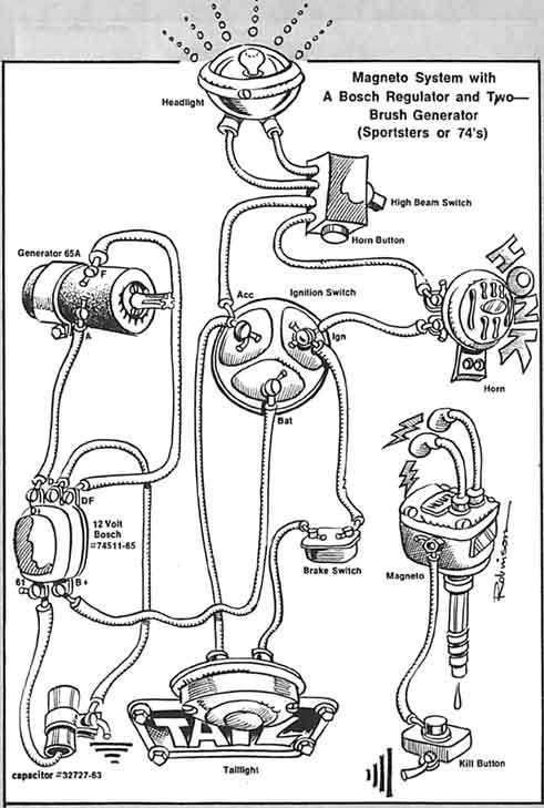
| Wiring for Magneto Fired Sportsters 1) |

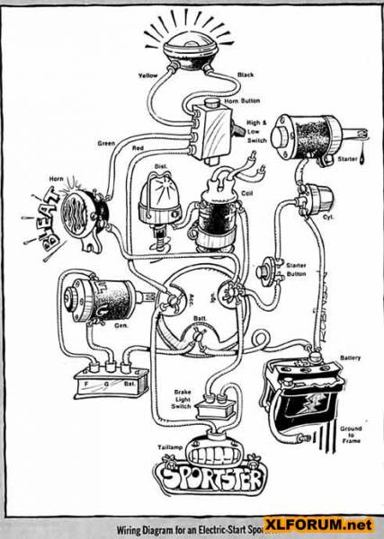
| Wiring for an Electric Start Sportster 2) |
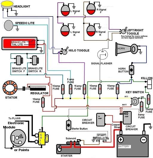
| Generic HD Wiring Diagram 3) |
| Ironhead CAD Wiring Diagram ('77) 4) |
