Table of Contents
This is an old revision of the document!

REF: Engine Control - Sub-01a
Sportster Sport 1200S '98-'03 Ignition Replacement
Changing to an after market ignition system is something that will probably come to all 1200S owners eventually as stock and SE ignition components become more difficult to source. 1) PLEASE NOTE: by doing this mod, you will lose certain functions from the 1200S. Specifically, the diagnostic (fault code) function and the related check-engine light on the speedo, which are both tied into the stock ignition module. The frame-mount Sportster electrical system is so basic (and this modification will make it even more simple), that a diagnostic sytem with data-link can be considered more or less redundant.
Swapping the ignition module means you also have to swap the coils, as most aftermarket systems require coils with a 3 ohm primary resistance, compared to 0.5 ohm for the stock 1200S coils.
Parts
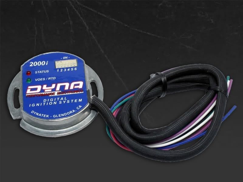
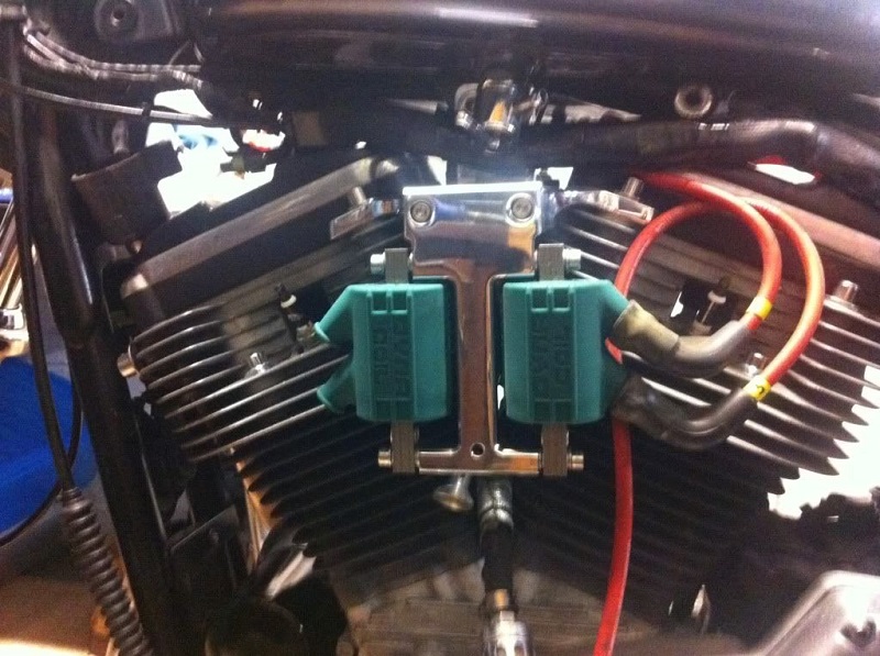
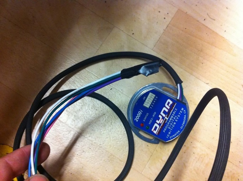
The ignition used below is the Dynatek D2Ki-3P, which comes with two traditional style Dyna DC1-1 twin-post coils.
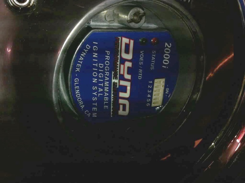
The Dynatek module has switches on the front to pick different advance curves.
For about another $120 you can get a programming kit with harness (when you plug in the programmer, you can upload a map and disable the switches on the module).
But one of Dynatek's (very helpful) reps advised to try the switches first - he said that among the range available there should be a curve to suit most bikes.
Note from Daytona Twin Tec's website:
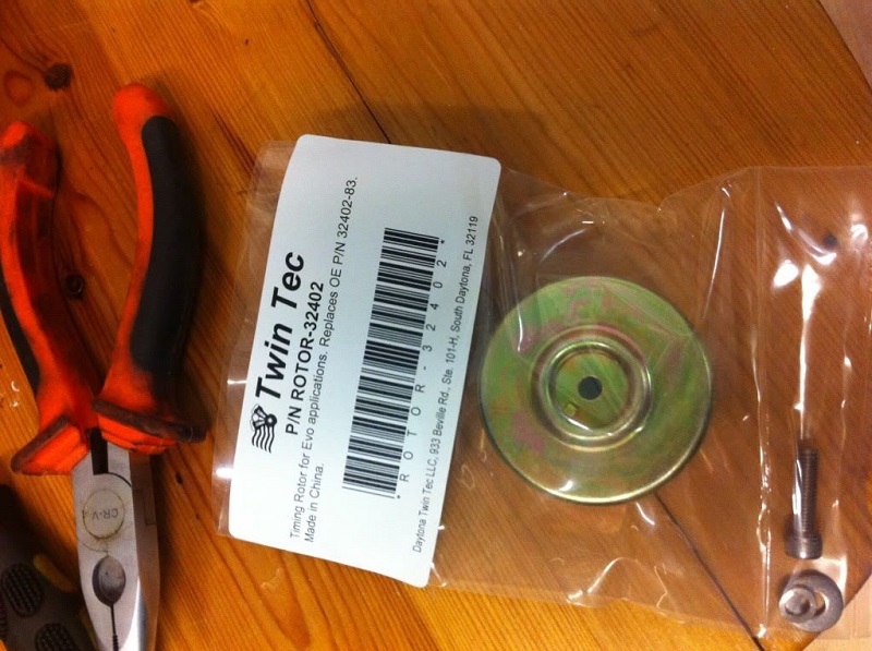
The Sportster 1200S model with dual plug heads comes with a special ignition module, similar to that used on Twin-Cam 88® models. If you require a programmable aftermarket ignition for the 1200S, you can use the Model 1005 EX version (not the 1005S). The Model 1005 mounts in the nose cone. The original equipment coil has low resistance primary windings that are not compatible with the Model 1005. You must replace the original equipment coil with an aftermarket four tower coil, such as the Dyna DC6-4, that has 3 ohm primary resistance. Please refer to our Dual Spark Plug Tech Note for more details. You will have to remove the original equipment MAP sensor. You will also require our timing rotor (P/N ROTOR-32402) and VOES switch (P/N VOES-KIT-MC7).
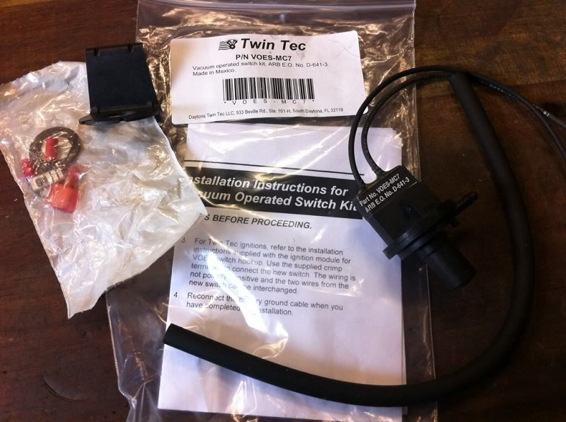
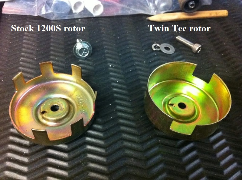
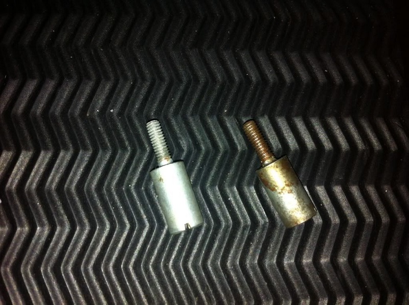
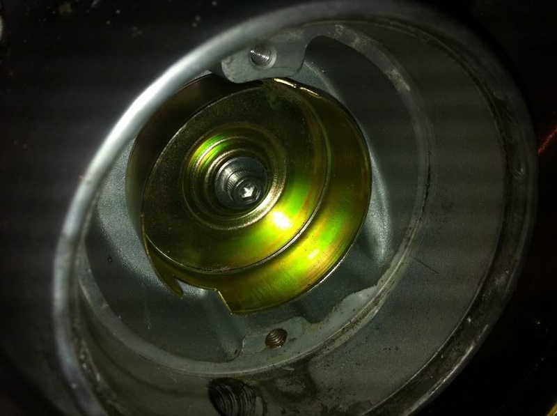
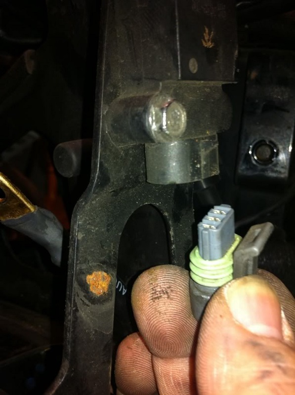
A Daytona Twin Tec VOES kit was used to replace the MAP sensor. This is set at 6-7 in-Hg, instead of the stock 3.5-4.5 In-Hg, to reduce spark knock during light load and throttle roll-on. The kit comes with mounting bracket, electrical connectors, instructions and a new hose then coupled with their timing rotor, which is basically the stock rotor for most Harleys except the 1200S. See rotor comparison on right pic below.
Remove the stock ignition parts
With the tank and seat removed, it's time to start stripping a few parts that won't be needed any more.
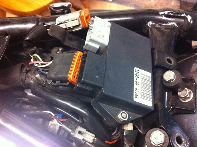
First, the stock ignition module and its mounting bracket. Remove the bolts from the two well nuts in the frame cross rail. Both of these will go, along with the two large Deutsch connectors.
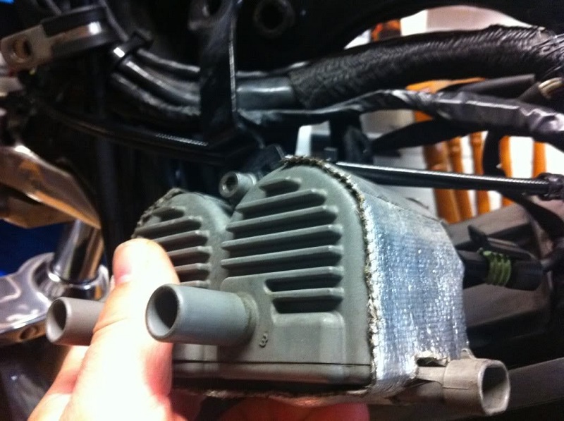
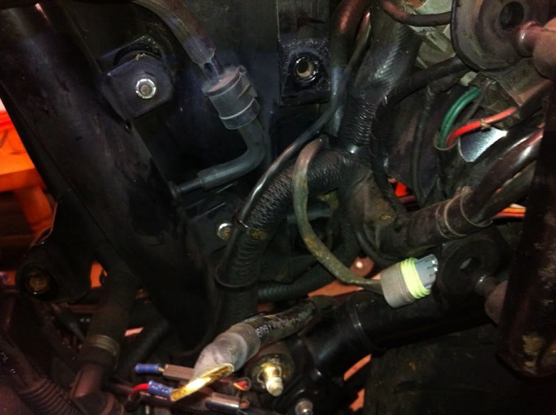
Then remove the stock coil, it's mounting bracket and the MAP sensor.
The mounting bracket for the MAP sensor is glued to the frame.
It also serves as a mount for a “spare” electrical connector for the air filter trapdoor solenoid on bikes registered in California.
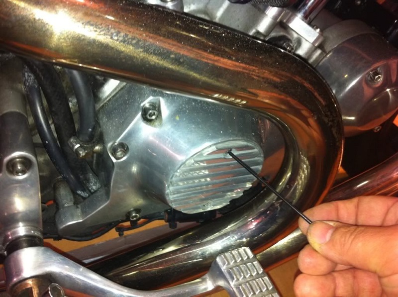
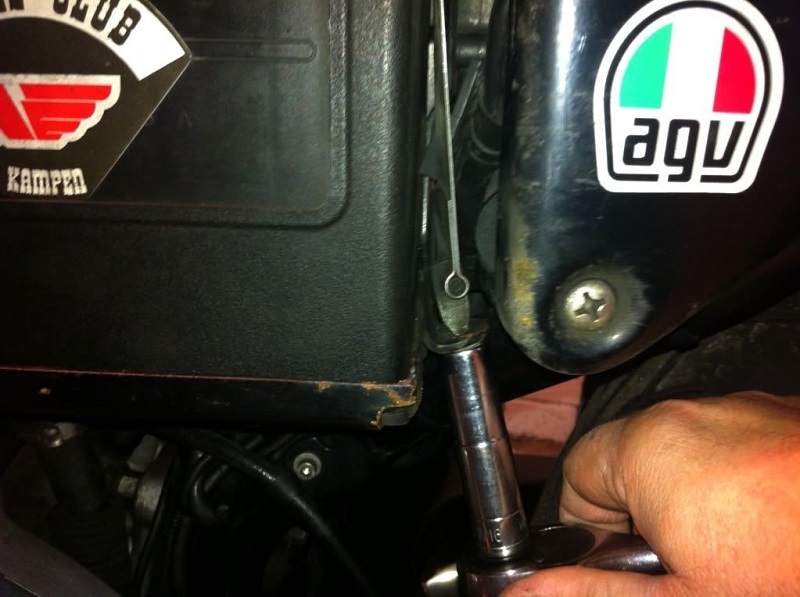
Remove the ignition cover to get to the stock ignition pick-up and timing rotor (if you have a stock cover, you'll need to drill out the two pop rivets that hold it in place).
When replacing with rivets, ensure you use the sealed back pop rivets from HD, or it's possible the center of the rivets could come adrift and wreck your ignition unit and rotor.
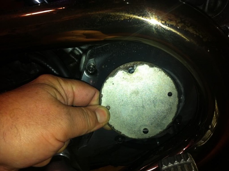
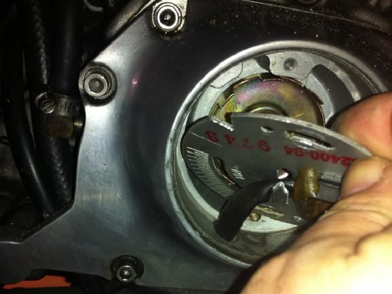
If you drilled out the rivets on your stock cover, you'll find an inner cover behind it, held on by two countersunk screws.
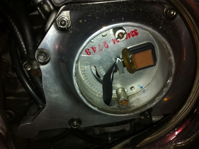
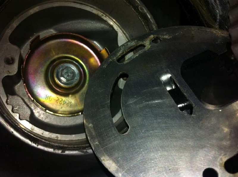
Remove them along with the backing plate to reveal the ignition pick-up.
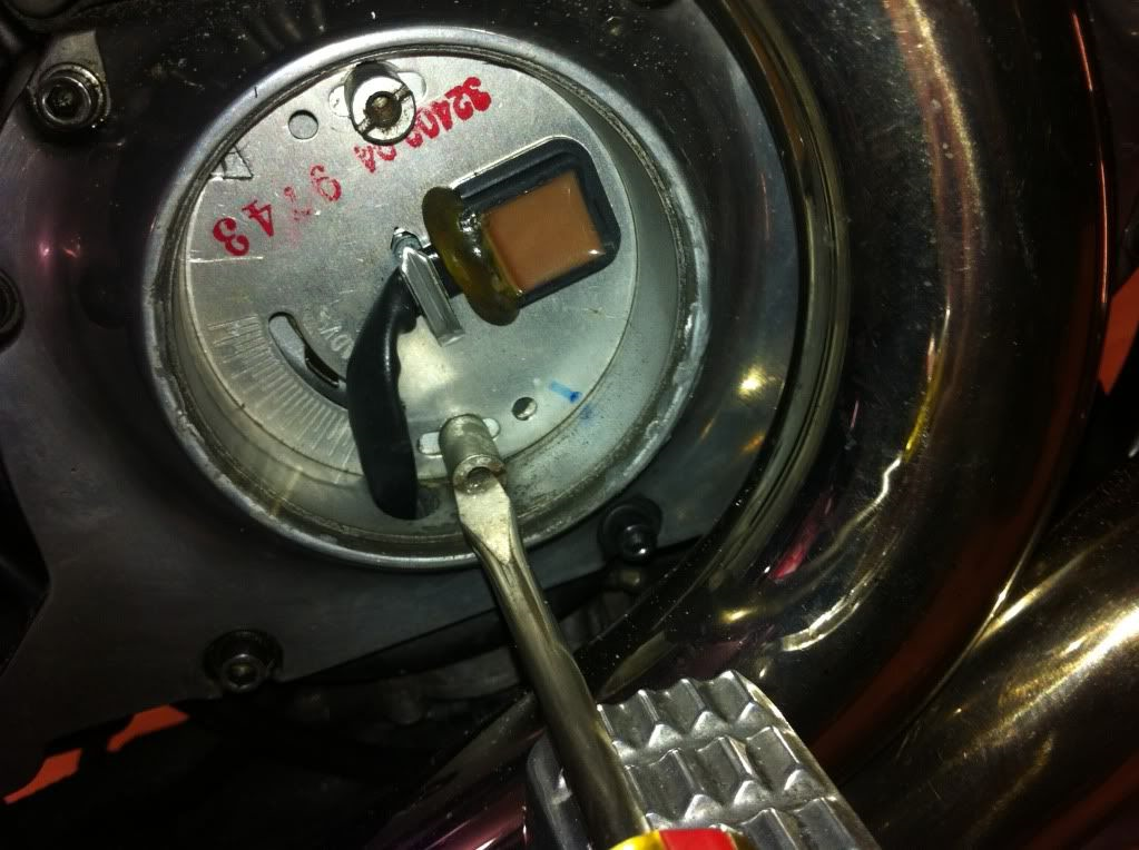
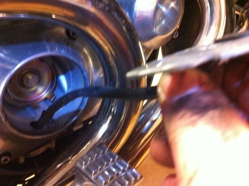
With a flat-head screwdriver, remove the two pillar bolts holding the pick-up in place and pry out the pickup to reveal the ignition rotor behind it.
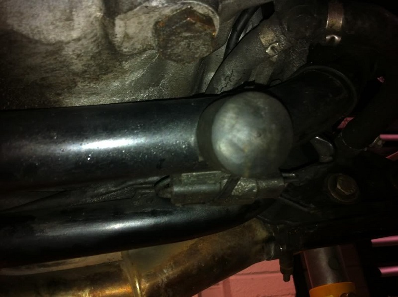
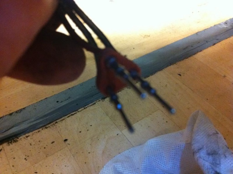
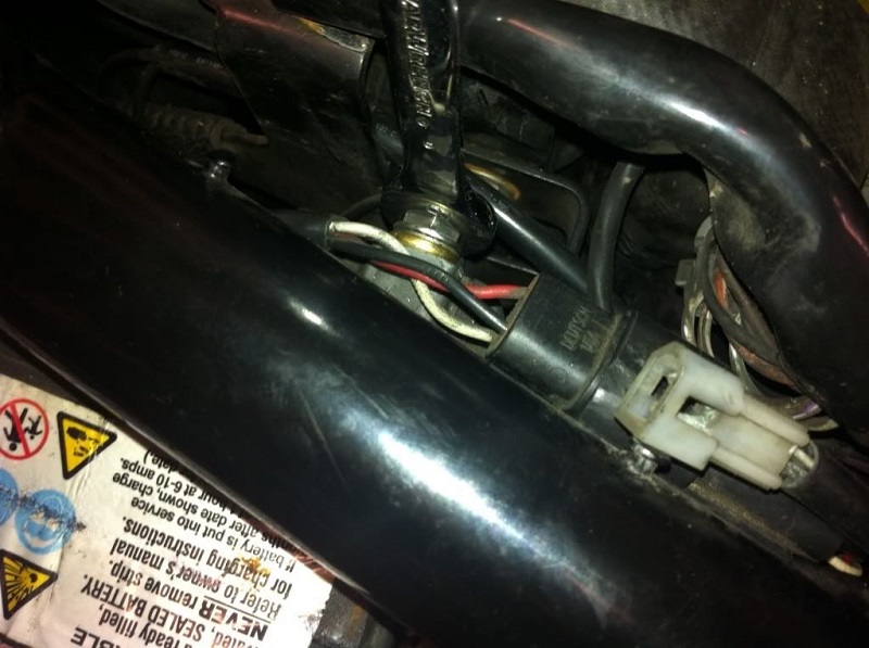
Unclip and disconnect the three-pin Deutsch connector clipped to the rear of the bottom frame rail.
These are the leads to / from the pick-up. It's just below the sidestand bump stop.
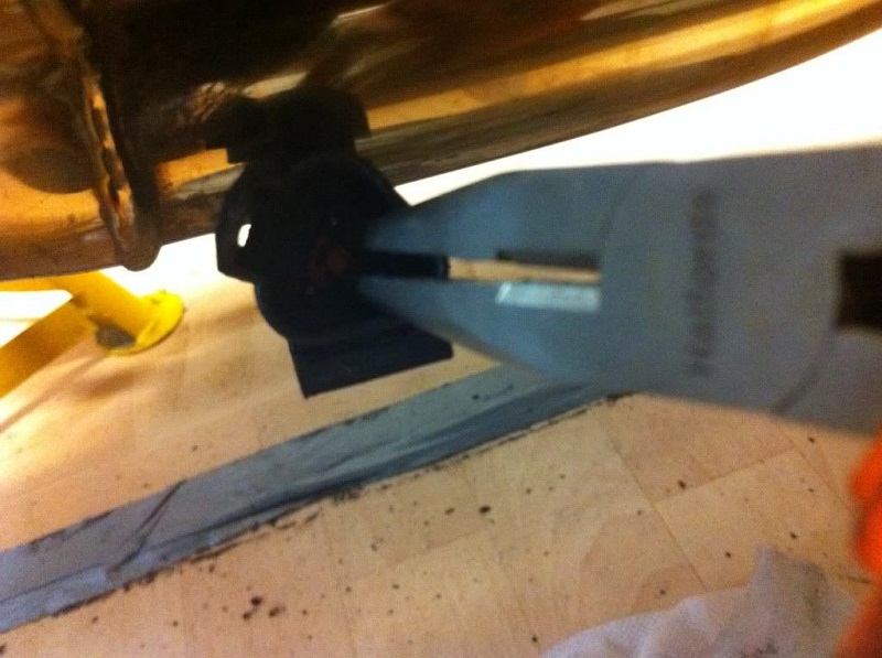
With a pair of thin-nose pliers, remove the orange plastic lock piece from inside the connector.
With a small pointy object, hold back the plastic lock tab holding each crimped connector inside the block, whie you push the connector outwards. When all three crimped connectors are clear of the lock tabs, carefully pull them out of the back of the connector; then remove the rubber sealing bung.
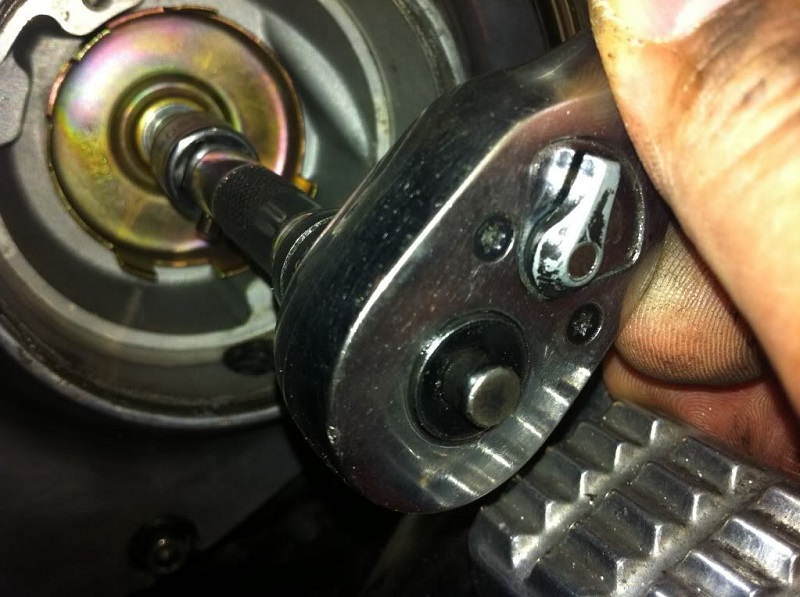
Then remove the bolt holding the ignition rotor in place and remove the rotor. It will probably be quite stiff to pull out, but gently work it side-to-side to get it moving.
Install the new parts
Fit the new rotor and screw. The Twin Tec rotor came with an Allen screw, washer and lock washer. Also, use Loctite 243 on the screw.
This is not a bolt that you want to come loose! Torque to 43-48 inch-lbs / 4.9-5.4 Nm.
Tape the wire ends of the Dynatek ignition module to make it easier to feed them through the cam cover.
Secure the module with the two pillar bolts. Don't re-fit the covers yet. Later you'll need to set the timing when all the electrics are connected up.
Time to attack the wiring loom. This is where it could get a little bit scary.
You can sit down first with a 1200S wiring diagram and work out what has to come out and where the new components would be connected or spliced in.
This should do away with about a dozen wires from the main loom under the tank and all of the wires to the stock ignition module.
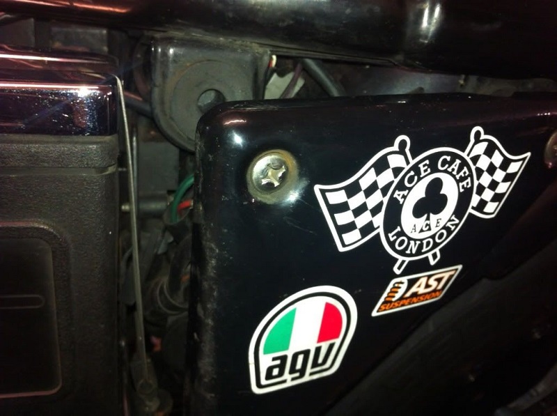
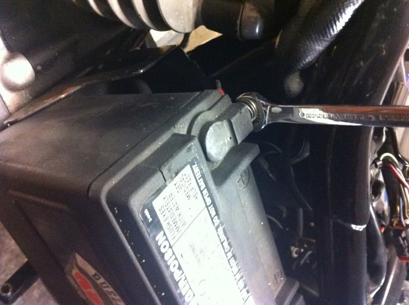
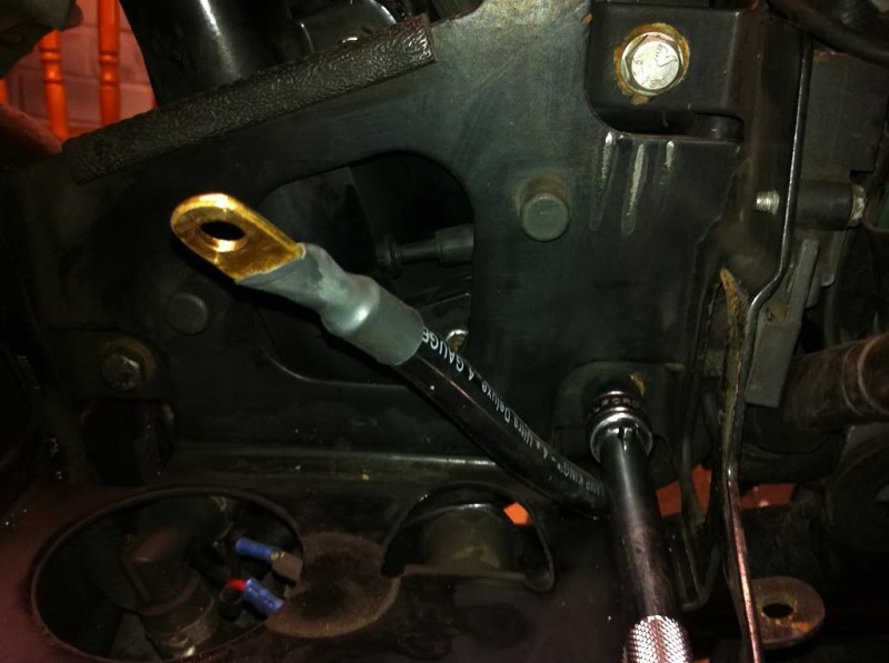
First, pop off the side cover behind the battery to remove the battery strap, cover and the ground cable from the battery.
Then slide the battery off the tray slightly to remove the positive cable.
With the battery out of the way, remove the rubber tray liner and the fasteners holding the battery tray in place (these three bolts, plus one nut under the tray).
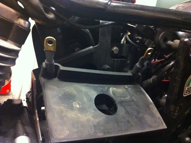
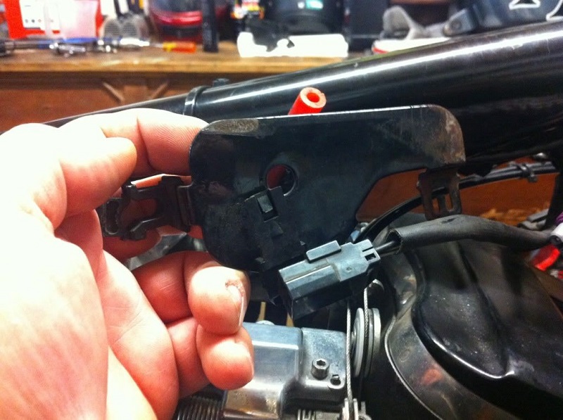
As you remove the battery tray, disconnect the bank angle sensor bolted to the rearward side of it.
The bank angle sensor will probably not be going back on. there may be a way to include it, but it's not obvious from the wiring diagram, so out it goes.
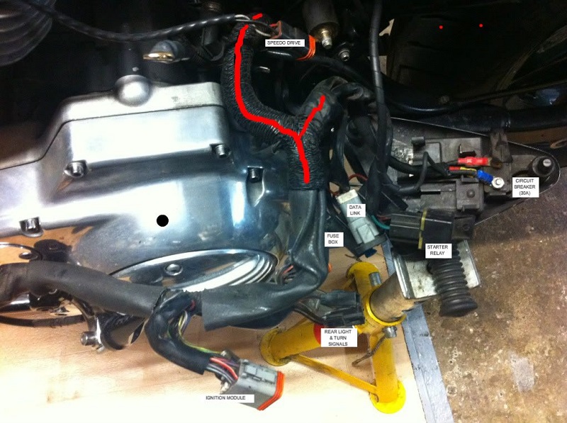
Removing the battery tray reveals the section of wiring loom behind it.
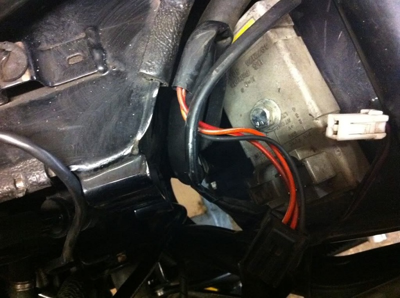
Remove the Deutsch connector for the speedo drive from the frame and disconnect it. Fold both ends out of the way, as this all needs to stay as it is.
Disconnect the wires to the rear lights and turn signals and the connector to the turn signal module that's bolted to the fender.
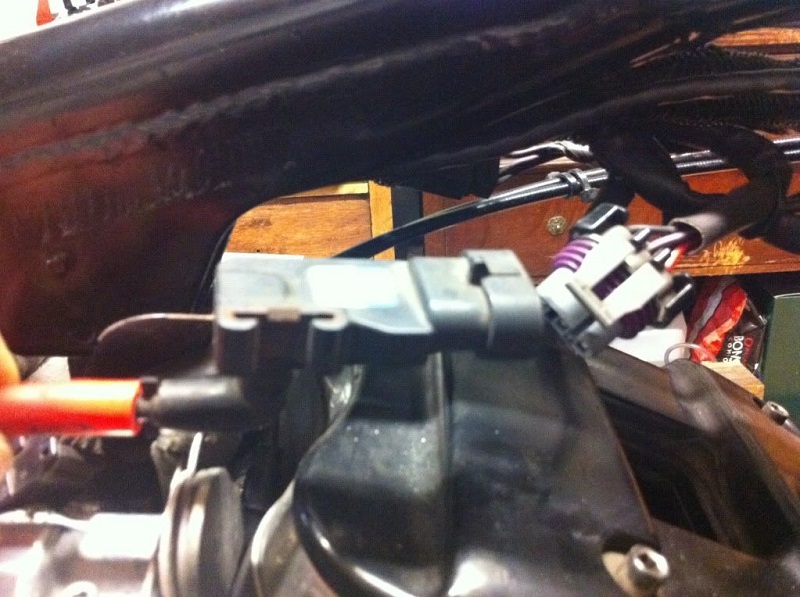
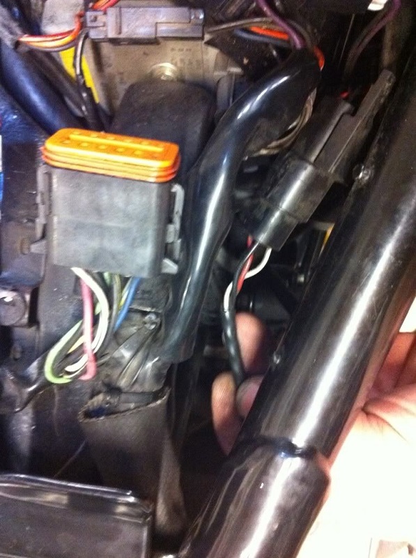
You can now pull out this section of loom to get access to it. The plastic mesh covering indicated in red will have to be removed to pull out the wires to the stock ignition module. Under it is a length of corrugated plastic sheathing.
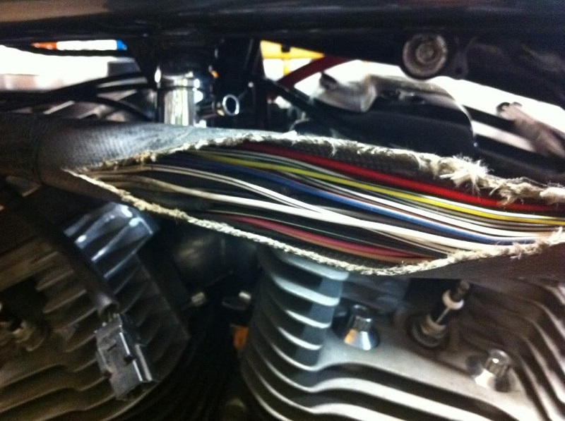
Back to the loom under the tank. The covering was cut to expose the wiring (much of which we are going to lose).
You don't need to cut the covering any further back than level with the rear mounting point for the gas tank.
But it does need to be opened up all the way forward and remove the plastic mesh around the point where the wires for the front turn signals, coil, MAP sensor and California trapdoor connector (if equipped) exit the loom, to be able to separate those wires and access the splices that are in that area.
This area is also where the connections will be made to the new coils and to the Dynatek ignition module.
Inside here are a bunch of large splices, which HD, in their infinite wisdom, chose to place close together and directly in line with the boss for the fuel tap, making the loom thickest at exactly the point where it's the tightest fit under the tank.