Table of Contents
This is an old revision of the document!

REF: Engine Mechanicals
Evo Crankcase Pressure and Engine Breathing
Crankcase Pressure
Crankcase air pressure is mainly generated by the up and down movement of the pistons.
The downstroke of the piston causes the volume underneath the pistons to decrease which puts pressure on the oil in the sump. 1)
This pressure is multi use;
- It helps to push sump oil up and out the scavenge passage to the return side of the oil pump.
(the scavenge side of the pump also pulls a vacuum on the sealed passage from the sump outlet to the pump) 2) - It also initiates the splash and mist process as the compressed air above the oil is ready to spring up when the piston rises.
Then the upstroke of the piston creates an upward vacuum bringing some of the oil from the sump with it.
With little to no (piston ring) blow-by and a check valve on the breather system;
Crankcase pressure is essentially cycling between atmospheric and negative (pressures) as the pistons go down and back up.
(remember, due to the common crankpin 45 degree design, a Harley motor is a variable volume crankcase, unlike most motors) 3)
This creates splash oil which is bounced about in the crankcase.
This also creates an air / oil mix when tiny particles intertwine with the oil in suspension.
The two don't actually mix as does sugar and water.
So separating them back apart is fairly easy if you add an obstacle for that 'mix' to collide into.
The obstacle is widely known as the breather or umbrella valve although anything the mix touches in the motor could accomplish the same thing in theory.
The piston motions create a pulsating blast of air pressure (push pull condition as each piston rises and falls).
Static oil pump pressure has already been dissipated by the time it reaches the crankcase.
(although it takes static oil pressure to get the oil from the pump to the crankcase)
Likewise, crankcase (CC) pressure will have a constant change in velocity.
Oil in the crankcase adds resistance to the air pressure generated (raising the pressure).
The movement of the pistons and flywheels splash oil around in the engine.
Gravity oil (from the drain ports in the heads) returns to the crankcase or gearcase (respective to year model);
- On 86-03 engines, gravity oil falls into the crankcase sump area.
- On 04 and up engines, gravity oil falls into the gearcase.
Blowby
Blowby pertains to the condition of ring seal at the cylinders / pistons. 4)
Neither new rings nor cylinder bores are perfectly round.
As a result, when you put a new ring on a piston and into a new bore, there's actually very little surface area of contact between the two.
The honing process puts a texture on the cylinder wall that allows the ring to machine the wall into the same shape as the ring during operation.
This increases the surface area of the contact patch.
The ring is said to be “seated” when it has carved the cylinder into it's shape and there's contact all the way around.
Many, many times I've pulled bikes apart and looked at the cylinder walls and spotted places where the ring was never touching it. 5)
It has a huge amount to do with the accuracy of the boring job as well as the accuracy of the rings used.
If it was bored perfectly and the ring was perfectly round, there would be no seating even needed.
Proper ring seating during break-in
There is a risk of ring microwelding by getting too aggressive in the break-in. 6)
HD's break-in procedure, and S&S's, and others are designed to minimize heat build-up.
Be gentle on the motor, don't put it in a situation that makes it hot.
The reason is simple.
With very little contact area between the rings and the cylinder walls;
Ring tension is concentrated and those areas that do make contact get very hot.
That localized heat can and will damage the piston, and remember, the ring land in the piston is a sealing surface.
Damage it and you'll never get a good ring seal.
This scenario happens more than you might think.
Good lubrication and a gentle break-in consisting of several heat cycles to begin with are absolutely mandatory on an Evo engine.
Ring seat depends on how good the machine work is.
If everything is perfect, it'll be seated when it's put together (it won't be though).
If the bore and/or rings are out of round badly enough they may never seat.
Normal blowby
In the absence of any blow-by getting past the rings, the crankcase alternates from atmospheric (pistons down) to a vacuum (pistons up). 7)
But in the real world, a little gets past the rings, so there's a net outflow equal to that.
Why Oil Pukes Out the Breather Vent
The real reason these things like to spit oil out the breather is because they're a common crankpin 45° design. 8)
Since the pistons are only 45° crankshaft degrees apart, they arrive at BDC 45° apart and again at TDC 45° apart.
So the volume of the crankcase is constantly changing.
Excess ring seal clearance is one but not the only method by which you can get excess oil out the breathers.
The breather valve(s) have to function properly also.
- This design causes a variable volume crankcase:
- Pistons come down and the volume is smaller, pistons go up and the volume gets larger.
Most engines don't work this way, they have a piston going up for every piston going down. - The variable volume design causes it to want to inhale and exhale air into and out of it's crankcase constantly.
For a graphic illustration of this, take your timing plug out and start your motor. - If it's allowed to suck air in, it'll have an inhalation & exhalation effect going.
Whenever air goes out, it'll carry some oil with it and deposit it.
So by allowing it to inhale & exhale, you've basically created an oil pump.
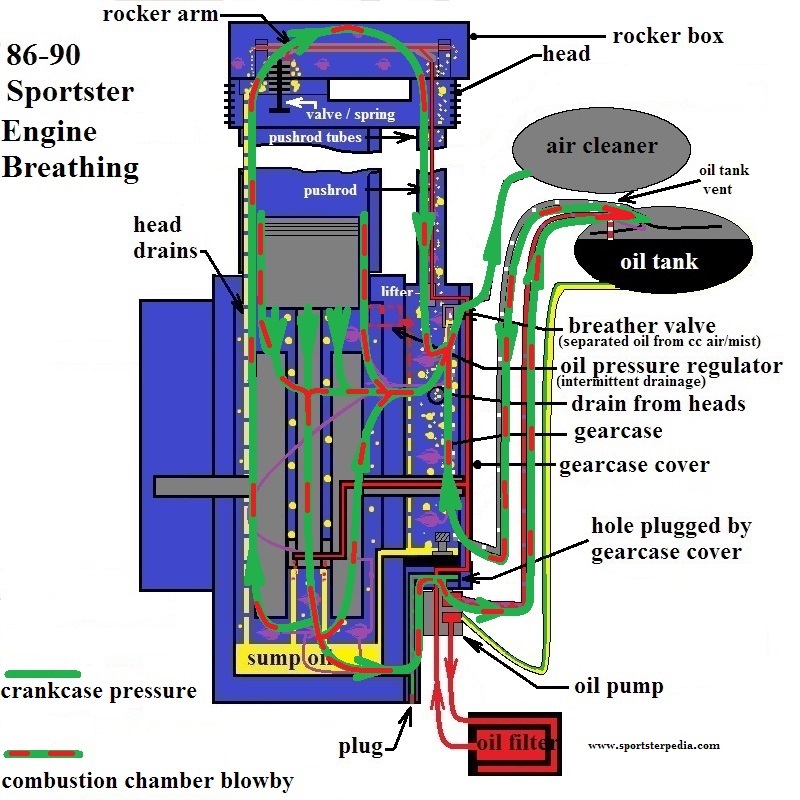
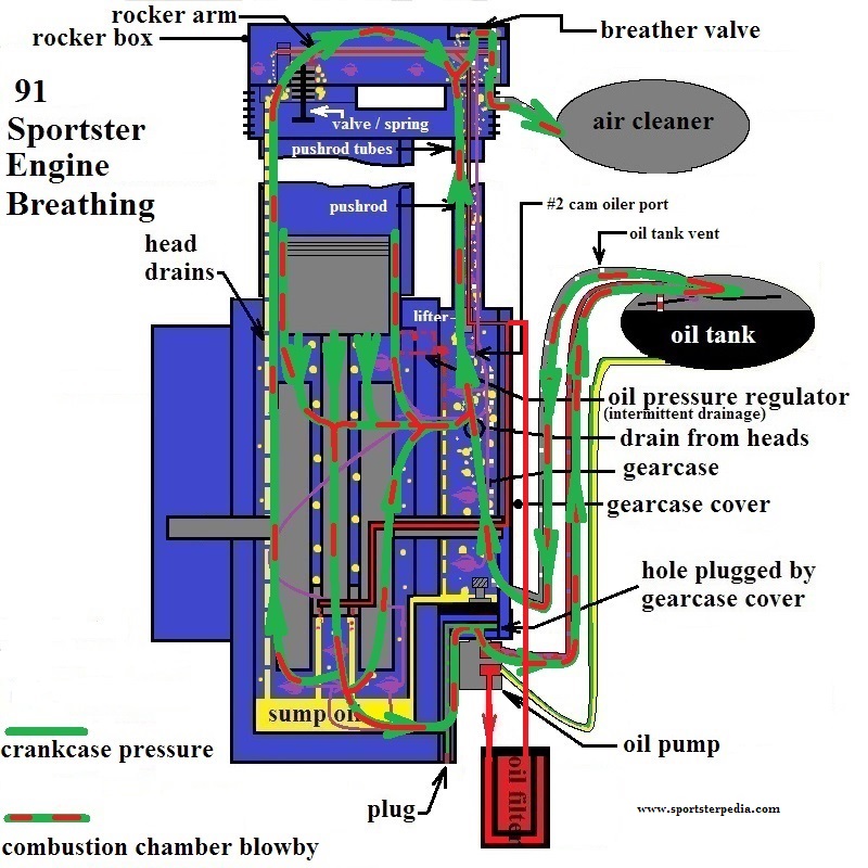
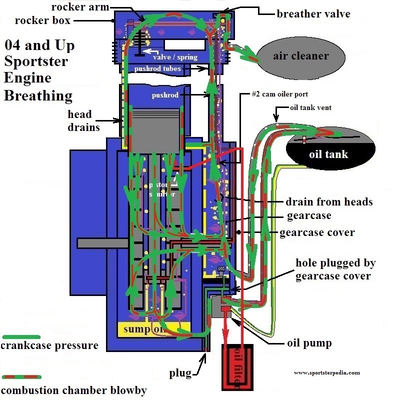
Engine Breathing
Engine ventilation is connected to the rockerbox, crankcase, cam gear case and the oil tank. 9)
If you blow down the oil tank line…air comes out the rockerbox vents (or cam breather hose).
There are airways linking these compartments together and in looking at these airways.
If one pressurizes, they all pressurize and air can pass between them;
- Rocker Box:
- Pushrods connect the rockerbox to the gearcase.
- Gravity oil:
- 03 and prior: Heads drain oil to the crankcase sump (through passages in the cylinders).
- 04 and Up: Heads drain oil to the gearcase (through passages in the cylinders and gearcase wall).
- All: Pushrod tubes drain oil into the gearcase.
- Gearcase / cam chest:
- Rockerbox oil return connects to the gearcase.
- Airways thru the wall joins the sump and the scavenge side of pump.
- Piston downforce pumps air and oil from the sump to the gearcase compartment.
- This would equalise air pressures in the two chambers.
- Crankcase:
- Piston downstroke creates a positive pressure against the oil in the sump.
- This forward pressure is connected to the oil tank thru the oil pump.
- It also helps to push oil into the scavenge chamber from the sump upward into the scavenger side of the oil pump.
- Piston upstroke creates a negative pressure (noted as vacuum for this article).
- Some of the oil either draining to the sump or collected from the sump is picked up by the vacuum in the form of oil mist.
- Also some of the oil is picked up in the form of oil droplets (or splash oil) and is moved around by the next positive pressure condition.
Splash oil is further moved by the action of the flywheels, connecting rods, cam gears, air pressure and gravity.
- The pinion gear shaft is hollow and connects the crankcase to the gearcase (but would only pass air with the engine off).
- 03 and prior engines connect rockerbox oil to the crankcase.
04 and up do not.
- Oil Pump:
- The pressure side of the oil pump is fed from the oil tank and is connected to the rocker box and the crankpin.
- Gravity from the oil tank initially feeds the oil pump.
- But once the engine starts, the motion of the gerotors creates a suction in the feed line from the tank.
- Pressure in the oil tank also adds pressure on the gravity feed to the pump.
- The pump creates non pressurized oil flow from the feed gerotors.
- Restrictions (oil line / feed passage sizes) to the oil filter pad and through the engine create back pressure on the pump.
- This pressure builds and is sent to the lifters and rocker box as well as the crankpin through the hollow pinion shaft.
- The pressure is increased at the pump as oil flows through more restrictions to get to these places.
(strictly as a non tested example, 10 psi on the feed side of the pump may equate to 4 psi or lower once it reaches the crankpin)
Pressure is restricted in the cam cover,
Less restricted with the wider opening at the pinion shaft bushing,
Then restricted again thru the shaft hole and the turns in the flywheel to the crankpin.
- Once the pressurized oil reaches the rocker arms and crankpin, the pressure is released into the wider openings in the oil path.
From there it is added to and becomes a part of crankcase pressure and is used and vented as such.
OEM oil paths and engine breathing drawings:

| Testing CC pressure on the dyno. 14) |
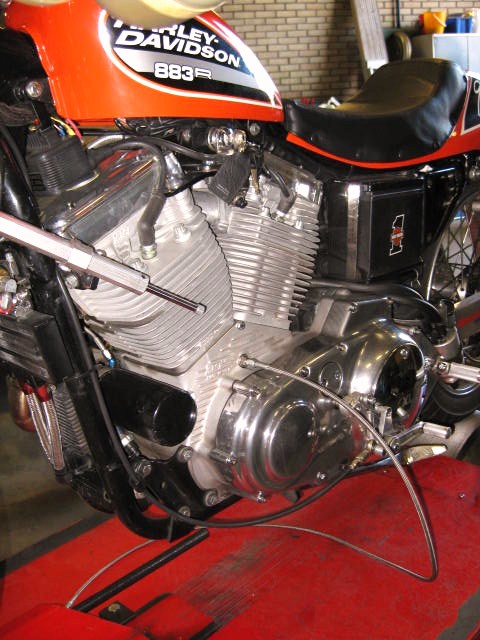 |
Revised crankcase breathing is an area where you have huge potential to create unintended consequences.
Few if any really understand the ifs, ands and buts of all the factors the factory took into consideration when they designed the system.
Gappless rings while great for ring seal are another area where you can get in over your head if you are not careful. 15)
Wet sumping is only one potential problem you may encounter with them. 16)
In the right application they can not be beat but you better have your ducks in a row.