Table of Contents

REF: Engine Mechanicals - Sub-05K
Installing "Slobber Stoppers" (1991-1993 Models)
The foregoing is a simplified version of engine breathing as it pertains to this mod.
This is a product of the engine breathing design where air/oil mist is sent into the rocker box and separated in a chamber between the middle rocker box and cover.
There is a rubber “umbrella” valve in each middle rocker box on each intake valve side.
With each downstroke, the air in the crankcase is forced past the umbrella valve carrying air/oil mist with it.
The umbrella valve sits in a confined separation chamber with a lowered “drain pool” beside it.
The umbrella valve is what keeps crankcase air inhalation/exhalation to a minimum.
The drain pool has an “exit hole” through it.
The oil is supposed to settle out in this little drain chamber and drain back to the motor thru the tiny hole in the cavity.
Crankcase air/oil mist rises up in each rocker box, hits the umbrella thus separating the oil from the air at that point.
By design, collision is the recipe for separating the oil mist from the air and the umbrella valves are the last collision point in the system.
Most of the oil falls off the bottom of the umbrella back into the lower rocker box section where it falls back down into the engine.
The residual air pressure runs past the umbrella, out a hole in each middle rocker section to a hollow bolt in each head (breather vents).
The “drain pool” in the separation chamber is suppose to collect oil spits that make it past the umbrella and route it back into the engine.
The problem arises when all of the oil doesn't separate at the umbrella, gets past the umbrella and the drain pool, and is blown out the breather vents.
Why it gets past these designed restrictions and the drain can get very complicated sometimes.
Obviously, a larger than normal quantity of oil gets past the separation chamber and left into suspension to move out the motor with the air.
It's normally still in the air/oil mist state unless there is another problem that needs to be diagnosed.
The rubber umbrellas will harden over time and not close down like they should so they need to be inspected periodically and replaced if they are hard.
That alone should improve the condition some.
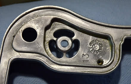
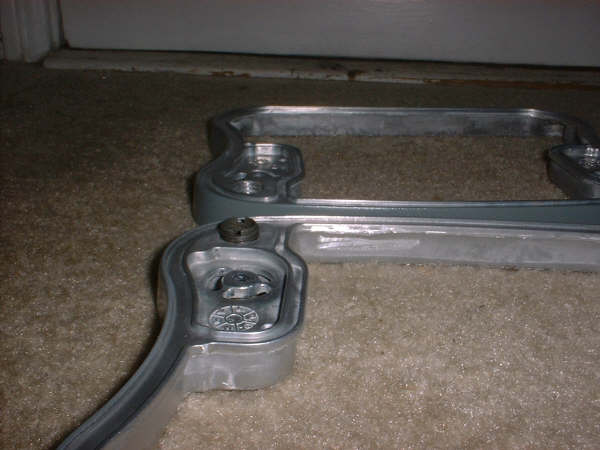
The umbrella valve hole is the one in the left picture below with 3 roughly oval shaped holes around the install hole in the corners of the middle rocker box. 1)
(2 umbrella holes per middle box spacer, only 1 is used per cylinder on the each intake side as the box spacer is interchangeable front to rear)
The 3 oval shaped holes are where air/oil mist enters the separation chamber while lifting the umbrella up.
The drain back hole is the tiny little hole to the right of the sideways 13 in the picture.
Oil is also pulled down that tiny hole by vacuum on each upstroke.
 2)
2)  3)
3)
The Slobber Stoppers are an attempt to (possibly help) curtail the issue of puking oil out the breathers. 4)
However, the first answer would be to address other known factors for wet sumping.
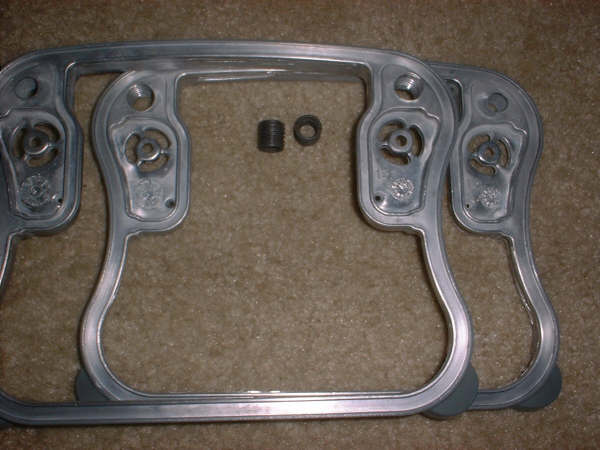
The rocker box middles use the same casting for both the front and rear cylinder. And there's a facility for the umbrella valve on both ends of each middle spacer.
So you can try this, and if it doesn't work, just move the umbrella valve to the other end.
And use the rocker box middle on the other cylinder. In other words, this mod is undo-able… once anyway.
Parts
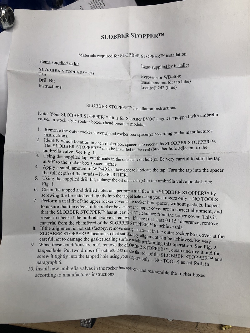
- The kit comes with:
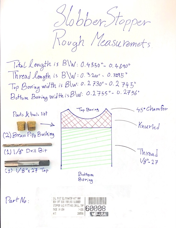
- (2) brass barrels with 1/8“-27 threads on one end (looks like a pipe bushing that was knurled and slotted on the end).
- (1) 1/8”x27 tap.
- (1) 1/8“ drill bit to enlarge the drainback hole in the drain pool.
- Instructions
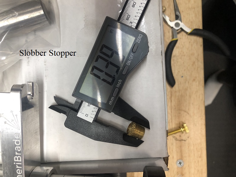
The measurements in the drawing below should considered (rough dims) as neither of the barrels included in that kit were identical. 5)
(click on a pic to enlarge):
 6)
6)

Below are app. dims of one of the barrels in this kit taken by XLForum member, salmanmr.
Note: The barrels in this kit were not identical.
 11)
11)  12)
12)
Installation
Tapping the Holes for the Barrels
The threads need to be cut on the same side as the umbrella will be installed (intake side of each middle box).
If you'll go ahead and remove the umbrella before tapping, you don't have to be so particular with what solvent or cleaning solution to use to clean the shavings up.
Run the tap in the hole at 90° and keep it straight while cutting the threads.
Lube the tap with a liberal amount of cutting oil (instructions say WD-40 or kerosene but neither are suitable cutting oils).
The threads should be cut without any jagged edges on the them that could eventual cause an air leak.
Decent cutting oils will allow for better final threads.
As with any home tapping operation, don't try and tap the hole all at once.
Run the tap in about a half a turn, back it out, run it in for another half turn, back it out etc.
Each time backing it out, clean the tap (WD-40 works good for that) and re-lube it.
Continue cutting just to the depth of the threads on the barrel (no more).
The barrel's height needs to be as tall as possible without interfering with the cover and still allow enough space for air to move out through the barrel's center.
When done, clean all shavings from the middle rocker box.
Then test fit the barrels and measure the clearance between each barrel and cover as in below.
Measure the Barrel to Cover Clearance
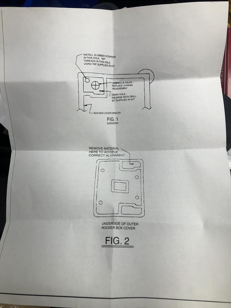
The instructions say to insure that the rocker cover has at least .015” clearance from the barrel fitting and the inside (bottom side) of the cover with the gasket removed.
Procedure is, turn the cover upside down. Thread the barrel in the newly tapped hole in the middle box (hand tight).
The place the middle spacer on the cover as it would normally sit when installed on the motor (leave the gasket out).
Now measure the clearance between the barrel top and the underside of the cover.
When you add the gasket upon install, the clearance will increase (more space depending the thickness of the compressed gasket).
A used James rocker box gasket was recently measured at .095“ (uninstalled). 15)
With the spec being without a gasket, the added thickness of the installed gasket should yield enough space for air to move out the breather vents as intended.
If the clearance is less than .015”, the instructions say to take a little off the top of the barrel to get that clearance needed.
The used .095“ gasket above and the .015” measured clearance means the target installed clearance is in the neighborhood of .111“ total.
However, this is not an easy task. Normally you'd remove the umbrella and snake a feeler gauge into one of the slots at the umbrella hole.
But a standard blade type .015” feeler gauge will not bend enough to run thru one of the slotted holes to the area to be measured.
So to find that clearance, you could stuff some clay in the cavity in cover, put the pieces together then remove and measure the depth of the clay.
You can't measure between the cover and middle section since the barrel should not be tall enough to raise the cover even if the clearance was too little.
Another problem measuring the clearance is that the surface of the cover where you need to measure is not flat.
It's sitting at an angle and the barrel is vertical.
Down and dirty way to get the clearance dimension:
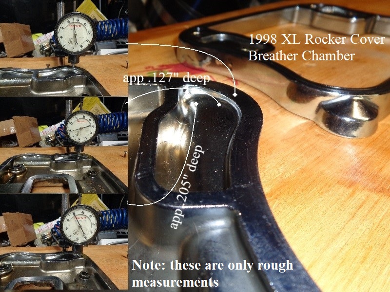
Below are (dirty) dims on a 1998 XL rocker box cover. The depth of the breather chamber starts at app 1/8“ an the end of the angled shelf is just below 13/64”
So the factory clearance above the breather exit hole may be app .015“.
(which really doesn't matter as much since the whole cavity is free flowing to the exit hole with the OEM setup).
But for the purpose of adhering to the specs for this mod;
The barrel for this particular setup can't stick up more than an 1/8” above the middle spacer without contact to the cover (.002“ clearance without gasket).
So if you install the barrel to a height of 1/8”, you'd need to cut/grind .013“ off the top of the barrel without needing to grind the cover.
(in order to gain (.015” spec) clearance required and keep the top of the barrel vertical)
Or, you could cut the top of the barrel at the same angle as is the inside of the cover to gain some clearance.
The angle in the cover is superimposed, angles front to back and side to side so it's difficult to measure.
Just pick the tallest area you think that might touch the cover to take your measurement.
(another way to keep from having to grind the cover)
 16)
16)
Clearancing the Barrel(s) (if needed)
It's best to remove the barrel, place it in a bench vise gently (soft jaws help keep from hurting the barrel) and grind a little off the top.
You can generate a lot of heat when grinding that may distort the newly cut threads.
You can use a file for light cutting if you can hold the barrel straight without squishing it (as in a vise).
Or you can use a grinder or Dremil tool with a metal cutting blade to take a little off the top of the barrel.
“Measure twice / cut once” so you don't take too much off the barrel though.
Clean the barrel of all debris and do the test fit again. Make sure the .015“ clearance is there now. Repeat if needed.
Clearancing the Cover (if needed)
It's best to try several ways to clearance the barrels instead of the covers if possible.
In the area that the barrel sits, the cover is only around 1/8” thick.
So grinding on the cover will reduce that thickness and may create a crack in that area from vibration with the engine running.
If you have to, use caution with a die grinder or rotary tool with a grinder bit.
In fact if you achieve the clearance on the barrel, then install the boxes (with gaskets), that raises the cover with even more clearance from the barrels.
So the only plausible reason for the instructions reading (remove material from cover) would be to get the pieces straight to take the barrel clearance dim.
And that's due to the angled shelf in the cover.
You shouldn't need to grind into the cover for that. See “Measure the Barrel to Cover Clearance” above for a better way to get that clearance dim.
Drilling the Drainback Hole
The kit comes with an 1/8“ drill bit to enlarge the drainback hole in the drain pool chamber. But be aware that;
Each motor has different conditions and what works for one may not for another.
Drilling that drain hole may allow more crankcase air/oil mist to escape the engine on downstroke when it's supposed to escape thru the umbrella.
When the umbrella closes (upstroke), the only intake of air is that tiny drain hole.
And IF there is not enough oil in that cavity to drain back, it may allow too much atmosphere to come back into the motor.
Added air intake may promote wet sumping. So make sure not to wobble the hole any larger than the bit.
It may be a trial and error thing and if you do one mod at a time, you'll know more about what worked and what didn't.
The engine is designed to have a slight vacuum in the breathing system on the inside of the motor.
On upstroke, the vacuum pulls oil down to the boxes thru that drain hole. It's too small for gravity to flow oil.
Enlarging the hole, especially too much, will allow vacuum to drain the oil faster, which gives more time to suck in air before piston direction changes again.
You could first try and chamfer the umbrella hole to 60º (included angle) countersink bit and not drill out the drainback hole. 17)
However, to the extent the drain back hole is enlarged, it bypasses the umbrella valve back into the boxes. 18)
Maybe 1/8” isn't enough to cause an issue according to the makers of Slobber Stoppers.
But inhalation/exhalation is what carries oil out the breathers so you don't want to bypass it any more than necessary.
You could probably do the chamfer, but not the drain hole enlargement. Then, if you still have the issue, you could also drill out the drain hole.
And with this mod being undo-able by swapping the front and rear middles, you have a safety net in case something goes wrong.
Another suggestion is to enlarge the tiny oil drain from ~.070“ to .09375” along with the threaded insert oil standoffs. 19) 20)
Slightly enlarging the little hole lets the oil drain back easier. Air that enters this oval(ish) chamber has to go somewhere.
So it goes out the big hole on top, thru the breather bolts and out. The threaded insert just provides a lip around the hole.
So any oil that drops out of suspension around the air hole won't drain out the breather. It just makes it a little bit harder for oil to go out the breather.
Install the Rocker Boxes
Before installing the rocker boxes back on the motor, make sure they are clean from all dirt, debris, shavings etc.
It won't hurt to spray them down with carb cleaner etc. before installing the umbrellas. The instructions say to install new umbrellas anyway.
Make sure both the umbrellas and their now counterpart Slobber Stoppers goes on the intake side on each cylinder.
Visually inspect that either gasket does not pinch or pooch out after you tighten up the cover bolts.
If so, loosen or remove the cover and tighten them again or it'll leak oil.
Cover bolt torque is 10-13 in-lbs (FSM says ft-lbs but this is wrong).
OEM cover bolts have a washer pressed onto the bolt with a corresponding fiber washer added for each bolt.
Some aftermarket kits have the fiber washers and copper washers. Use either / or but not both types of washers together.
If reusing fiber washers, (not recommended), check them to make sure the fiber hasn't already began imploding. If so, do not use the offending washers.
Vacuum from the rocker box area will eventually implode the fiber washers (looks like an O-ring around the threads and the washer OD is smaller than new ones).
If there are any air leaks around the cover bolts, even with the Slobber Stoppers added, you may still get oil out the breather vent(s).