Table of Contents
REF: Oiling & Lubrication
Sportster Oil Feed Chain Pressures and Dynamics
Fluid dynamics is “the branch of applied science that is concerned with the movement of liquids and gases,” according to the American Heritage Dictionary. 1) Fluid dynamics is one of two branches of fluid mechanics, which is the study of fluids and how forces affect them. (The other branch is fluid statics, which deals with fluids at rest.) The study of liquid flow is called hydrodynamics. While liquids include all sorts of substances, this article is genrally considering oil flow.
The following subjects below are not generally discussed in detail but rather as an overview. You can do a search online or otherwise for greater in depth studies.
Credits to this article and their links are given at the bottom of this page for further reading as well.
Oil Tank Head Pressure
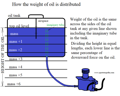
The Hydrostatic Pressure of a fluid at a given depth does not depend upon the total mass or total volume of the liquid. 2)
Because of ease of visualizing a column height of a known liquid, it's become common practice to state all kinds of pressures in column height units.
Pressures are often measured by manometers in terms of a liquid column height.
The pressure exerted by a static fluid depends only upon the depth of the fluid, the density of the fluid, and the acceleration of gravity. 3)
The pressure in a static fluid arises from the weight of the fluid and is given by the expression: P = pgh.
P = static fluid pressure
ρ = fluid density
g = acceleration of gravity
h = height of fluid
Example:
Relative Density (same as specific gravity) of Mobile 1 V-twin 20w50 is (.87) at 60°F (15.6°C).
Specific Gravity of water is (1.0) at 60°F (15.6°C).
For the example below, we'll use these figures:
Relative Density: (.87)
Standard Gravity: (32.174 ft/s²) - feet per second squared
Height: (1.23ft) - as eyeballed on a 1998 1200S, 14.75“
Example calculations: P = pgh
P = .87 x 32.174 ft/s² x 1.23 ft = 34.43 ft/s² (rounded figures)
Converting ft/s² to in/s² : 1 psf = 0.00694 psi (34.43 x 0.00694 ) = 0.239 psi (rounded figures)
So by these figures, the oil tank head as seen at the oil pump inlet is 0.24 PSI on a 1998 XL1200S (static pressure, not flow pressure).
This is assuming the oil level is at 60°F and at the top mark on the dipstick.
Oil density lowers (gets lighter) when heated. So the .87 figure above may go down to around to .82 at 212°F (100ºC).
In that case, the static pressure would go down to around .225 PSI at operating temp.
Lowering the oil level to the low mark on the dipstick will lower the pressure at the oil pump slightly.
But it is not gravity that actually pulls oil into the pump. It's vacuum created by the gears / gerotors that does most of the oil gathering.
A change in location elevation from sea level can also change the pressure at the oil pump.
The mark is there as a minimum oil level to attain enough pressure at the pump to keep down cavitation in the oil pump.
Below are some examples of things that could lead to pump cavitation;
- The roughness of the feed hose ID can lower pressure at the pump due to the affects of friction.
- Kinks in the feed hose or internal shrinkage of the inside walls of the feed hose can lower pressure at the oil pump.
- Changing the inlet fitting to a smaller ID can lower pressure on the hose side of the fitting.
The static pressure at the inlet is changed further upon vacuum from the oil pump inlet.
The hose fitting is a restriction where flow (from vacuum)of pump gear action lowers static on the hose pressure.
Specific Gravity
Specific gravity is the heaviness of a substance compared to that of water, and it is expressed without units because
it is simply a ratio. 5)
In the metric system, specific gravity is the same as in the English system.
If something is 7.85 times as heavy as an equal volume of water (such as iron is) its specific gravity is 7.85.
Its density is 7.85 grams per cubic centimeter, or 7.85 kilograms per liter, or 7.85 metric tons per cubic meter.
In relationship to liquids, the term specific gravity is used to describe the weight or density of a liquid compared to an equal volume of fresh water at 4°C (39° F).
Specific Gravity of water at 4°C (39° F) has been assigned a value of one (1).
If the liquid you are comparing will float on water it has a specific gravity of less than one (1).
If it sinks into the water, the specific gravity is more than one.
There is no correlation between viscosity and specific gravity.
Specific gravity can be measured with a hydrometer.
It consists of a glass cylinder with a rubber bulb on top, and a float positioned inside the glass tube.
The float is calibrated to float on fresh water.
If the fluid you are testing has a higher specific gravity, the float will raise in the liquid.
And at a lower specific gravity it will sink lower in the liquid.
This is the same type instrument used to tell if an automobile battery is fully charged.
Or another version of this instrument tells the concentration of anti-freeze in an automobile radiator.
You can observe the little balls floating in the tube.
Standard Gravity
According to Wikipedia, standard gravity is the nominal gravitation acceleration of an object in a vacuum near the surface of the Earth. 6)
Standard Gravity was established at the third General Conference on Weights and Measures in 1901.
The standard gravity on Earth is 9.80665 m/s² (meters per second squared), or 32.174 ft/s² (feet per second squared).
However, standard gravity only applies to an object or body at sea level and geodetic latitude of 45 degrees.
This figure will change somewhat depending on the elevation above sea level where you are.
So, for more accurate result, calculating your own local gravity would be better.
Oil Pump
A Sportster oil pump is a positive displacement pump with a fixed displacement.
It is non-regulated and delivers its entire volume of fluid under pressure to the (motor 1957-1985) or (oil filter, then motor, 1986-Present).
Both of these type pumps are in the “rotary pump” category.
1957-1976 Gear Pumps: These make use of two tight-meshed gears within a housing. One is the driving, or powered, gear, while the other is driven, or free-flowing. The fluid is trapped in the space in between the gears and rotated through the housing. Since it cannot move backward, it is forced through the outlet pump. 7)
1977-Present Gerotor (generated rotor) Pumps:
The internal gear design places an inner gear inside of an outer gear. The fluid is moved via eccentricity — the deviation of the gear from circularity — between the gears. The inner gear, with fewer teeth, turns the outer gear, and fluid is drawn in, moved through the gears, sealed up and discharged. 8)
Measurable oil pump (static) pressure is a result of engine restrictions on the pressure side of the pump.
The initial restriction area from the pump establishes “System Pressure” that can be measured with a static PSI gauge.
However, the pump has a variable flow rate (due to the variable engine speeds that turn the pump).
The same amount of oil comes out of the pump on every gerotor revolution.
But since the pump is not regulated, the amount of crankshaft revolutions determine the amount of flow the engine receives.
More RPM sends more oil to the motor and less RPM sends less oil to the motor. Oil pump speed is 1/2 of engine speed (except 1/4 speed XRs).
If the engine idles at 1000 RPM, the oil pump is turning at 500 RPM. And in reverse, the crankshaft is turning twice the speed of the oil pump.
For each revolution of the pump, a certain quantity of fluid is enclosed and transported from the pump intake to the pump outlet irrespective of counter-pressure (back pressure from upstream restrictions). 9) That is, the amount of oil delivered from the pump does not change even though the different pressure heads do change downstream. The enclosed volume of fluid delivered per revolution depends entirely on the size of the displacement cavities in the pump (hence the name displacement pump). The maximum attainable pressure head increase is primarily dependent only on the mechanical strength of the pump assembly and the driving power available (engine RPM). The pressure head increase can be limited by means of a maximum pressure valve (relief valve, safety valve) installed in the system or integrated in the pump. Most positive displacement pump manufacturers advise to have a pressure regulator installed near the pump since it is not regulated. More RPM brings more oil delivery and thus more system pressure buildup.
Does the Oil Pump Make Pressure or Not?
There are several types of pressure at work at the same time in the oil feed chain. The oil pump creates a flow of oil (flow pressure) that is sent through a set of clearances within the motor. The resistance to that flow of oil through those clearances is what creates static oil pressure. But without the pump working, there would be no pressure. So in reality, the oil pump creates pressure by default. Most people say (including manufacturers and engineers) that positive displacement pumps create flow but not pressure. The pump manufacturers do not know the piping system or friction losses in the intended application. So they are saying the pump itself doesn't create system pressure (for those who are sizing what pump to use).
However, if you remove the feed output hose from a Sportster and fire up the motor, oil shoots out onto the floor from the pump due to the flow pressure the pump's gears are creating when they squeeze together. You can't use the pressure that way unless you are spraying oil on an ant bed. At that point, pressure is released the moment it comes out of the pump outlet. That is not to say the flow pressure goes away there. When you plug the pump back into the motor, flow pressure will be harnessed by system plumbing, which gives rise to static pressure while flow happens in the beginning feed piping and morph as it is sent elsewhere in the system.
Flow pressure (or dynamic pressure) is how fast the oil is moving, or being moved. This is usually not thought of much. What we think of as “flow” does have a force (pressure) pushing it. It is measured in the center of the stream (only) and right at the outlet (in psi) typically with a pitot gauge. The tool does not stop flow for a measurement. You just insert it into the flow. It looks like a long tube smashed on the end with an orifice pointing directly into the stream.
Ever used a water pressure sprayer at a long distance (car wash)?
Ever noticed the closer you get to a dirt spot, the easier it is to remove the spot?
The flow pressure is strongest right at the outlet (when flowing to atmosphere).
Just like flow pressure is greatest at the oil pump with the hose off.
Flow pressure will dissipate into atmosphere as the flow gets farther away from the pump.
But right at the outlet, there is flow pressure.
Pump manufacturers / others say pressure is at atmosphere without restriction on the end of the pump.
This is not true directly at the outlet but is true the farther away from the outlet fluid gets.
You can test this by covering the outlet with your finger.
Flow pressure will burst out around your finger.
The farther away you are from the outlet (spray nozzle), the lighter the pressure is.
If you hold a pressure washer spray nozzle right next to your finger, the spray will cut into the skin.
What we think of as “pressure” is actually static pressure. It is measured with a standard PSI gauge.
And this is the pressure “others” say is not present at the pump. And they are right in that.
Trouble is, they don't mention “flow pressure” which apparently leads readers not to account for it.
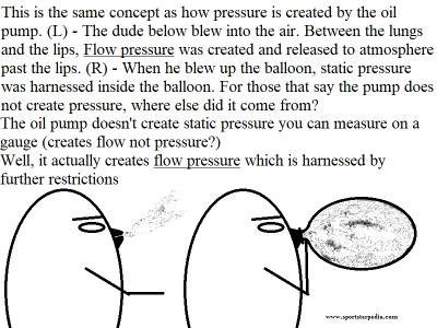
The drawing below examples how flow pressure is harnessed while blowing up a balloon. When blowing into the air, first, flow pressure is created by the lungs to the lips. Then that same flow pressure, created by the lungs, is released to atmosphere and the residual air pressure (static) past the lips is zero more than atmosphere. However, when the person blows into a balloon, the flow pressure is collected into the balloon. As more air is pushed into the balloon, the sides stretch and the balloon gets wider as it harnesses incoming flow pressure. The result is stored (static) pressure inside the balloon which could be measured with a standard pressure gauge. If you were to cut a small hole an the rear of the balloon and stick a straw in the hole (if it would bust the balloon), some of the static pressure would flow out as flow pressure. What pressure stays in the balloon while the straw is passing air is the static pressure.
The oil pump and pressure works the same way. Flow of any sort will not happen with a pressure differential somewhere.
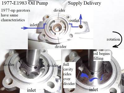
Oil is forced from the gerotor teeth on the discharge side down into a cavity that gets pressurized by more incoming flow.
Then oil expands by way of pressure to the outlet port of the pump. Flow pressure is created and morphs as it is sent through the system.
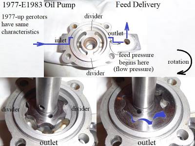
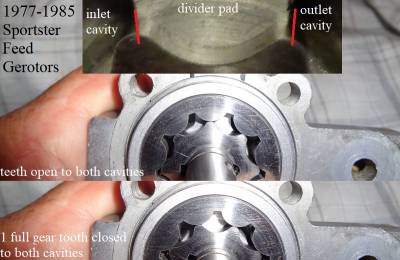
The pump below is for 1977-E1983 Sportsters but the oil pickup and discharge concept is the same for 1977-present Sportsters.
Oil Pump Suction
With gravity oil only being less than 1/4 psi, that may or may not work at idle.
But on high RPM, gravity may not be enough to supply enough oil to keep from cavitating the pump without suction.
Suction is a byproduct of the spinning gears. It's gonna happen whether wanted or not.
But it is also used to help bring oil into the pump inlet cavity.
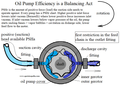
The hose fitting is a restriction and according to Bernoulli's principle, suction is higher in the cavity than in the hose.
The higher suction on higher RPM in the inlet cavity lowers static in the hose even more.
Positive displacement pumps generate a certain amount of suction through spinning action by default and are capable of creating “suction lift”.
How much suction lift is based off the capability of the pump design. Big pump gears, big suction, smaller pump gears, smaller suction.
The suction (vacuum) is the highest at the gear mesh areas. Suction is created by the rotating gears / gerotors.
However, enough suction is not possible without a hydraulic (oil) seal within the clearances.
Positive displacement pumps generate a certain amount of suction through spinning action by default and are capable of creating “suction lift”.
How much suction lift is based off the capability of the pump design. Big pump gears, big suction, smaller pump gears, smaller suction.
The suction (vacuum) is the highest at the gear mesh areas.
Suction is created by the rotating gears / gerotors. However, suction is not possible without a hydraulic (oil) seal within the clearances.
Oil pump prime and suction lift:
An amount of oil in the clearances allows the gears to pull oil under vacuum from the suction cavity into gear mesh.
Having oil in the pump to create the hydro seal is called “primed” in the FSMs.
The Sportster oil pump is capable of priming itself due to the oil tank being higher mounted than the oil pump and the tight clearances.
The FSMs say that if you have removed / replaced the oil lines, you should prime the pump (add oil to the pump) before installing.
As long as there is oil in the clearances, the pump will immediately create suction on startup (some use assembly lube instead of oil to prime the pump).
Most positive displacement pumps are also capable of a certain amount of suction lift on the inlet hose even if not primed.
But that would also mean there may be several seconds of running the oil pump dry that may involve damage to the pump internals.
It could also cause cavitation with no oil in the pump and trapped air in the feed hose.
The harder the pump vacuum, the more oil flow that needs to come from the tank. Else, the pump starts sucking fumes off the oil.
This is the definition of cavitation.
Sportster oil pumps are considered to have a “flooded” inlet (tank is mounted higher than the oil pump).
This helps reduce the amount of vacuum needed from the pump as gravity will help push the oil into the inlet.
The OEM oil supply hose from the tank (feed hose) is 3/8” ID.
Changing supply hose size and/or the inlet fitting ID will alter the amount of flow to the pump.
It is not recommended unless you can test the results afterwards and deem the change to be helpful to the oiling system.
Clearwater Hydraulics' recommended velocities thru the hoses are; 14)
Suction lines (hose between the reservoir and pump) should not exceed 4 feet per second.
Pressure and Return (any pressure or return hoses) should not exceed 15 feet per second.
Suction generated on the supply hose is increased using a smaller hose but that limits reserve oil (A)vailable in the hose, with possibility of cavitation.
Suction generated on the supply hose is decreased by using a larger hose and even more by using a larger ID inlet fitting.
But that may reduce suction too much and decrease pump efficiency on high RPM.
Oil pump feed cavity layout:
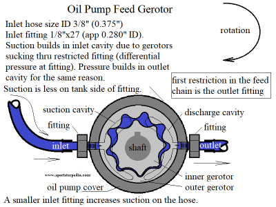 15)
15)
Return Vacuum from Sump to Pump
Vacuum is created in the return side of the pump just as it is in the feed side of the pump.
As long as the oil in the crankcase is positioned at the hole to the return passage for the oil pump, pump vacuum will extract the oil.
However, since the feed gears / gerotors are smaller than the return gears / gerotors, air will also be picked up by the pump returned to the oil tank.
The vacuum is built in the feed and return cavities in the pump housing by the opening of the gear teeth.
So the amount of total vacuum created starts at the gears.
The cavities next to the gears are basically chambers where gear opening pressure differential is manipulated whether strongly or not depends on cavity size.
In the testing below;
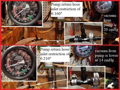
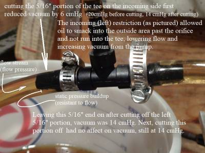
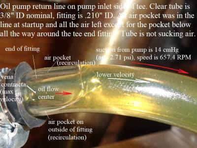
A plastic universal tee was added to the return hose bench testing a 1991-1997 Sportster oil pump.
The 5/16“ nubs were left on the tee with 3/8” hose slipped over them to the 3/8“ nubs.
The tested vacuum was at 20 cmHg with the 5/16” nubs (app 0.160 ID) and 14 cmHg with just the 3/8“ hose nubs (0.210” ID).
The vacuum lowered with the bigger ID tee.
| Video of no vacuum pressure w/ no oil in hose 18) |
Oil Pump Internal Oil Leakage
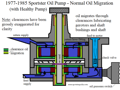
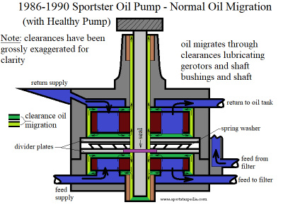
Normal Oil Migration
A certain amount of internal oil migration is always present in displacement pumps, this is due to the clearances between the moving parts.
A Static System Pressure reading (standard pressure gauge) will be including this amount of migrating oil.
In addition, wear between the working parts will increase the amount of oil migration.
A small amount of oil (oil film) rides between the top and bottom of the gearset on gerotor pumps at their respective riding surfaces in the pump.
Due to the rotating gears and gearshaft, oil is pulled through the clearances.
This is normal and the clearances are there to cut down on heat buildup and galling.
Below is a drawing of a 1986-1990 Sportster Oil Pump.
The clearances have been drawn wider than they actually are to show their existence and general direction of flow.
System Pressure Loss From Internal Leakage (recirculating oil)
Some amount of wear in the oil pump is expected as time goes by.
Metal to metal contact, and wear thereof, is a part of reality. All mechanical parts break down or fail in some way over time.
Oil will carry metal grit and bigger chunks to every part of the feed oil path. Sometimes grit and/or bits of metal are dragged through the oil pump.
Sometimes, this debris will have an adverse affect on the gerotors / gear. However, most damage from debris first is noticed in the oil pump housing itself.
You may find scratches on the surface where the gears / gerotors ride.
You also may find gouges in the sides of the housing where gear teeth spin.
You may also find gouges / blemishes / heat spots in the housing between it and the outer gerotors.
You may find pits in the aluminum cavities on the outlet cavities in the oil pump (can be caused by debris or cavitation).
Any of these can easily carry more oil (recirculate) from the outlet cavity back to the inlet cavity of the oil pump.
This will reduce the amount of oil delivered to the engine to some degree.
Recirculating oil in the oil pump will also result in higher heat to the oil before it gets pumped out of the oil pump.
The amount of leakage, which reduces the amount of flow to the motor, varies according to the amount of pump wear, viscosity of the oil and RPM.
Internal leakage can cause higher heat to the oil as well.
However, the efficiency of positive displacement pumps increases as the pressure increases.
At low RPM, the percentage of slip in relation to volumetric displacement is higher than at high speed. 21)
Affects of Viscosity
As mentioned above, there is always a certain amount of internal leakage in a pump that is within clearance range.
The normal oil film is oil that is removed from the feed oil cavities to redistribute and cool the moving parts in the oil pump.
Regardless, this is a very small portion of the total feed oil available to the engine.
But it does amount to a recirculation of feed oil before being pumped out.
The amount of feed oil removed for pump cooling is increased with wear (that affects the clearances).
Bigger clearances equal more oil removed (or recirculated) from the feed outlet cavity back to the inlet cavity.
The amount of internal oil leakage will be less when the oil is colder (thicker) on startup.
Thicker oil can help to seal the clearances and reduce internal leakage.
The amount of internal oil leakage will be greater when the oil is hot (thinner) at operating temp.
Thinner oil has more potential to get by the clearances.
If you haven't changed the oil for a long time and oil viscosity is broken down further, the amount of internal leakage increases.
If oil gets heated up enough to lower it's viscosity even more, the potential for internal leakage increases.
If you have gas mixed with your oil, viscosity is lower and the potential for internal leakage increases.
If you have worn clearances in the oil pump, the potential for internal leakage increases.
Teeth Clearance
1977-Up Gerotor Oil Pump:
There is a clearance between the inner and outer gerotors in order to counteract galling and to reduce friction within the pump.
Leakage occurs from the delivery side back to the suction side, (against the direction of flow).
Since flow pressure is actually established based on how much pressure is squeezed out between the inner and outer gerotor teeth;
If there is wear at the teeth (causing a greater clearance between the teeth mesh), actual pressure squeezed to the outlet cavity will be lower.
This will lower system pressure at the oil pump since some of the pressure from the outlet cavity will be carried back to the inlet cavity between the teeth.
Generally, worn teeth clearance is not as common as scratches on the divider pads between the cavities.
That is not to say teeth wear doesn't happen, as large chunks of metal have gotten caught between the teeth to damage them.
So teeth wear does happen, but housing wear is usually noticed first since the housing is aluminum and the teeth are hardened steel.
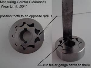
The FSMs give a gerotor teeth clearance to be checked when the oil pump has been removed and disassembled.
The maximum clearance between an inner and outer gerotor is .004“ (0.1016mm).
So the working clearance range is whatever design dims were up to .004” of total clearance.
The clearance is checked with a feeler gauge as shown.
Thermal expansion of the casing and gears reduces clearances within a pump during operation. 22)
This can lead also lead to increased wear, and in extreme cases, pump failure from worn clearances.
As clearances increase, there is a gradual reduction in efficiency and increase in flow slippage.
Flow slip is proportional to the cube of the clearance between the teeth and casing.
So, in practice, wear has a small effect until a critical point is reached, from which performance degrades rapidly.
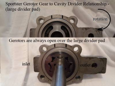
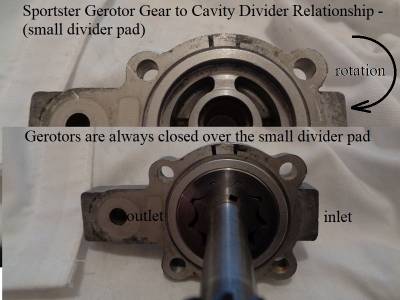
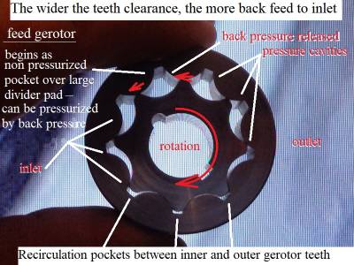
The gerotor teeth relationship does not change at any given point in rotation.
That is, teeth that are open over the large divider pad are always open at that point and teeth over the small divider pad are always closed there.
Same relationship over each inlet and outlet cavity respective of position of the teeth.
In the right pic below;
Notice that when the teeth are closing rotating over the small pad toward the inlet cavity, there is still a small gap between inner and outer teeth.
A small amount of oil is filling that gap and is being recirculated from the outlet cavity back to the inlet cavity.
The teeth do not touch and are clearance apart to keep down metal to metal wear. But the byproduct of that is the clearance allowing oil to recirculate.
Total clearance more than .004“ between the teeth (small pad) allows more oil to recirculate back to the inlet cavity (decreasing output flow).
Total clearance more than .004” between the teeth (large pad) brings more oil per revolution to the discharge cavity.
And in the process, decreases pressure in the outlet cavity (decreased system pressure) as it also carries more oil back to the inlet cavity.
Both pressure and release clearances would be wider and more oil would be squeezed toward the inlet cavity from each divider pad area.
Oil Migration on Gerotor Faces
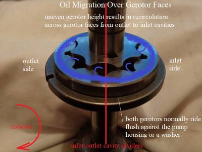
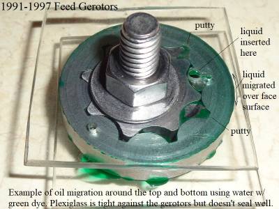
Oil migration over the gerotor faces is an inherent situation as both the top and bottom of each set rides on an oil film during operation.
While the oil films is necessary to ward off from metal to metal contact, oil does migrate through the very small built-in clearances.
With both gerotors in a set having the same height, the running clearance is established by that height.
Changes in gerotor height from wear increases the running clearance and the amount of oil migration.
Wear can shorten the height (either both inner and outer or one or the other).
If both gerotors wear down the same, they will still be shorter than designed which will increase the running clearance.
If an inner or outer gerotor wears more than it's matched counterpart, there will be a larger increase of clearance on top and bottom of the set.
This will result in more oil migrating across the face from outlet to inlet cavities and lower system pressure.
If this is the case, the gerotors are compromised and should be replaced with a new matched set.
Pump Housing / Cover
Gerotor Oil Pumps:
- Scratches on gerotor riding surfaces:
The surface in the housing or cover where the gerotors ride can get scratched from grit or debris traveling with the oil.
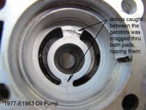
Debris caught between the teeth rotate across the dividers between the inlet and outlet cavities gouging the divider(s).
This has been noticed more on the larger divider pad although scratches do appear on both dividers (especially 1977-1990 oil pumps).
This has also been noted more on the return gerotors than the feed side.
Broken motor internals go thru the return side first, then the oil tank.
Heavier pieces fall below the feed outlet in the oil tank.
So for bits of motor internals to get to the feed side to score it up, they first had to travel to the retrun side, possibly scoring that up initially.
The feed gerotors are open across the large pad and it's easier to trap debris between the inner and outer teeth while dragging it across the pad.
Minor scratches can be from grit in the oil being dragged across the pads when gotten under the gerotors.
So there could be multiple scratches with multiple causes over time on the divider pads in the oil pump.
The gerotors are designed to ride against flat surfaces. Scratches in the riding surfaces can allow oil to recirculate (outlet to inlet).
This will lower the amount of flow that goes to the engine by however much oil can make it through the scratches.
This can also lower static pressure on the feed side especially on sustained idle or lower RPM if the scratches are deep enough.
1977-1990 Sportster oil pumps will have more of a tendency for deeper scratches in the cover than later oil pumps.
This is due to the two divider spacers (1 each on feed and return gerotor facing each other) with a spring washer between them.
The spring washer will allow the gerotors to jerk down or up on impact.
There is a space between the plates that separates feed and return gerotors held away from each other with the spring washer.
Debris caught between gerotor teeth can cause the gerotors to jump up/down allowing debris to get under them.
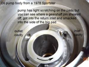
This allows larger debris to be dragged through both the large and small cavity divider plates leaving deeper scratches on pump cover.
How much pressure loss would depend on the width, depth, length of the scratches, oil viscosity at the time and engine RPM.
Idle / Low RPM will allow the most leakage (recirculation).
Higher RPM brings higher pressure to the outlet side and more pressure drop toward the inlet side = less internal oil leakage.
Hot oil flows faster than cooler oil. Higher heat lowers viscosity even more.
As viscosity lowers, oil flows faster, especially at idle.
Deep scratches will recirculate more oil than shallow ones.
Deep scratches recirculate more oil on high RPM than shallow ones.
| Metal chunk lodged in return inlet. The one medium scratch on big pad is some concern. Small amount of recirculation oil internally. Metal debris lessens amount of pickup oil at once. May be reusable with further observation 29) | Deep and wide channel ripped into big pad. Light scratches across small pad. High possibility of recirculating oil internally, (feed outlet to feed inlet thru big pad scratch) Owner said oil was not returning. Should be replaced. 30) | A gearshaft pin sheared and got into the return cavity. It broke out a corner of the big pad. The remaining flat surface of pad is undamaged. Should be reusable with further observation. 31) |
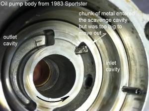 |  |  |
Affects of RPM
There is generally more flow loss at idle than at higher RPM due to Bernoulli's principle.
Higher RPM builds higher static pressure in the outlet side and reduces pressure toward the inlet side through the clearances or worn areas.
However, lower RPM reduces the static pressure in the outlet side allowing more flow to pass to the inlet side.
So it may not be such a problem on higher RPM (with light to moderate clearance wear) depending, but can be a concern if you have low pressure at idle.
As idle goes up, oil temp also goes up. So sustained high RPM will allow more internal leakage than intermittent high RPM.
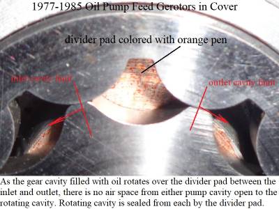
The 2 cavities (inlet and outlet respectively) act separate from one another due to the divider plate in the housing and hydraulic seal between inner and outer teeth.
In testing, pressure being suddenly restricted on the feed side had zero affect on the inlet vacuum.
And in turn, vacuum being suddenly restricted on the inlet side had zero affect on the outlet pressure.
The pump housing divider pad plays a roll in how oil is transferred from / to each housing cavity.
As the gear cavity travels from inlet to outlet, once the gear cavity is centered over the divider pad;
The pad covers the entire area of 1 tooth cavity plus 1/2 gear tooth radious.
The center of each adjacent inner gerotor tooth sits over the ending inlet and beginning outlet cavities in the housing.
So the only cross connect between the inlet and outlet cavities would come from the clearance between the inner and outer gear teeth.
The housing's inlet cavity ends under the inner tooth's largest OD as it sits adjacent to the outer gerotor.
The housing's outlet cavity begins under the inner tooth's largest OD as it sits adjacent to the out geotor.
Oil
How Pressure is Created
The pressure is generally created by restricting the flow of the fluid or by gravity.
Static Pressure vs Flow Pressure
It's important to distinguish the difference between flow pressure and static pressures as they both exist in the oil feed chain.
Static pressure (or hydrostatic pressure) is pressure that is resistant to flow.
It is not a measurement of much oil is flowing but rather the pressure that is being retained even though there is flow happening.
Static pressure is what we perceive as a snapshot reading of the total pressure available for the system to use at a given point in the feed chain. Static is what you see on your pressure gauge. It is also perceived as if it was absolute, as in a reading of the entire system. But static pressure can be either moving or completely still. When flow begins, the static pressure is lowered. That is not to say that the supply of oil is lowered if we are considering a continuous replenishing supply (as in the oil returning to the tank and recirculated as in our engines). Sportsters have a full (replenishing) supply of oil that is pumped out by way of flow which creates variable pressures within the oil feed chain. Static pressure is established at the oil pump and reduced to an extent by flow. The amount of static pressure reduction relies on the amount of pressure loss by the flow. A high flow condition will reduce static pressure more than a low flow condition. So the more oil that flows out, the lower the static pressure will be.
More often than not, there is hardly a time when the RPM stays the same for long on a Sportster.
Flow pressure (or dynamic pressure) is how fast the oil is moving, or being moved.
Flow pressure is important to note since the higher the flow, the less the static pressure becomes.
Flow pressure is related to flow volume (how much volume will come out of an orifice at a given point of RPM) and is variable by upstream pressure pushing it.
Higher RPM equals more pressure and more flow.
Flow pressure is measured with a Pitot Gauge in the center of the outlet stream closest to the outlet.
Since you can't put a pitot gauge on the outlets inside the engine to test their flow rates, equations need to be run to find that.
This article isn't going to get into equations and such but just a general overview of how the system operates.
The important thing to remember is that higher flow reduces and lower flow increases the pressure at the static gauge that you can use.
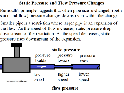
Bernoulli's Principle:
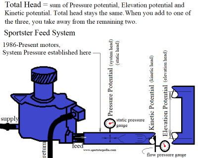
This is more efficiently defined in Bernoulli's Principle which relates the pressure, velocity, and height between two points along a fluid under certain conditions (incompressible, steady flow and non-viscous). The meaning of steady flow is “streamlined” (or not turbulent), as opposed to being the same speed or volume. It addresses fluid flow conditions, not fluid standing still. And it shows that pressure will not be the same throughout the Sportster oil feed system if you follow the oil path starting from the pump out. In Bernoulli's equation, when flow increases, flow pressure increases and static pressure decreases, while total pressure remains the same (constant). Total pressure = the sum of static pressure and flow pressure and elevation pressure changes.
You can read more on Bernoulli's principles on the internet. Click Here to read more from NASA's website.
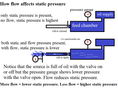
Closed vs Open System:
The drawing on the left below illustrates the fact that oil standing still in a pressurized chamber has a certain static pressure.
This is a closed system where there is no flow from the chamber. There are closed systems where oil flow is piped back into the supply tank without being relieved.
The Sportster oil system is not a closed system as it flows thru outlets that drop into the non pressured crankcase or gearcase then pumped back to the tank.
So there is an atmospheric break in-between the pressured loop.
Once flow begins, the static pressure drops even though the amount of oil in the chamber does not drop due to more incoming supply.
The flow is using up some of the original (total) static pressure. The result is considered “working pressure” or “residual pressure”.
Residual meaning, after the affects of flow have taken their toll and what the pressure is at during flow conditions.
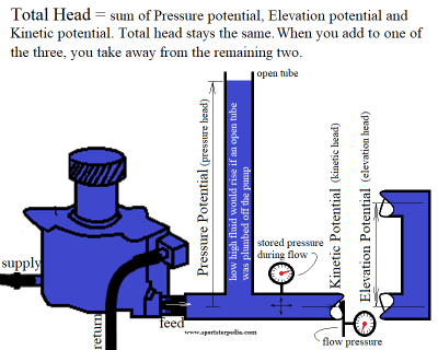
The drawing on the right below illustrates changes in the feed path as described by Bernoulli's principle showing ways the pressure changes along the path.
Static / Flow Pressure Relationship
The static pressure is the pressure pushing on the walls. The flow pressure is the elusive pressure gradient driving the motion of the fluid. 36)
The sum of the two is called stagnation pressure.
By the law of conservation of energy (Bernoulli's Principle); 37)
For any moving fluid it's “energy content” remains the same. What that means is the Total Pressure remains the same.
Total pressure = Potential pressure + Kinetic pressure + Elevation pressure.
If you add or remove pressure from one of the three, you subtract that amount from the remaining two pressures.
So if you increase the velocity (flow pressure), the potential pressure and elevation pressures (static) must drop to keep energy the same.
Likewise, if you decrease the velocity (flow pressure), the potential (static) pressure and elevation pressure must rise to keep energy the same.
Static pressure can also be thought of as stored energy where flow pressure can be thought of as moving pressure.
These two conditions revolve around each other.
If you pump “X” amount of pressure in a line and close off all the exits, the pressure stays at “X” (assuming there are no leaks).
However, the Sportster oiling system does not have closed exits. It's always flowing when the motor is running.
So in operation, if you pump a constant 25 PSI of static (gauge) pressure in the system and the exits through the system flow a total of constant 10 PSI out;
Your gauge pressure will read 15 PSI (15 PSI of stored pressure + 10 PSI of flow pressure).
These would be considered “working pressures”.
The static pressure is created due to restrictions.
Static pressure rises as RPM rises because you are not flowing as much pressure as you are storing.
If the outlets were more numerous or larger, the static gauge pressure would be lower since more oil pressure would be flowing out than is being stored.
Bringing this back to Bernoulli's principle and applying it to the Sportster, how come higher flow creates higher gauge pressure?
Applying Bernoulli's principle is most effective when the flow is laminar (steady). Turbulence throws the principle out of kilter.
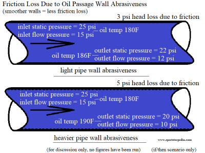
Friction in the feed passages creates higher static (gauge) pressure. The higher the flow rate, the higher the affects from friction.
See below.
Friction Loss
Friction is the force resisting the relative motion of solid surfaces, fluid layers, and material elements sliding against each other. 38)
Friction can also be exchanged with the word “drag” as friction causes fluid to drag along the walls of the passages.
There are several types of Friction.
- Dry friction resists the relative lateral motion of two solid surfaces in contact.
Dry friction occurs in the oil pump between the gerotors and divider plate(s) / pump housing.
(if you don't oil the gerotors before installing the pump) - Fluid friction describes the friction between layers of a viscous fluid that are moving relative to each other.
Fluid friction is a force that restricts the movement either within itself or of another medium moving through the liquid.
Due to the movement of the molecules inside the fluid, internal friction occurs, and how the fluid interacts with other matter, external conflict occurs.
The internal resistance to flow is termed as viscosity. The less-dense the fluid, the greater is the ease for movement or frictional force.- If there is a wet surface between two thin glass plates, you will notice that plates get stuck and the bottom plate doesn’t fall when you hold only the top one.
When any object is dropped in a fluid, the extent of the splash is depended on the fluid friction of that particular fluid.
You find lighter dust particles move fast on the surface of a flowing river.
This is due to the high-velocity gradient at the top layer of water due to lower dynamic fluid friction at that layer.
- Lubricated friction is a case of fluid friction where a lubricant fluid separates two solid surfaces.
Lubricated friction occurs in the oil pump between the divider plate(s) / pump housing and gerotors.
It also occurs between bearings and races. - Skin friction is a component of drag, the force resisting the motion of a fluid across the surface of a body.
A fluid flowing through a pipe contacts the pipe wall.
The pipe wall has surface roughness. The amount of roughness affects the drag on the fluid. 39)
Roughness is measured by the height of the projections sticking up from the pipe wall.
In the valleys between the projections, the fluid moves slowly. Above the projections it moves faster.
The drag between layers tears, or shears, them apart and each layer moves at a different speed.
The shear rate decreases as the distance from the wall increases. The velocity at the wall is zero and fastest at the center.
This means the central core of the fluid exits the pipe first.
So friction loss is the resistance of fluid to flow through a pipe by viscous shear stresses and turbulence that occurs along the internal pipe wall. 40)
These are dependent on the roughness of the pipe material.
This resistance is usually measured in feet or meters of head of the fluid, which is why it is also referred to as the head loss due to pipe friction.
The longer the run of pipe / hose, the higher the affects of friction on head pressure. - Internal friction is the force resisting motion between the elements making up a solid material while it undergoes deformation.
Internal friction is better defined in solid materials such as soil, rock, woods etc and not liquids and gases.
(as in particles of a soil body as two solid blocks sitting on top of each other)
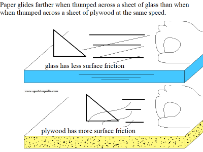
The drawing to the left below represents Dry Friction.
The drawing to the right below represents Skin Friction. The figures in the drawing drawing are just hypothetical numbers.
But the point is that friction lowers incoming pressure to lower pressure on the outlet of a straight run of pipe / hose.
Viscosity and Density Effects
Liquids are categorized by their behaviors when undergoing shear. 43)
Those liquids that have a constant shear rate with change of velocity (like water and oil) are called Newtonian fluids.
Newton first developed the mathematical explanation for the phenomenon.
Those with shear rates that vary with changing velocity (like paint and blood) are Non-Newtonian.
The shear rate is a measure of a fluid’s viscosity or slipperiness.
The density of a fluid affects its viscosity. Fluids with more mass per unit volume are heavier and require more energy to move them and shear less easily. 44)
A temperature rise decreases the viscosity and density of liquids. The more viscous, or less slippery, a fluid the harder it is to get shearing between layers.
The high viscosity prevents rapid velocity changes occurring between layers.
The sub layer in viscous fluids is thicker than in low viscosity fluids.
Affects of Velocity
At low speeds the whole flow across a pipe is laminar and the fluid slides over itself. As the speed becomes faster, eddies start to form and cross the fluid layers. 45)
A transition from laminar to turbulent flow develops.
At still higher velocities the flow in the core of the pipe becomes turbulent with swirling eddies throughout.
How Friction Lowers Flow
Bernoulli's equation is simply an energy balance equation, and in Bernoulli's, pressure drop is considered.
The pressure drop can be shown with the momentum balance equation. Pressure is simply force per unit area.
Fluids 'move' from high pressure to low pressure.
The shear forces, imposed by the boundary or pipe wall, oppose fluid motion so the pressure must drop consequently at the walls.
Force represents a change in momentum.
In fluid mechanics, one has the Navier-Stokes equations: continuity, momentum and energy, although some use Navier-Stokes equation in reference to the momentum equation.
Pressure loss from friction at bends and fittings is considered a minor loss (even though the loss itself may be significant). 46)
You will have pressure differentials using fittings with restricted IDs however. Friction loss from passage wall / hose composition is considered a major loss.
The greater the friction (and viscosity) the greater the resistance (opposition) to motion. 47)
Pressure loss in a pipe, which are associated with frictional energy loss per length of the pipe, depends on the flow velocity, pipe length, pipe diameter, and a friction factor based on the roughness of the pipe and whether the flow is laminar or turbulent (i.e., the Reynolds number of the flow). Although the pressure loss represents a loss of energy, it does not represent a loss of total energy of the fluid. The total energy of the fluid is conserved as a consequence of the law of conservation of energy. In reality, the head loss due to friction results in an equivalent increase in the fluid’s internal energy (temperature increases). 48)
Head Pressure
In general, the hydraulic head, or total head, is a measure of the potential of fluid at the measurement point.
It can be used to determine a hydraulic gradient between two or more points.
In fluid dynamics, head is a concept that relates the energy in an incompressible fluid to the height of an equivalent static column of that fluid.
The units for all the different forms of energy in the Bernoulli’s equation can be measured also in units of distance.
Therefore these terms are sometimes referred to as “heads” (pressure head, velocity head, and elevation head).
Head is also defined for pumps.
Head pressure as defined for pumps is usually referred to as the static head. It represents the maximum (pressure) the pump can deliver. 50)
Therefore the characteristics of all pumps can be usually read from its Q-H curve (flow rate – height).
Sportster static head (how much pressure is available at that moment to move) is variable due to RPM.
There are four types of potential (head):
- Pressure potential - Pressure head:
The pressure head represents the flow energy of a column of fluid whose weight is equivalent to the pressure of the fluid.
In the Sportster feed system, initial potential head pressure is established at the oil pump.
The rotating of the gears and the pressure when they compress establishes the initial point of flow.
If the gears stop moving, pressure potential from the pump stops since tank gravity doesn't make it past the inlet.
The amount of potential flow is set by RPM (slow speed = less pressured flow, fast speed = more pressured flow). - Elevation potential – Elevation head:
The elevation head represents the potential energy of a fluid due to it's elevation above a reference level.
Gravity from the oil tank does not add any energy on the feed side of the pump.
That energy stops at the pump inlet. - Kinetic potential – Kinetic head:
The kinetic head represents the kinetic energy of the fluid. It is the height in feet that a flowing fluid would rise in a column if all of its kinetic energy were converted to potential energy. Kinetic energy is (flow pressure). - Total Head: The sum of the elevation head, kinetic head, and pressure head of a fluid is called the total head.
The above three phases of head can change with the exception of Bernoulli’s principle stating that the total head of the fluid is constant.
So when you add to one of the three, you take away from the remaining two.
Head Loss from Bends / Fittings
In industry, any pipe system contains different technological elements as bends, fittings, valves or heated channels. 52)
These additional components add to the overall head loss of the system.
Such losses are generally termed minor losses, although they often account for a major portion of the head loss.
For relatively short pipe systems, with a relatively large number of bends and fittings (Sportster oiling system) minor losses can easily exceed major losses.
The minor losses are commonly measured experimentally. The data, especially for valves, are somewhat dependent upon the particular manufacturer’s design.
Like pipe friction, the minor losses are roughly proportional to the square of the flow rate and therefore they can be easy integrated into the Darcy-Weisbach equation.
The flow through elbows is quite complicated. In fact, any curved pipe always induces a larger loss than the simple straight pipe. 53)
This is due to the fact in a curved pipe the flow separates on the curved walls.
For very small radius of curvature the incoming flow is even unable to make the turn at the bend.
Therefore, the flow separates and in part stagnates against the opposite side of the pipe.
In this part of the bend the pressure raises (as a result of the Bernoulli’s principle) and the velocity decreases.
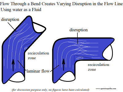
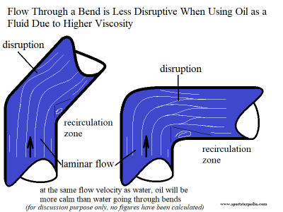
Below are examples of turbulence through conventional bends. The exact patterns and complexity of disruption will vary. See above.
The flow speed in both drawings below is the same. The drawings reflect a change in flow disturbance due to viscosity.
You can see that there is more disruption to the flow through a 90° bend as opposed to a 45° bend (and even less when using a 22-1/2° bend).
Notice that the rounded corner on most 90° bends helps the fluid flow around the corner with less disruption than a squared turn will.
 54)
54)  55)
55)
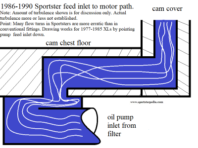
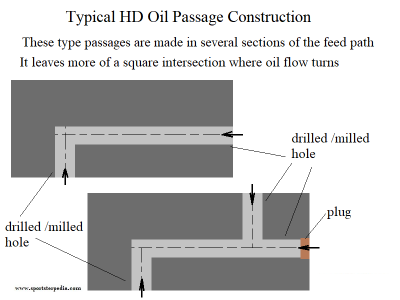
Below are some examples of how passages in Sportsters are hindered by the design of turns in the oil flow.
Stream Quality
Laminar
In fluid dynamics, laminar flow is characterized by smooth (or in regular paths) of particles of the fluid.
The fluid flows in parallel layers (with minimal lateral mixing), with no disruption between the layers.
Therefore the laminar flow is also referred to as streamline or viscous flow.
The term streamline flow is descriptive of the flow.
In laminar flow, layers of fluid flowing over one another at different speeds with virtually no mixing between layers.
Fluid particles move in definite and observable paths or streamlines.
For practical purposes, if the Reynolds number is less than 2000, the flow is laminar 58).
Per Tony R. Kuphaldt, laminar flow is something that only happens when viscous forces overshadow inertial forces (e.g. flow at low Reynolds numbers).
An it is totally different from the fully developed turbulent flow that orifice plates need for accurate measurement. 59)
Turbulent
As for the potential of oil flow to become turbulent, the possibility is surely there.
Every time a fluid makes a sudden turn (elbow) or expands or contracts (fittings), it experiences extra turbulence, which creates an additional loss of pressure. 61)
But due to it's viscosity at operating temp, oil flow is less likely to become turbulent than water flow due to oil having a higher viscosity at it's operating temp.
The effects you see on top of the water in a stream is usually cited to example the difference between calm and turbulence.
Some times of the year it'll flow along smoothly and calmly, but at others it'll turn into a raging, turbulent mass of water.
The transition between these two behaviours is linked to the Reynolds number.
This is a quantity that can be associated to any fluid flow (water, oil, blood, honey, gases etc).
You can picture a fluid flowing smoothly down a tube and then what factors that might cause that flow to become turbulent.
If the flow conditions downstream permit, turbulence will subside. However, beginning turbulence can be multiplied by downstream conditions as well.
- Velocity (speed of the flow):
As you increase fluid velocity, turbulence will eventually set in when the fluid gets so fast.
And conversely, turbulence subsides when the velocity decreases. - Viscosity:
It's harder to force a stream of honey to become turbulent than a stream of water which in turn won't become turbulent as easily a flow of air. - Diameter of the Tube / Passage: The passage diameter that the fluid flows thru also impacts on the nature of the flow.
A turbulent flow through a tube can be calmed down by putting a nozzle at the end of it (forcing the fluid to enter a smaller tube.
In reverse, a calm and steady laminar flow can become turbulent if the tube suddenly widens.
The larger the diameter of the tube, the easier it is for turbulence to happen, all other things being equal. - Bends / Turns:
Bends disrupt a steady stream of flow by causing the straight flowing particles to smash into the sides of a turn.
From inlet to outlet of a turn, the particles are forced into the wall, into each other in a rope winding fashion.
The flow is sped up through this transition and slows past the transition.
As long as the overall flow velocity isn't already too fast, the disruption dissipates downstream of the turn.
In general, this disruption (turbulence at the turn) is considered a “minor” disruption to the flow, as the flow recovers downstream. - Density of the Fluid (it's mass per unit volume):
The flow of a more dense fluid will create turbulence more easily than the flow of a lower density fluid, all other things being equal.
Osborne Reynolds, who experimented with fluids flowing down pipes in the 1880s, realized that it isn't the absolute values of these quantities that matter, but their relationship. If the fluid's speed and density and the diameter of the tube combined are sufficiently large to overwhelm the fluid's viscosity, then the fluid flow will be turbulent. If on the other hand viscosity is sufficiently large compared to the combination of speed, density and diameter, then the flow will be laminar, that is calm and smooth. 62)
Cavitation
Vaporous Cavitation is the rapid formation and subsequent collapse of vapor-filled cavities in a liquid. 63) 64)
We think of cavitation as in the lines to the pump running dry.
While that can be it's own issue, cavitation explained here is in the form of vapor bubbles out of nowhere.
When the oil enters the pump cavity, the decrease in flow area results in an increase in flow velocity accompanied by a decrease in static pressure. 65)
The greater the pump flow rate, the greater the pressure drop between the hose and the gears / gerotors.
If the pressure drop is large enough, or if the temperature is high enough, the pressure drop may be sufficient to cause the liquid to flash to vapor (boil).
(when the local pressure falls below the saturation pressure of the oil)
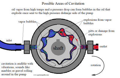
Any vapor bubbles formed by the pressure drop in the suction cavity is swept into the gear cavities.
When the bubbles enter a the discharge area, the greater pressure will collapse vapor bubbles abruptly.
This process involving the formation and subsequent collapse of vapor bubbles in the pump is called cavitation.
While vaporous cavitation is extremely rapid, occurring in microseconds, gaseous cavitation is much slower.
Gaseous cavitation (boiling) is a diffusion process that occurs whenever the pressure falls below the saturation pressure of the vapor particles dissolved in the liquid.
The time it takes depends upon the degree of convection (fluid circulation) present.
Possibility of cavitation can occur when vapor bubbles form in the suction line / suction cavity.
Possibility of cavitation increases as the pump head falls or as pump suction increases more than pump head delivers (from restrictions).
Centrifugal pumps operate at higher speeds and create higher (in pump) flow than positive displacement pumps and are easily susceptible to cavitation.
Cavitation wear occurs only under vaporous cavitation conditions (creates noise and shock waves - microjets can erode the surfaces).
Gaseous cavitation does not cause surface material to erode (just creates noise).
Any of these will create added heat.
Positive displacement pump gear / gerotor action can generate swirls that in the wrong condition, can generate vapor bubbles.
An aerated inlet hose can deliver vapor bubbles to the inlet cavity picked up by the gears and spin them around to the high pressure discharge cavity.
Once exposed in the high pressure cavity, the bubbles / vapors explode, reducing discharge pressure and possibly damaging the pump.
The size of the particles generated by cavitation wear is a function of the Brinell hardness of the exposed material.
The largest particles occur during the accumulation period.
The average size of the particles produced by cavitation decreases as the cavitation intensity increases.
Indications of cavitation:
- Noise: Cavitation sounds like marbles or gravel circulating through the pump or hoses.
- Vibration: Vibration happens when the bubbles explode in the high pressure zone.
- Internal pump damage: Microjets of oil pound and erode adjacent surfaces, pitted discharge cavity and/or gears.
Some causes of cavitation (causes of a pressure drop in the hose): 66)
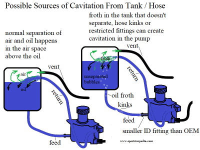
- Aerated oil in the tank not separating. The oil tank has an air space above the oil for a reason.
It gives room for air/oil mixtures (sent from the motor or pump) to separate.
The tank overall depth is a factor as a deep tank gives time for air separation before oil goes back into the pump.
Poor tank design can also churn the air into the oil or simply not allow air to be released from the oil.
This can be caused by kinked oil return lines, low oil level, a tank that is too small, lack of proper baffling, etc. - Oil tank / feed hose issues:
- Tank feed hose leaks. Leaks between the tank and the pump can introduce air into the suction area.
- Tank feed hose restriction. A feed hose from the tank that is kinked, has imploding walls or is otherwise plugged can cause it.
- Tank feed hose may be old and have it's walls collapsing.
- 2004-up plastic oil tanks have baffling and restricted venting. This has been shown to problematic for crankcase pressure.
But blocked up crankcase pressure also overpressures the tank and feed oil headed to the oil pump, increasing pump efficiency.
- Swapping the feed hose to a smaller ID. The added restriction can cause cavitation.
- Insufficient head (low oil level, high viscosity oil with too high rpm, etc, high location elevation above sea level).
- Air-release problems. As oils age and become contaminated, air-release properties become impaired.
This simply means that once air bubbles form, they stay locked into the matrix of the oil and don't detrain out of the oil in the reservoir.
Moisture contamination and oxidation are known precursors to this problem, among many others.
- Water vapor. When hot oils become contaminated with water, super-heated steam will form vapor bubbles in the oil.
- Gas vapor. Same as water vapor.
- High viscosity. When tank temps are too cold (wintertime startup), the viscosity may be too high to enable proper oil flow to the pump.
Other causes of high oil viscosity can lead to the same problem. - Sometimes a combination of the above can cause cavitation where a single instance will not.
To avoid cavitation, the NPSHA of the system must be greater than the NPSHR of the pump.
Tiny bubbles created by changes in pressure inside pumps collapse and create shock waves that occur over and over.
The repeated shocks erode the components.
Vapor Pressure
Cavitation is a dynamic phenomenon: Either the fluid is moving over something or something is moving thru the fluid. 69)
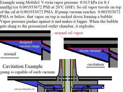
Vapor pressure rides on top of the oil. It is vapor pressure that needs to push the liquid away to create a bubble during cavitation.
Cavitation occurs in the pump when the fluid pressure drops below it's vapor pressure. 70)
This phenomena can occur by either increasing the temperature or reducing the pressure.
But in almost all cavitation cases, it's because the lowest pressure the fluid will experience in the system is the area immediately in front of the gears.
If the pressure in the fluid is below the vapor pressure, it will flash to vapor.
(not because of a temperature change, but because of a pressure change)
Atmospheric pressure does not affect vapor pressure, but does determine the vapor pressure at which boiling occurs. 71)
It doesn't take a long sustained stream to cause cavitation. Just the wrong amount of vacuum pulling on the liquid at a given point.
So you can have intermittent or sustained cavitation as well.
- Condensation (water) in the stream can lead to cavitation (vapor pressure at 68F, 0.334 PSIA) and (at 212F, 14.7 PSIA).
- In the US, gasoline vapor pressure limits may be from 7.8 PSIA to 9 PSIA depending on which state or area you live. 72)
- It's important to note that the vapor pressure of air is higher.
Air is made up of constituent gases, namely nitrogen, oxygen, argon, water vapor, and several trace gases. 73)
Vapor pressure of a constituent gas is the product of its mol% and the pressure of the mix.
Air is app. 80 mol% nitrogen, so the vapor pressure of N2 at sea level is 0.8 x 14.7 psia (11.76 PSIA).
Vapor pressure of Argon (1 mol%) is 0.01 x 14.7 (0.147 PSIA).
If you take a cup of liquid water and put it in a vacuum chamber, the liquid will turn to vapor and boil away.
You don't need to boil the liquid with heat; lowering the ambient pressure below the vapor pressure of the liquid is sufficient. 74)
Same thing happens with oil flow.
It is not that the pressure of the vapor gets high. It is that the pressure of the liquid gets low (low enough for vapor to form at the existing temperature). 75)
The vapor pressure just has to be greater than the ambient pressure in the fluid causing it to push into the stream.
1 atmosphere is about 29.92 hg (14.695332234620173 PSI).
The oil pump is perfectly capable of creating vacuum upwards of 10-14.7 PSI given the wrong circumstances.
Pressures logged on the 1991-1997 pump from bench testing were; feed inlet hose at -7.06 PSI, return inlet hose at -6.96 PSI at 2688 RPM pump RPM (5,376 engine RPM).
(return will be higher in real world conditions due to the return passage from the sump having a smaller ID)
Mobile1 V-twin vapor pressure is < 0.013 kPa (0.1 mmHg or 0.001933672 PSI) at 20°C (68F) 76)
According to Engineering Toolbox.com, that's app the same value as benzyl alcohol at that temp 77).
That is: 0.001933672 PSI above sea level or (14.7 PSI minus 0.001933672 PSI).
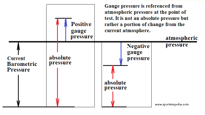
That is also absolute pressure and the testing readings are gauge pressure.
Vacuum gauge (g) pressure is (current atmosphere minus gauge reading).
On the bench with 40 cmHg vacuum at 79ºF with everything plumbed as it should be, the reading was “current” atmosphere minus -7.7346885078313 Psi.
Ok, that's halfway there. But, the motor is rarely at 68F.
That 0.001933672 figure printed from Mobile only applies at 68°F.
As the temp goes up, so does that vapor pressure.
Granted the viscosity comes down as temps go up which lowers vacuum also. But the restrictions in the oil path stay the same.
Lower viscosity only lowers vacuum from the pump so much. As the vapor pressure rises, and if vacuum doesn't decrease at the same rate;
You get even more vacuum pulling towards that “rising to meet” vapor pressure.
With oil at operating temp, cavitation seems more of concern on high revs. And vacuum is higher inside the pump than outside in the hose.
The thing about oil vapor pressure is it is comprised of base oil and many additives. Base oil has it's own vapor pressure as does each additive respectively.
So additive wear/viscosity breakdown from wear/gas entrained/air entrained etc. will all play a part in the actual vapor pressure at which the oil possesses.
Where Do Bubble Vapors Come From?
Any liquid (water, gas, oil etc.) will contain either gaseous or vaporous bubbles, which serve as the cavitation nuclei. 80)
When the pressure is reduced to a certain level (below atmosphere for example), vapor or dissolved gases pulled from the oil stream form into bubbles.
The oil's viscosity is also raised (gets thicker) with the more vapor that is removed.
The immediate result of this condition is that the bubbles increase rapidly in size.
This phenomenon can happen on the inlet side of the pump or between the gear mesh when gears rotate apart.
High temperature / high heat also allows the vapors to escape.
Oil won't evaporate like water does but vapors escaping (even when parked in summer heat) can lower the oil level in the tank over time.
Coupling a high pressure differential with high heat makes a recipe for cavitation.
Multi-Phase Fluids
Our motor oils are multi-phase fluids.
In fluid mechanics, multiphase flow is the simultaneous flow of materials with two or more thermodynamic phases. 81)
In our motors, multiphase flow generally is the simultaneous flow of oil, water (condensate) and gas.
Then solids introduced make the oil heavier (metal from wear).
Example: Salt dissolved in water forms a uniform mixture (salt solution). 82)
There is more than one compound there but they are perfectly mixed and seemingly flow as one liquid.
Mushy compounds of oil and debris at low temp/high viscosity drop out of the oil and variably disperse components as the oil heats up.
The separate phases can either be contained within the oil or as a separate stream alongside the oil.
The vapor pressure riding on top of the oil is an example of a separate stream.
Free air is an example of a separate stream. Microbubbles are an example of internal containment in the oil as is gas particles and foreign solids.
Each phase, representing a volume fraction (or mass fraction) of solid, liquid or gaseous matter, has its own properties, velocity, and temperature. 83)
There are many types of instabilities in multiphase flow.
Separate density of the phases affect the influence of gravitational force on multiphase flows.
The sound speed changes dramatically for materials undergoing phase change.
This significantly influences a flow through an orifice.
The speed of sound (phase speed) is the speed at which a pressure wave travels in the fluid and a function of a fluid’s density.
Example: If a valve closes at the end of a long pipeline;
The time it takes to observe an increase in pressure at the start of the pipeline can be calculated by dividing the pipe length by the speed of sound.
A change of phase means flow-induced pressure drops can cause further phase-change.
This would increase the relative volume of the gaseous, compressible medium and increase efflux velocities (water can evaporate through an orifice).
High vacuum in the oil stream can cavitate other portions of a multiphase fluid before it cavitates the oil stream.
Air and Entrained Air
Don't get too caught up in the fact that the Sportster oil pump is designed to move both air and oil.
Free air itself entering / leaving the return side isn't as big a deal as free air entering / leaving the feed side of the pump on our open systems.
Those with closed systems would heartedly disagree with that statement however.
Air can be present in four forms: 84)
- Free air
- Dissolved air
- Entrained air - air bubbles typically less than 1 mm in diameter dispersed in the oil.
- Foam - air bubbles typically greater than 1 mm in diameter that congregate on the surface of the oil.
Free Air
This is pockets of air as was shown in the return hose from testing (normal occurrence found in the tank from the crankcase).
These disburse rather quickly in the tank being larger pockets of air. The bigger picture regarding free air is it lowers cooling capacity of the oil.
And as long as we are talking within the return to tank path, free air is less of a concern as the other three forms of air.
The return pump will compress free air pockets that start pretty big already but the pump will also pull the oil behind into and along with free air pockets.
So a larger amount of force is being used up to pull the oil behind and into the pump.
As was in testing, residual oil was present in the cam chest inlet hose with feed oil removed from the stream.
You could see the oil pockets being moved to a point then air moved past them toward the pump inlet.
So the prevalent fluid gets the most energy in that case.
Dissolved Air
At any pressure, there is a possibility of air dissolved in oil (regardless of viscosity). 85)
Even a beaker of oil sitting on a table at atmospheric pressure may have some air dissolved, complete invisible to the naked eye.
In hydraulic systems, oil may be pressurized at some or all areas of the circuit.
Any air bubbles in the oil could become dissolved as the pressure increases. If the pressure decreases again, the dissolved air may return as air bubbles.
This is more like what was seen when the return hose was restricted in testing. Also lowers cooling capacity of oil.
Entrained Air
Air entrainment is a dispersion of tiny air bubbles into the oil. 86)
Oil under low pressure absorbs approximately 10% air by volume. With oil under high pressure, the percentage is even greater.
Entrained air refers specifically to air bubbles with diameters smaller than 1 mm contained within the oil.
Vacuum can pull them out of the oil, turbulence and high flow conditions can also.
High air entrainment in the system can contribute to pump cavitation.
The bubbles are dispersed through the oil during instances of turbulence or agitation.
(such as passing through restrictions, manipulated through the pump or churned in the crankcase)
How long air entrainment lasts in the system, once created, depends on the amount of time the oil is allowed to rest before recirculating.
The level of entrained air is a math problem between how fast it's entrained as opposed to how fast it's released.
It also depends on the viscosity of the oil at the time.
High viscosity (thick) oil is heavy all around the air bubbles and slows the time which they can rise and leave.
Entrained air also lowers cooling capacity of oil.
Foam
Foam (or froth) is a collection of small bubbles of air that accumulate on or near the surface of the fluid. 87)
When the fluid is depressurized, the air produces foam as it is released from solution.
Since entrained air is of a lower density than the oil, it will eventually rise to the surface in an attempt to escape. 88)
Once at the surface, the air will form thin liquid films (known as lamellae).
Depending on the strength of the lamellae and the rate of air added, a network of separate air chambers may form (otherwise known as foam).
The viscosity and surface tension effects the amount of foam that can form on the surface of the oil.
While small amounts of foam may not be cause for concern, larger amounts of foam and high air entrainment in the system can contribute to pump cavitation.
Foam in the oil tank normally rides on top of the oil and should dissipate before being pulled down into the feed hose.
Or rather, the oil level should not get low enough to allow foam to be extracted back into the feed system.
That is unless the production of foam is very heavy and continuous.
In that case, foam could be sucked back into the feed system and compound.
Some causes of foam include; 89)
- Water contamination
- Solids contamination
- Depleted defoamant (possibly due to the use of excessively fine filtration and electrostatic separation technologies)
- Mechanical issues (causing excessive aeration of the fluid)
- Overfilling of the sump with splash oil (wet sumping)
- Cross contamination of oil (with separate oil or with grease), read as creation of sludge
- Too much defoamant additive, either by incorrect formulation or by incorrect reconstruction (sweetening) of the additive package
Aeration
The oil travels through a complex network of passages.
The agitation of the fluid through these passages is a contributing factor in aerating oil as is the pistons / flywheels.
Air becomes bound to the oil as it splashes it's way through the system. 90)
(similar to how bubbles are formed when you splash water in a bathtub)
This phenomenon worsens as the velocity of the fluid increases (increased engine speed and/or reduced viscosity with temp or additives).
Once the oil is aerated, it will remain so until the air can escape. Aerated oil will recirculate in the tank with incoming oil from the pump.
Windage from the crankcase aerates oil and air / oil from splash in the bottom end is further de-aerated by collision.
Once the oil reaches the tank, the shorter the residence time there, the more aerated the oil will be going back into the system.
Also higher engine speeds reduce residence time in the tank.
Air can enter the oil system through the tank, crankcase, pump action, air leaks within the system, condensate (water is H2O) etc.
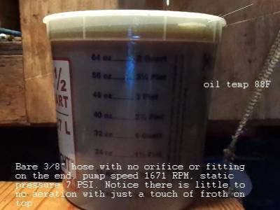
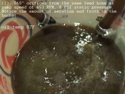
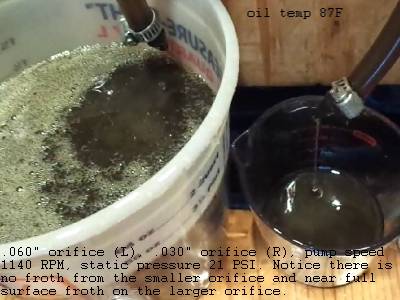
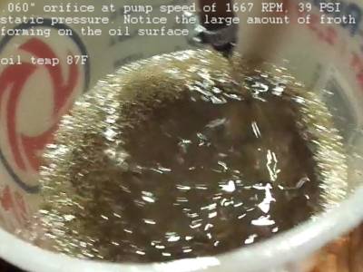
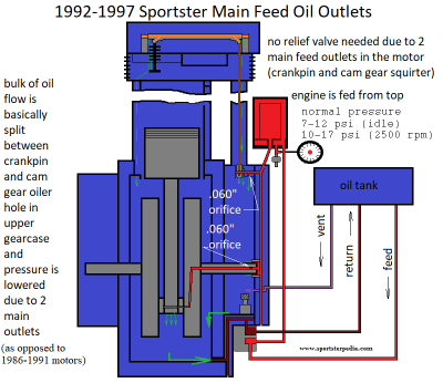
The pics below show the amount of aeration / froth generated by orifice size in testing.
The .060“ orifice generated much more aeration and froth than the .030” orifice (which only created light froth when over 50 PSI).
The pics show it's not the amount of flow that created aeration but rather at what pressure through what size orifice that created aeration.
Cooling Losses with Aeration
It's obvious our oiling system is designed to carry both oil and air out of the system.
Just not back into the system. Oil's purpose is to both lubricate and cool.
If you are bringing in increasing air bubbles along with the oil into the system, you are not cooling as much.
So air is not good to bring into the feed side.
Entrained air can alter the oil's ability to dissipate heat (increasing operating temp).
The oil tank is responsible for cooling the oil in a way. The oil tank's ability to separate air and oil is a cooling event for the oil as well.
The oil depends on time and space to aerate before recirculation and the tank provides this to the oil.
Aerated oil is hotter than non-aerated oil by default (less oil per mass).
The feed side of the pump is not responsible for cooling, just delivery. A continuous full stream of oil cools more than half oil / half air does.
The return side is not responsible for cooling either. It delivers oil, entrained air, gas, froth, crankcase air and debris to the tank.
The oil inside the tank benefits indirectly from outside airflow. The metal tank holds heat and is cooled by airflow.
The plastic oil tank dissipates heat itself and then you add the indirect affects of air flow.
Outside Air Doesn't Cool Oil
The motor is “air cooled” when running down the road. That doesn't mean as much for the oil as some might think.
It's designed to be in a certain temp range while running down the road.
The air moving past the motor while riding simply keeps heat from staying near the motor to further increase the temp.
Meanwhile, the inside of the motor is creating higher temps.
The oil reacts to the temp of it's surroundings (metal around it heats up, oil heats up because of it).
So if the heat coming off the motor is blown away from it, that keeps the heat from staying close to the motor and reaching even higher temps.
It also keeps the oil inside from reaching higher temps but air while riding down the road doesn't actually cool the oil.
The oil inside the motor doesn't directly receive the benefit of outside air flow.
Rather, the indirect benefit of the metal temp around it being controlled due to air flow does to a point.
Oil Separation
There are two main ways air is separated from oil, time and collision.
The oil tank is responsible for air/oil separation before the feed side pulls it back into the system.
Air space above the oil in the tank is there to allow air separation from the oil below.
Guys running the oil to the lower mark on the stick are also removing a certain amount of time for air/oil separation.
If you have less oil in the tank, there is less time for separation (less residence time) before it goes back into circulation.
Contaminates can hold entrained air in suspension also.
The longer the contaminates have to drop out of the oil, the more entrained air can rise to the surface into the air space above.
Transmission of Pressure
Entrained air also affects the oils ability to transmit pressure. 91)
The higher the pressure, the faster oil moves out the orifices and lower pressure equals lower flow.
Air is more easily compressed than the oil surrounding it so air bubbles entrained reduces the oil's resistance to compression.
This is more a problem with hydraulic use (pushing power) but it also slows flow to the point of reaction time thru orifices.
In the case of 1986-1991 Sportsters, entrained air could lengthen the time it takes to open the pressure relief valve for instance.
Oil Oxidation
Oil oxidation is another problem caused by air entrainment.
As a fluid is pressurized, the entrained air is compressed and increases in temperature.
This increased air temperature can be high enough to scorch the surrounding oil and cause oxidation.
The amount of foaming in a fluid depends upon the viscosity of the fluid, the source of the crude oil, the refinement process, and usage.
Foam depressants are commonly added to hydraulic fluid to expedite foam breakup and release of dissolved air.
However, it is important to note that foam depressants do not prevent foaming or inhibit air from dissolving in the fluid.
In fact, some anti-foamants, when used in high concentrations to break up foam, actually retard the release of dissolved air from the fluid.
Sources of Heat that Lead to Cavitation
Heat can be generated from the entire oiling path to cause vapors to separate out of the oil.
Some reasons for heat are below. 92)
- High ambient temperature
- Poor oil pump efficiency (including slippage and heavy loading)
- Turbulent flow conditions in the feed path
- Heat of vaporization in cavitating flow
- Heat of compression in aerated flow
- High pressure drops across orifices
- Severe pump duty
- Flow restrictions in all parts of the feed path
- Poor oil cooling or lack of heat transfer
- High friction from rough surfaces and abrasive action
NPSHR vs NPSHA
NPSHR is the (Net Positive Suction Head Required) by the pump.
It's the pressure or energy required for the liquid in a pump to overcome the friction losses from the suction nozzle to the gears without causing vaporization. 93)
It is the amount of positive suction head required by the pump to ensure proper operation. 94)
More simply, it is the amount of positive pressure in the tank hose required for the pump to suck up.
NPSHA is the (Net Positive Suction Head Available) to the pump.
This simply is the amount of positive pressure on the oil tank feed hose available to the pump.
The higher the pressure, the higher the NPSHA and the better the pump will operate. 95)
If the pump is sucking more pressure (NPSHR) than is available in the hose (NPSHA), the pump starts sucking fumes (vapor) off the oil.
(kind of like sucking a thick milkshake through a straw - the liquid is there but you can't get it out too fast)
This is also referred to as “boiling” the oil. The oil doesn't have to be a certain temperature to “boil”.
The fume molecules come together into a bubble that quickly gets bigger.
Orifices
Orifice: An orifice is a term given to an opening (such as a vent, mouth, or hole) through which something may pass. 97)
They are used to throttle, vent, bleed, or regulate the flow of liquids and gases. 98)
There are different types of orifices depending upon their size, shape, and nature of discharge. 99)
Technically, an anus is also an orifice. But for the purpose of this article, we'll refer to an orifice as a very small drilled hole.
According to size: small orifice or large orifice (Sportster orifices are of the small version).
According to shape: circular orifice, rectangular orifice or triangular orifice (you'll find circular orifices in the Sportster feed chain).
According to shape of edge: sharp-edged, bell-mouthed etc.
According to nature of discharge: submerged orifice (discharged inside the piping) or free discharged orifice (fluid outflows into atmosphere).
The restrictor orifice in the pinion shaft (evos) is submerged and the piston squirters (rubbermounts) are free flowing.
In particular, the Sportster feed passages have both submerged and free flowing orifices.
Submerged orifices are manipulated by pressure changes in the system and still possess some pressure energy depending upon the available head downstream.
Free flowing orifices are simply a product of the “current” system static pressures.
The higher the static pressure, the more the flow. Lower static pressure equals lower flow from the orifices.
Once the jet stream escapes the orifice, the entire pressure energy of oil is converted into kinetic energy.
Then the jets (example, piston squirters on rubbermounts) are subjected to / manipulated by crankcase pressure once they leave their orifices.
Jet Stream: The continuous stream of a liquid, that comes out or flows out of an orifice, is known as the jet stream.
Vena Contracta: To the flow rate through an orifice, a horizontal jet of fluid emerges on the downstream of the orifice.
The jet narrows over a short distance beyond (downstream of) the orifice. 100)
This narrowing of the stream is generally known as a vena contracta (contracted vein).
The jet is bound to narrow in this manner because of the curvature of the lines of flow as they pass through the orifice.
The liquid particles, in order to flow out through the orifice, move towards the orifice from all directions.
A few of the particles first move downward, then take a turn to enter into the orifice and then finally flow through it. 101)
The distance of the vena contracta from the orifice is approximately equal to one-half the depth or diameter of the orifice. 102)
The stream lines of flow are converging up to vena contracta and beyond this section the stream lines are parallel.
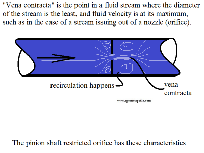 103)
103)
Orifice coefficient: Or (hydraulic coefficient) 104)
In hydraulics, it is the effect of a nozzle (or orifice) on a fluid discharge. 105)
Fluid under pressure has a certain potential energy. When discharged through an orifice, this energy is converted to kinetic energy.
How efficiently this occurs depends on the geometry and quality of the orifice.
The coefficient of discharge is the ratio of the amount of fluid discharged to the amount theoretically possible at that pressure from an opening of that area.
This characterizes the parameters that affect the flow through an orifice. 106)
This is a dimensionless number used to characterize the flow and pressure loss behavior of nozzles / orifices in fluid systems.
Typical values of the discharge coefficient for common orifice and nozzle designs are below.
- Coefficient Of Contraction
The ratio of the area of the jet, at vena-contracta, to the area of the orifice.
The value of Coefficient of contraction varies slightly with the available head of the liquid, size and shape of the orifice. - Coefficient Of Velocity
The ratio of actual velocity of the jet, at vena-contracta, to the theoretical velocity.
The difference between the velocities is due to friction of the orifice.
The value of Coefficient of velocity varies slightly with the different shapes of the edges of the orifice.
This value is very small for sharp-edged orifices. For a sharp edged orifice, the value increases with the head pressure. - Coefficient Of Discharge
The ratio of a actual discharge through an orifice to the theoretical discharge. The value of coefficient of discharge varies with the velocity and contraction coefficients. - Coefficient Of Resistance
The ratio of loss of head in the orifice to the head of water available at the exit of the orifice.
The loss of head in the orifice takes place, because the walls of the orifice offer some resistance to the liquid as it comes out.
The coefficient of resistance is generally neglected, while solving numerical problems but still exist.
The drawing below was created using a drawing from FluidPower.com as reference. 107)
A coefficient of (.61) suggests the vena contracta is app 61% of the ID of the orifice.
Restriction Orifice
Restriction orifices (example - the orifice in the Evo pinion shafts) are applied in a pipe to regulate the flow rate or pressure. 109)
Restriction orifices reduce the flow rate by introducing an additional pressure drop in the pipe (downstream of the orifice). 110)
They also reduce static pressure downstream and increase static pressure upstream of the orifice.
A restriction orifice is also very poor at recovering pressure downstream.
Pressure drops because of the sudden change in pipe-to-orifice diameters which force the flow to change direction very rapidly down stream of the orifice. 111)
That requires high acceleration of the fluid molecules and high acceleration requires a lot of energy.
That reduces the available energy downstream of the orifice, which manifests as lower pressure.
On the test rig below for a 1991-1997 oil pump, a 3/8“ x 1/4” tee was added inline on the return hose (simulating sump to pump oil passage) for a vacuum gauge.
An air pocket was found at the outlet side of the tee during oil flow. Air was already present in the hose due to installing the tee.
When the flow was shut down, the air pocket walked up to the high point in the hose (to the right of tee in the pic below).
When starting the pump again, the air pocket flows into the pump and back to the bucket. No more air at the tee.
The end of the tee is being sucked on by the pump.
This is an example of what happens to the flow when it goes thru a restriction.
(in this case, coming from a restricted space, smaller tee ID, to a more open space being the bigger hose ID)
The tee ID is (.210“), vacuum on the return hose was 14cmHg (app -2.71 psi) and pump speed was 657.4 RPM.
The air pocket stays there around the tee as does the oil directly around the air pocket.
This is also an example of oil moving in the center but not on the sides.
You can see the vena contracta and recirculation pockets on the right side of the tee in the pic below.
If the air hadn't got locked up in the recirculation zone, the phenomenon wouldn't have been seen.
But this proves that it does exist even though.
That area is a source of turbulence and heat generation as are other areas in the oil path that have the same qualities.
The video below shows an air pocket bouncing around past the restriction ID of a tee. (recirculating but not moving downstream with the center oil stream).
| Pic of air appearing out of nowhere with hose restricted by pliers 113) |
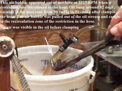 |
Flow Rates
Velocity through a line can be calculated with the formula: Velocity (FPS) = (GPM x 0.3208) ÷ Area
Velocity = Feet Per Second (fps)
GPM = Gallon per minute fluid flow
Area = Area (in square inch) of inside diameter of hose / passage calculated as (π x R²)
Womack Machine Supply Co. has a fluid velocity calculator for oil in general for fluid and piping calculations. 118)
Their suggestions for pipe sizing / fluid velocity are;
- Pump suction lines should be sized so the fluid velocity is between 2 and 4 feet per second.
If the velocity gets too fast, by default vacuum is higher, and the vacuum will suck air out of the oil.
Correctly sized suction lines create a slower, less turbulent fluid stream. - Oil return lines should be sized so the fluid velocity is between 10 and 15 feet per second for low pressure lines (0-100 PSI).
Flow Rate Chart for Water
These figures are for water through orifices and do not represent oil flow through orifices.
Oil flow at operating temp will be different due to oil having a higher viscosity.
Water is basically regarded as having no viscosity.
The chart below is a reprint from Senninger.com. 119)
| Nozzle Orifice Size | 6 psi 0.41 bar | 10 psi 0.69 bar | 15 psi 1.03 bar | 20 psi 1.38 bar | 25 psi 1.72 bar | 30 psi 2.07 bar | 35 psi 2.42 bar | 40 psi 2.76 bar | 50 psi 3.45 bar |
|||||||||
| gpm | L/hr) | gpm | L/hr) | gpm | L/hr) | gpm | L/hr) | gpm | L/hr) | gpm | L/hr) | gpm | L/hr) | gpm | L/hr) | gpm | L/hr) | |
| 1/32” (0.79 mm) | 0.07 | 16 | 0.09 | 20 | 0.11 | 25 | 0.12 | 27 | 0.14 | 32 | 0.15 | 34 | 0.16 | 36 | 0.18 | 41 | 0.20 | 45 |
| 5/128“ (0.99 mm) | 0.11 | 25 | 0.14 | 32 | 0.17 | 39 | 0.19 | 43 | 0.22 | 50 | 0.24 | 55 | 0.26 | 59 | 0.28 | 64 | 0.31 | 70 |
| 3/64” (1.19 mm) | 0.15 | 34 | 0.20 | 45 | 0.24 | 55 | 0.28 | 64 | 0.31 | 70 | 0.34 | 77 | 0.37 | 84 | 0.40 | 91 | 0.44 | 100 |
| 7/128“ (1.4 mm) | 0.21 | 48 | 0.27 | 61 | 0.33 | 75 | 0.38 | 86 | 0.43 | 98 | 0.47 | 107 | 0.50 | 114 | 0.54 | 123 | 0.60 | 136 |
| 1/16” (1.59 mm) | 0.27 | 61 | 0.35 | 79 | 0.43 | 98 | 0.50 | 114 | 0.56 | 127 | 0.61 | 139 | 0.66 | 150 | 0.70 | 159 | 0.79 | 179 |
| 9/128“ (1.78 mm) | 0.35 | 79 | 0.45 | 102 | 0.55 | 125 | 0.63 | 143 | 0.71 | 161 | 0.77 | 175 | 0.84 | 191 | 0.89 | 202 | 1.00 | 227 |
| 5/64” (1.98 mm) | 0.43 | 98 | 0.55 | 125 | 0.68 | 154 | 0.78 | 177 | 0.87 | 198 | 0.96 | 218 | 1.04 | 236 | 1.11 | 252 | 1.24 | 282 |
| 11/128“ (2.16 mm) | 0.52 | 118 | 0.67 | 152 | 0.82 | 186 | 0.95 | 216 | 1.06 | 241 | 1.16 | 263 | 1.26 | 286 | 1.34 | 304 | 1.50 | 341 |
| 3/32” (2.38 mm) | 0.62 | 141 | 0.80 | 182 | 0.98 | 223 | 1.13 | 257 | 1.26 | 286 | 1.38 | 313 | 1.50 | 341 | 1.60 | 363 | 1.79 | 407 |
| 13/128“ (2.59 mm) | 0.73 | 166 | 0.94 | 213 | 1.15 | 261 | 1.33 | 302 | 1.49 | 338 | 1.63 | 370 | 1.76 | 400 | 1.88 | 427 | 2.10 | 477 |
| 7/64” (2.78 mm) | 0.85 | 193 | 1.09 | 248 | 1.34 | 304 | 1.54 | 350 | 1.73 | 393 | 1.89 | 429 | 2.04 | 463 | 2.18 | 495 | 2.44 | 554 |
| 15/128“ (2.97 mm) | 0.97 | 220 | 1.26 | 286 | 1.54 | 350 | 1.77 | 402 | 1.98 | 450 | 2.17 | 493 | 2.35 | 534 | 2.51 | 570 | 2.81 | 638 |
| 1/8” (3.18 mm) | 1.11 | 252 | 1.43 | 325 | 1.75 | 397 | 2.02 | 459 | 2.26 | 513 | 2.48 | 563 | 2.68 | 609 | 2.86 | 650 | 3.20 | 727 |
| 17/128“ (3.38 mm) | 1.25 | 284 | 1.62 | 368 | 1.98 | 450 | 2.29 | 520 | 2.56 | 581 | 2.80 | 636 | 3.02 | 686 | 3.23 | 734 | 3.61 | 820 |
| 9/64” (3.57 mm) | 1.40 | 318 | 1.81 | 411 | 2.22 | 504 | 2.56 | 581 | 2.87 | 652 | 3.14 | 713 | 3.39 | 770 | 3.63 | 824 | 4.06 | 922 |
| 19/128“ (3.76 mm) | 1.57 | 357 | 2.02 | 459 | 2.48 | 563 | 2.86 | 650 | 3.20 | 727 | 3.50 | 795 | 3.78 | 859 | 4.04 | 918 | 4.52 | 1027 |
| 5/32” (3.97 mm) | 1.74 | 395 | 2.24 | 509 | 2.75 | 625 | 3.17 | 720 | 3.55 | 806 | 3.88 | 881 | 4.20 | 954 | 4.49 | 1020 | 5.01 | 1138 |
| 21/128“ (4.17 mm) | 1.92 | 436 | 2.47 | 561 | 3.03 | 688 | 3.50 | 795 | 3.91 | 888 | 4.29 | 974 | 4.63 | 1052 | 4.95 | 1124 | 5.53 | 1256 |
| 11/64” (4.37 mm) | 2.10 | 477 | 2.72 | 618 | 3.33 | 756 | 3.84 | 872 | 4.30 | 977 | 4.71 | 1070 | 5.08 | 1154 | 5.43 | 1233 | 6.08 | 1381 |
| 23/128“ (4.57 mm) | 2.30 | 522 | 2.97 | 675 | 3.64 | 827 | 4.20 | 954 | 4.70 | 1067 | 5.15 | 1170 | 5.56 | 1263 | 5.94 | 1349 | 6.65 | 1510 |
| 3/16” (4.76 mm) | 2.51 | 570 | 3.24 | 736 | 3.97 | 902 | 4.58 | 1040 | 5.12 | 1163 | 5.61 | 1274 | 6.06 | 1376 | 6.48 | 1472 | 7.24 | 1644 |
| 25/128“ (4.95 mm) | 2.72 | 618 | 3.52 | 799 | 4.31 | 979 | 4.97 | 1129 | 5.56 | 1263 | 6.09 | 1383 | 6.58 | 1494 | 7.03 | 1597 | 7.86 | 1785 |
| 13/64” (5.16 mm) | 2.95 | 670 | 3.81 | 865 | 4.66 | 1058 | 5.38 | 1222 | 6.02 | 1367 | 6.59 | 1497 | 7.12 | 1617 | 7.61 | 1728 | 8.51 | 1933 |
| 27/128“ (5.36 mm) | 3.18 | 722 | 4.11 | 933 | 5.03 | 1142 | 5.81 | 1320 | 6.49 | 1474 | 7.11 | 1615 | 7.68 | 1744 | 8.21 | 1865 | 9.18 | 2085 |
| 7/32” (5.56 mm) | 3.42 | 777 | 4.42 | 1004 | 5.41 | 1229 | 6.25 | 1420 | 6.99 | 1588 | 7.65 | 1738 | 8.27 | 1878 | 8.84 | 2008 | 9.88 | 2244 |
| 29/128“ (5.77 mm) | 3.67 | 834 | 4.74 | 1077 | 5.81 | 1320 | 6.71 | 1524 | 7.50 | 1703 | 8.21 | 1865 | 8.87 | 2015 | 9.48 | 2153 | 10.60 | 2408 |
| 15/64” (5.95 mm) | 3.93 | 893 | 5.08 | 1154 | 6.22 | 1413 | 7.18 | 1631 | 8.03 | 1824 | 8.79 | 1996 | 9.50 | 2158 | 10.15 | 2305 | 11.35 | 2578 |
| 31/128“ (6.15 mm) | 4.20 | 954 | 5.42 | 1231 | 6.64 | 1508 | 7.67 | 1742 | 8.57 | 1946 | 9.39 | 2133 | 10.14 | 2303 | 10.84 | 2462 | 12.12 | 2753 |
| 1/4” (6.35 mm) | 4.48 | 1018 | 5.78 | 1313 | 7.08 | 1608 | 8.17 | 1856 | 9.14 | 2076 | 10.01 | 2274 | 10.81 | 2455 | 11.56 | 2626 | 12.92 | 2934 |
| 33/128“ (6.55 mm) | 4.76 | 1081 | 6.15 | 1397 | 7.53 | 1710 | 8.69 | 1974 | 9.72 | 2208 | 10.65 | 2419 | 11.50 | 2612 | 12.30 | 2794 | 13.75 | 3123 |
| 17/64” (6.75 mm) | 5.06 | 1149 | 6.53 | 1483 | 7.99 | 1815 | 9.23 | 2096 | 10.32 | 2344 | 11.31 | 2569 | 12.21 | 2773 | 13.06 | 2966 | 14.60 | 3316 |
| 35/128“ (6.93 mm) | 5.36 | 1217 | 6.92 | 1572 | 8.47 | 1924 | 9.78 | 2221 | 10.94 | 2485 | 11.98 | 2721 | 12.94 | 2939 | 13.84 | 3143 | 15.47 | 3514 |
| 9/32” (7.14 mm) | 5.67 | 1288 | 7.32 | 1663 | 8.96 | 2035 | 10.35 | 2351 | 11.57 | 2628 | 12.68 | 2880 | 13.69 | 3109 | 14.64 | 3325 | 16.37 | 3718 |
| 37/128“ (7.34 mm) | 5.99 | 1360 | 7.73 | 1756 | 9.47 | 2151 | 10.93 | 2482 | 12.22 | 2775 | 13.39 | 3041 | 14.46 | 3284 | 15.46 | 3511 | 17.28 | 3925 |
| 19/64” (7.54 mm) | 6.31 | 1433 | 8.15 | 1851 | 9.98 | 2267 | 11.53 | 2619 | 12.89 | 2928 | 14.12 | 3207 | 15.25 | 3464 | 16.30 | 3702 | 18.23 | 4140 |
| 39/128“ (7.75 mm) | 6.65 | 1510 | 8.58 | 1949 | 10.51 | 2387 | 12.14 | 2757 | 13.57 | 3082 | 14.86 | 3375 | 16.05 | 3645 | 17.16 | 3897 | 19.19 | 4359 |
| 5/16” (7.94 mm) | 6.99 | 1588 | 9.02 | 2049 | 11.05 | 2510 | 12.76 | 2898 | 14.27 | 3241 | 15.63 | 3550 | 16.88 | 3834 | 18.05 | 4100 | 20.18 | 4583 |
| 41/128“ (8.13 mm) | 7.34 | 1667 | 9.47 | 2151 | 11.60 | 2635 | 13.40 | 3043 | 14.98 | 3402 | 16.41 | 3727 | 17.72 | 4025 | 18.95 | 4304 | 21.18 | 4811 |
| 21/64” (8.33 mm) | 7.70 | 1749 | 9.93 | 2255 | 12.17 | 2764 | 14.05 | 3191 | 15.71 | 3568 | 17.21 | 3909 | 18.59 | 4222 | 19.87 | 4513 | 22.21 | 5044 |
| 43/128“ (8.53 mm) | 8.06 | 1831 | 10.40 | 2362 | 12.74 | 2894 | 14.71 | 3341 | 16.45 | 3736 | 18.02 | 4093 | 19.46 | 4420 | 20.80 | 4724 | 23.26 | 5283 |
| 11/32” (8.73 mm) | 8.43 | 1915 | 10.88 | 2471 | 13.33 | 3028 | 15.39 | 3495 | 17.20 | 3907 | 18.85 | 4281 | 20.36 | 4624 | 21.76 | 4942 | 24.33 | 5526 |
| 45/128“ (8.94 mm) | 8.81 | 2001 | 11.37 | 2582 | 13.92 | 3162 | 16.08 | 3652 | 17.98 | 4084 | 19.69 | 4472 | 21.27 | 4831 | 22.74 | 5165 | 25.42 | 5774 |
| 23/64” (9.13 mm) | 9.19 | 2087 | 11.87 | 2696 | 14.54 | 3302 | 16.78 | 3811 | 18.77 | 4263 | 20.56 | 4670 | 22.20 | 5042 | 23.74 | 5392 | 26.54 | 6028 |
| 47/128“ (9.32 mm) | 9.58 | 2176 | 12.37 | 2810 | 15.15 | 3441 | 17.49 | 3972 | 19.56 | 4443 | 21.43 | 4867 | 23.14 | 5256 | 24.74 | 5619 | 27.66 | 6282 |
| 3/8” (9.53 mm) | 9.98 | 2267 | 12.88 | 2925 | 15.78 | 3584 | 18.22 | 4138 | 20.37 | 4627 | 22.31 | 5067 | 24.10 | 5474 | 25.77 | 5853 | 28.81 | 6543 |
| 49/128“ (9.73 mm) | 10.38 | 2358 | 13.40 | 3043 | 16.41 | 3727 | 18.95 | 4304 | 21.18 | 4811 | 23.20 | 5269 | 25.06 | 5692 | 26.79 | 6085 | 29.96 | 6805 |
| 25/64” (9.92 mm) | 10.78 | 2448 | 13.92 | 3162 | 17.05 | 3872 | 19.69 | 4472 | 22.01 | 4999 | 24.11 | 5476 | 26.04 | 5914 | 27.84 | 6323 | 31.13 | 7070 |
| 51/128“ 10.11 mm) | 11.19 | 2542 | 14.45 | 3282 | 17.69 | 4018 | 20.43 | 4640 | 22.84 | 5188 | 25.02 | 5683 | 27.03 | 6139 | 28.89 | 6562 | 32.30 | 7336 |
| 13/32” (10.32 mm) | 11.60 | 2635 | 14.98 | 3402 | 18.35 | 4168 | 21.18 | 4811 | 23.68 | 5378 | 25.94 | 5892 | 28.02 | 6364 | 29.96 | 6805 | 33.49 | 7606 |
Centripetal Force vs Centrifugal Force
Centripetal force is an inward force that is experienced by an object moving in a circular path directed toward the center of rotation. The centripetal force acts in both inertial and non-inertial frames. It is what is often used to describe what happens to a ball as it rotates in a circle by a string. 120)
It appears to be pushed as far away from the handler (center point) as possible.
The concept of Centrifugal force in physics is generally that it is a “fictitious” force (not real). Centrifugal force is experienced by an object moving in a circular path directed away from the center of rotation. Centrifugal force acts only inside a rotating frame (non-inertial frames).
Centripetal Force
Newton’s laws of motion do not consider centrifugal force as a real force. 121) And according to Newton’s law , acceleration is caused by some force acting on an object. The only force being applied a ball pulled in a circle on a string is the act of pulling it toward the center of rotation, which is a centripetal force (Greek for “center-seeking” force). There is nothing actually pulling the ball away from the string, what you have is just Inertia as described by Newton in his First Law of Motion: An object at rest remains at rest unless acted upon by a force and an object in motion remains in motion—at a constant velocity and straight direction—unless acted upon by a force. The ball has a force of inertia and is actually traveling in a straight path (not in circle) but centripetal force is pulling and accelerating the ball toward the handler (center). So if you were to cut the string with the ball rotating in a circle, what would happen? Some might think that the ball would fly away straight-lined from the center of the handler. And if centrifugal force was real, the stone would surely move in an outwards direction straight-lined away from center. But that’s not correct. The ball would actually move perpendicular to the handler due to inertia. The centripetal force of the string works against inertia by keeping the ball from travelling in a straight path. It is this constant struggle against inertia that makes it seem that the ball is trying to move away from the handler. What we call a centrifugal force here is actually just the effect of inertia working against the centripetal force.
Inertia
Inertia is the force moving an object in a straight line. In a circle frame, inertia is always tangent to the circle and trying to move the object in a right angle (perpendicular) to the line to center. Inertia is the tendency of an object to not experience a change in it's motion. When you are in a car going through a turn, your body wants to keep moving in a straight line, which is why you “feel” like you are being pushed to one side or the other. During the turn through a curve, the vehicle is driven by the centripetal force that acts on all parts of the vehicle. 122) However, you retain the freedom of movement and thus maintain a straight path when the vehicle begins to turn. This causes you to move towards the edge of the seat towards the door which transmits the centripetal force to you. The force you “feel” moving you away from the car is centrifugal force.
Centrifugal Force
Centrifugal force is termed a “fictitious” force because it only comes to play when centripetal force is present. From Newton's third law of motion, For every action, there is an equal and opposite reaction (Centrifugal force is thought of as the opposite reaction to Centripetal force). This also represents the push and pull interaction between objects. 123) This force results due to the inertial property of the body moving in a circular path. Throughout the circle of rotation, an object changes in direction due to the force of inertia acting against centripetal force. The direction of centrifugal force is away from the axis of rotation and is parallel to the axis of rotation. Centrifugal force does not have an independent existence (it can't exist without centripetal force being present). Centrifugal force is equal in magnitude and dimensions with the centripetal force it's acting opposite of (outward force is equal and opposite to inward force). Centrifugal force also depends on the mass of the object, the distance of the object from the center, and the speed of the rotation. The concept of centrifugal force has been used in various rotating devices like centrifuge rotors, banked roads, centrifugal pumps and even washing machines. Centrifugal force is used by washing machine and dryers where the spinning of the rotor in a washing machine generates a centrifugal force that causes the clothes to move away from the center. This causes the water to be forced out of the wet clothes through the holes present in the chamber.
In the example of a ball pulled by a string above, the acceleration toward the center is “felt” by the ball as a force pulling it away from the handler. Much as a person on a merry-go-round “feels” like they are being pushed away from the center of the ride. But in that instance, it's not centrifugal force pulling the body away from the ride. If the person falls off the merry-go-round, the body doesn't fall off inline with the center of the ride. The person would fall perpendicular or at a 90 degree angle from center of the ride.
Centrifigual Force and The Sportster Flywheel Assembly
If a body rotates about it's own center of mass (axis), this means that the resultant of the centrifugal forces of all the elements of the body is equal to zero (or, in other words, no centrifugal force is exerted on the axis of rotation itself). 124)
So the oil in the pinion shaft receives no boost from centrifugal force nor is there a pressure change due to such.
And as in a centrifuge, heavier particles in the pinion shaft will be pushed toward the sides of the oil stream especially on higher RPM.
Heavier particles will then filter into the oil stream on lower RPM.
However, the oil in the flywheel to the crankpin will have an extra force added to the flow due to inertia.
Inertia flows in a single line perpendicular from the axis until some force changes that.
The oil path from the pinion shaft to the crankpin in a 1998 Sportster is exampled below.
Bearing Lubrication Regimes
Lubrication is the process or technique of using a lubricant to reduce friction and wear and tear in a contact between two surfaces. 127)
The study of lubrication is a discipline in the field of tribology.
Lubrication mechanisms such as fluid-lubricated systems are designed so that the applied load is partially or completely carried by hydrodynamic or hydrostatic pressure, which reduces solid body interactions (and consequently friction and wear). Depending on the degree of surface separation, different lubrication regimes can be distinguished.
Lubrication regimes describe the type of lubrication film that is created under specific operating conditions and is dependent on the degree of contact between surfaces.
There are four lubrication regimes: Boundary Lubrication, Mixed Lubrication, Hydrodynamic Lubrication and Elastohydrodynamic Lubrication.
The vast majority of journal (plain) bearings are designed to operate in the hydrodynamic (full-film) regime. 128)
However, these bearings spend a portion of their operating life in the other two regimes as well.
In journal (plain) bearing lubrication, 3 basic lubrication regimes apply: hydrodynamic (full film), mixed film, and boundary.
It is important to note that regardless of how well a metal surface is machined, imperfections still exist.
These little peaks and valleys are known as asperities. The three lubrication regimes essentially refer to the amount of contact between these asperities.
The drawing to the left below describes how a journal bearing operates to establish the oil film it rides on (think between cam journal and it's corresponding bushing).
At startup, the journal is generally sitting directly on the bushing with residual wear agents from the oil between the journal and bushing or sitting on a very light film of oil at best.
As the cam begins to rotate, oil is rotated under the journal and forms a wedge lifting the journal as it rocks in the bushing ID.
Boundary Lubrication
During boundary lubrication, opposing surfaces meet with little or no oil film separation. 131) In this regime, damage is prevented by protective additives that promote sliding rather than welding of surface asperities. Friction may be at it's highest level during the boundary lubrication regime. This occurs at start-up, shutdown, low speed or high load conditions. 132) Boundary lubrication regimes occur during any condition where the asperities of two lubricated surfaces in relative motion may come into physical contact and the potential for abrasion and/or adhesion occurs. It has been suggested by lubrication engineers and tribologists that as much as 70% of wear occurs during the start-up and shutdown phases of machinery. Wear additives in the oil play a huge role.
Mixed Lubrication
Mixed lubrication occurs during the transition from low to high speed operation when boundary and hydrodynamic conditions coincide, the asperities of bounding surfaces will extend through the film and occasionally come in contact. 133) Generally speaking, boundary lubrication is dramatically reduced as sliding speed increases, creating a wedge of lubricant film between the surfaces in motion and some friction is reduced. 134) Some metal-to-metal asperity loading is still occurring combined with loading (lift) on the lubricant. Wear additives in the oil play a lesser role as the oil film is introduced under the journal. This is an intermediary condition between boundary and hydrodynamic/elastohydrodynamic lubrication regimes, the gray area between them. As the oil film thickness increases further, the system now moves into full film lubrication, either elastohydrodynamic or hydrodynamic lubrication.
Hydrodynamic Lubrication
Hydrodynamic lubrication occurs when the lubrication film between the two contact surfaces (as in journal bearings) is thick enough that the two contact surfaces are completely separated by a viscous oil film. 135) At this time, the frictional force between two contact surfaces is determined by the viscous resistance of the lubricant, resulting in a very small value (coefficients of friction can be 0.0001-0.01). Under this condition, when the shaft is rotated, the oil around the shaft also rotates due to the viscosity of the lubricant oil, generating oil pressure at the load area. This phenomenon is called the wedge effect. The oil pressure generated within the lubricating oil film is affected by changes in temperature and viscosity of the lubricating oil, surface roughness, and clearance and rotational speed of the shaft. When the journal rotates, it creates an oil taper or wedge between the two surfaces, and the pressure builds up within the oil film supporting the load. Wear additives play a limited role at this point. Although full-film lubrication does not generally allow metal-to-metal contact, abrasive wear or scratching can still occur if dirt particles penetrate the lubricating film. 136)
Hydrodynamic pressure arises due to a fluid moving against an object and any pressure gradient in the system. 137) These two pressures will occur together in real flows. Fluid flow, as it is derived from the main equations of fluid dynamics, is often discussed in terms of flow rates or forces.
In hydrodynamic lubrication, the lube oil film thickness is greater at the inlet than the outlet pressure.
Inlet pressure increases quickly, remains fairly steady having a maximum value just pass the bearing center line, then decreases quickly to zero at the outlet.
Elastohydrodynamic Lubrication
Elastohydrodynamic lubrication conditions occur when a rolling motion exists between the moving elements, and the contact zone has a low degree of conformity. 138) For example, the curve of the roller and the race in a rolling element bearing are very dissimilar. In fact, the roller and inner race are curved in opposite directions and thus have a small contact area (almost a single point of contact). This creates high-contact pressures. As the oil enters the contact zone between a ball and raceway (by rolling action), the oil’s pressure rises sharply. This high pressure in turn significantly increases the oil’s viscosity and load-holding ability. This concentrated load will slightly deform (flatten) the metal of the rolling elements and race in the contact zone. The deformation only occurs in the contact zone, and the metal elastically returns to its normal form as the rotation continues. Obviously, the metallurgy and heat treatment of the metal are very important to this lubrication regime. Because an oil’s viscosity is directly affected by temperature, it is also clear that incorrect or abnormal operating temperatures will interfere with the formation of the elastohydrodynamic lubricating (EHL) film.
There are the hard “elastohydrodynamic” lubrication (H.E.H.L.) and soft “elastohydrodynamic” lubrication (E.H.L.). For “H.E.H.L.”, a best example would be a metal ball on a metal flat surface, with load being applied on top of the ball, with the ball rolling on the flat surface. 139) Since the load is a concentrated one, “hydrodynamic” lubrication of these “H.E.H.L.” contacts is commonly characterized by a very thin separating oil film that supports local stresses. As for the “E.H.L.” or soft “elastohydrodynamic” lubrication, low contact pressure is involved with a material such as rubber, such as seals, or plastics. Therefore, there is negligible effect on fluid viscosity in the conjunction.
Examples of machinery applications that operate under EHL are rolling element bearings, gear teeth and cam contacts (rolling) where high rolling contact loads occur. If operating conditions such as speeds, loads and temperatures are not exceeded, asperity contact may never occur due to this remarkable characteristic of lubricant and metal. This is similar to a roller lifter on the Sportster camshaft as well. The oil film thicknesses are often are very, very thin. However, EHL is considered to operate on a full fluid (oil) film.
Oil Grooves in Bushings
Oil Hole: A single oil hole without any grooving is commonly used in short bearings with an L/D ratio of 0.5 or less. 140) Oil will flow axially unaided to each side of the oil inlet hole by as much as ½”. The oil hole should be centrally located and in the unloaded area to ensure that oil is distributed equally to both sides. The bearing with a single oil hole can have approximately three times the load bearing capacity than a bearing with an annular or circumferential groove in the same length bearing.
Straight Axial Groove: Is used when the bearing length exceeds an L/D ratio of 1.5 but stops short of each end by 1/8” to 1/4”. 141) The groove must be located in the unloaded area.
Circular or Annular Groove: is generally used when lubrication is pressure-fed or direction of load varies and a low pressure region cannot be located. 142) This type of groove divides the bearing into two shorter bearing which do not carry the same load as a single bearing. When an annular or circumferential groove is used, it is important that it is placed exactly along the center of the bearing. If the groove is placed off center, then half of the bearing will tend to operate with greater eccentricity that the other. This groove can be used in combination with a straight axial groove but the axial groove must be located in the unloaded area. The oil flow of a bearing with a circular groove is about 2.5 times that of a bearing with an oil hole only.
Oval Groove: A single or double oval groove connected with an oil entry hole will distribute the lubricant more positively and more copiously. 143) Although the groove passes angularly through the loaded area, only a small measure of load pressure will be affected. The oval groove also should run short of each end by 1/8” to 1/4″ unless the lubricant is introduced from the bearing end, then that groove side should be open into the reservoir.
Figure 8 Groove: is a modification of the double oval groove and is generally preferred in grease lubricated applications or to offer a greater exposure of graphite in graphite bearings. 144)
The “V-Shaped” Groove: and radiuses, cross-sectional grooves are best suited for oil lubrication since the groove edges, blended or rounded, promote the formation of the oil film. 145)
The Rectangular, Cross Sectioned Groove: is better suited for grease and graphite or other solid lubricants since it offers a larger surface area for the grease or graphite to adhere of offer a larger reservoir of grease. 146)
If two bearing are used in line in an oil or grease lubricated mode, a central reservoir should be located between the two bearings by at least twice the wall thickness or more.
Any angular groove should be open only on the reservoir side if the lubricant is not introduced through the bearing length. 147) Again, oil grooves or grease grooves should extend to within 1/8” to 1/4” of each bearing end when using a centrally located inlet hole.
The groove width and depth will depend on the volume of oil which must pass through the bearing to maintain the viscosity within the range of operating temperatures. 148)
Cam Shaft Bushings
Case bushings;
Cam bushings are splash lubed.
You could see thru the cam bores into the crankcase if the flywheels were removed.
In operation, the bushings are fed from air/oil mist windage from the back and gravity from the “V” slot in the bushings.
Evo cam shaft bushings in the cam chest have linear oil “V” slots machined into them. The slot is there to add oil to the oil band between shaft and bushing.
The FSMs simply state the slot has to be installed vertical (straight up) without further description.
According to the pressure zones involved in shaft operation, the top of the oil band has the least amount of pressure.
Most of the pressure in the oil band is found at the load points (as described above) which are variable points along the lower half of the bushings.
The vertical position involves the least amount of pressure and splash oil can be pulled (rotated) into the oil band from there.
The shaft cannot pull oil into a high pressure area into the oil band.
Placing the slot in the midway to lower positions around the shaft would affectively reduce the pressure in the oil band while reducing oil film.
Pressure reduction and less oil film would be caused the widening of the clearance at the “V”.
Reduced oil film in the high pressure areas can result in metal to metal contact, wear and damage.
Following the Pressure Path in a 1986-1990 Sportster Engine
A 1986-1990 motor was used for the examples below.
But these principles are at play for all flowing oil systems (or liquid/fluid flow in general) including Ironheads.
Pressures and pressure points will change for different models with different plumbing and design but the process stays the same.
Below is an oil feed and return drawing for a 1986-1990 Sportster.
The service manual gives oil pressure figures for two locations (oil plug between the tappets up top and at the oil pressure switch).
Plus there is a high pressure regulator in the feed path.
The drawing is numbered along the feed oil path with corresponding numbers in the text below.
This is assuming engine oil is at operating temp and viscosity is in a constant condition with RPM at idle.
This is not taking into account friction losses from oil or other factors.
The bigger lettering in blue is what is happening to the static pressure along the feed path.
The thinner or thicker black cross lines in the red feed oil path is representing approximate changes in flow pressure (oil speed).
This is all at idle or you could make it higher if you lock the throttle. It just has to be a steady rpm to see the proportionate changes.
- The source (oil pump) creates pressure by the closing of the gear teeth at the outlet and forcing that oil into the feed hose. The hose ID is a restriction to the pump outlet as well is the friction on the oil going through the hose and the length of the hose. Static pressure rises in the feed hose. This is a “working pressure” and not total pressure. The only way to find total pressure is to block all the outlets. But that would just end up breaking the pump since the pump is not regulated and will continue sending flow and building pressure. The static pressure indicated on the gauge shows the effort required by the pump to move the oil, creating the flow required by the system to provide the correct amount of oil to the lubricating points. The pressure indicated on the gauge near the pump is not the same pressure between the parts of the system (at rod bearings or rocker arm bushings etc). Since RPM controls the amount of flow, the static oil pressure will always be fluent (there is no constant amount of head pressure from the pump except maybe in a perfect controlled environment). Even at idle, the oil is changing temperature which changes the density of the oil and thus changes the pressure. Rather, there is always a variable amount of oil pressure from flow based on RPM. More Rpm creates more head pressure and more flow on the entire system at once. Not the same pressure throughout the system but rather the same pressure ratios based off restrictions throughout the system and head pressure from the pump. Less RPM creates less head pressure and less flow throughout the system. The pump is always flowing oil and the pressure is highest at the pump.
- There is a pressure differential past the oil filter media, static pressure is lower on the filtered oil side of the media. The flow is faster on the filter side of the media.
- The (filter to pump) hose is bigger in diameter than the (pump to filter) hose allowing static pressure to rise, lower flow pressure and regroup or stabilize before entering the pump.
- Oil enters the engine from the pump but how it enters the engine is interesting. The outlet of the pump hits the bottom of the engine case as the hole in the case is offset. Oil has to travel forward and enter the case thru a 1/8“ hole (restricting static pressure) where it immediately turns 90 degrees outward then into the cam cover to a 90 degree upward path. The pump cavity, the offset into the engine and the sharp quick turns are designed restrictions which raise static pressure and lower the flow pressure into the engine to the cam cover. The oil is slowed down before the 90 degree bends possibly to help stop turbulence at the bends. My understanding is turbulence strays from Bernoulli's principle somewhat. Then the oil has to travel uphill from there. According to Bernoulli's principle, elevation lowers head pressure. And that's all based off static pressure, oil speed and height.
- The oil path through the cam cover first intercepts the pinion shaft bushing where oil taps off to the pinion shaft as well as oiling it's bushing. The pinion shaft has a restricted orifice (app .060”) on the end of it. The restriction lowers the amount of oil that can enter the pinion shaft from the cam cover. Oil continues through the cam cover to the top where it takes a bend into the upper feed galley (basically a hole through the top of the right case drilled to feed two downstream holes to each intake lifter block).
- The oil feed path in this line basically stalls here. Hydraulic lifters take small amounts of oil from the feed intermittently so it's not a full time flow point. But hydraulic lifters also require higher pressure at their feed holes to fill before ascending again. Higher static pressure needs to be present here for that purpose. 1986-1990 motors have a plug between the tappets that is intended for an oil pressure gauge. This is the suggested test point for oil pressure according to the MoCo for 86-90 motors only. That could be because of the high pressure bypass in the oil filter pad on 86-90 motors. Set pressure on the bypass is 30-35 psi from XLF members. The given reference pressure at full operating temp is 1-7 psi at idle up top (86-90 FSM). The FSM also states that pressure will be 6-10 psi higher when checked at the pressure switch instead which is in the oil filter pad (same cavity the oil pump feeds into or pump pressure at that point). The FSM also states that at 2500 RPM, oil pressure (between the tappets) should be between 5-30 psi. That means that it would be higher down at the filter pad where the bypass valve sits at 30-35 psi.
- The pinion shaft has a restrictor (app .060“) placed in the end of it. Static pressure is lowered on the downstream through the pinion shaft as oil runs out toward the crankpin. Flow pressure is raised sending less oil at a faster rate to the right flywheel.
- Internal drilled holes flow oil into the right flywheel oil and into the crankpin. I would think centrifugal force from wheel rotation would also provide a some amount of suction on the oil thru the pinion shaft to crankpin as well.
Flywheel Assembly Oil Path
Oil travels from inside the pinion shaft bushing in the cam cover through a drilled hole in the pinion shaft and drilled holes in the right flywheel and crankpin.
The hole sizing is significant as it that controls the speed, amount and turbulence of the oil along it's path to the lower rod bearings.
- Evo Pinion Shaft:
Evo Sportsters have a 0.060” restricting orifice pressed into the pinion shaft (1995-1999 pinion shaft hole 0.256“ ID).
The pinion shaft is the last (ending) orifice in the feed chain and a restriction there backs up and raises pressure upstream of the orifice.- The restrictor raises static (gauge) pressure upstream and lowers static pressure downstream of the orifice thru the pinion shaft.
This lowers flow thru the pinion shaft to the crankpin. It also raises static pressure between the pinion shaft bushing and the top end. - This raises static pressure to the #2 cam squirter hole in the upper feed galley as well as the pressure available at the lifter bores.
The pinion restrictor also raises static pressure to the piston squirters (2004-present).
- 1995-1999 Right Flywheel Oil Hole: The hole ID is 0.192” (used flywheel) which is smaller than the pinion shaft ID.
- This hole speeds up flow to the crankpin inlet and yet lowers flow amount to the crankpin.
It also backs up pressure in the pinion shaft, allowing turbulence to settle.
So the pinion restrictor orifice increases turbulence and the right wheel hole gives it time to settle before entering the crankpin.
Speed doesn't increase turbulence alone but the pinion shaft restricted orifice will.
- 1995-1999 Crankpin Oil Holes: The inlet hole is 0.125“ and the outlet hole to the lower end rod bearings is 0.158” (measured on a used crankpin).
- The inlet hole is smaller than the flywheel hole feeding it. Again this lowers flow into the crankpin and raises static pressure in the flywheel hole.
- The outlet hole to the bearings is larger than the crankpin inlet hole.
This increases flow out to the lower end bearings and lowers static pressure inside the crankpin.
The pic below is from a 1998 XL1200S, same flywheel assembly used on all 1995-1999 Sportsters.
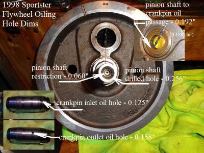 150)
150)
Oil System Modifications and Trade-Offs
1986-1991 Oil Pressure Relief Valve
1986-1990 engines are suggested to take oil pressure readings at the plug between the tappets instead of oil pressure switch at the filter pad per the FSMs.
Oil pressure, when checked at the oil filter pad (pressure switch removed), will be 6-10 psi higher than when checked at the tappet plug at idle per FSMs.
The pressure relief valve on 86-90 engines (inside the oil filter pad) is set to open between 30-35 PSI.
With it closed, the majority of oil flow is forced into the pinion shaft to the crankpin, lower rod bearings and drained to the sump to be scavenged out.
With the relief valve open, due to orifice sizes, over 80% of feed oil is sent to the cam chest floor via the discharge hole from the relief valve.
At 30-35 PSI and with the relief valve open, the relief discharge will receive most of the oil that would have went to the crankpin.
According to orifice sizes (.060“ pinion shaft restriction, .270” discharge hole), the relief valve is 82% bigger than the pinion shaft orifice.
And technically, when it opens then system pressure is drastically lowered and it should close rather quickly (restoring system pressure).
It is spring loaded and relies in large on oil viscosity to open on cold startup when system pressure is high.
Static pressure is high on cold startup (high viscosity oil) and gradually lowers as the oil heats up and thins out the viscosity.
Problems can occur if the relief valve stays open after the pressure lowers below relief spring pressure.
This can be tested using a standard PSI gauge.
Modding the relief valve inoperative
There have been several reports on the XLForum of the relief valve found to be not closing when the pressure lowers.
This is thought to be due to debris getting caught in the valve / spring / mechanism causing the valve to stay open.
Or another school of thought being the spring becoming weak and opening sooner or intermittently.
A few mods were introduced on the XLF to block off the discharge hole from the relief valve, keeping the oil from discharging out of the feed path.
One idea has been to increase the spring size to a pressure where the valve couldn't open.
Another was to tap the discharge hole and block it off with a plug.
Either of these, done properly, will effectively block the discharge from happening.
So what is the trade-off of doing this mod?
Canceling the relief valve operation increases the amount of pressure (when generated by the pump) the pinion shaft / crankpin / lower rod bearings will see.
With the pinion shaft restricted orifice (.060“), the higher the pressure before the restriction, the more oil that can get aerated passing thru the orifice.
Pressure, viscosity and speed are factors in aeration here.
Any aerated oil in the pinion shaft is sent thru to the crankpin and out the lower end bearings.
Aerated oil does not dissipate heat as well as non aerated oil.
With this mod by default, the oil may not cool the lower end bearings as well (when the pressure exceeds what the relief valve would have removed, in excess of 30-35 PSI).
If aeration or froth gets high enough to the bearings, it will also not lubricate the bearings as well.
The bearing's operating lubrication regime is elastohydrodynamic and require a constant unbroken oil film to operate properly between the rollers and races.
In performing this mod, a comprehension of oil temp at the lower rod bearings would be nice to have, although impossible to achieve.
The oil directly under each roller within the bearing heats up in the center of oil film while being compressed between the race / crankpin.
Then that oil falls to the sump mixing with whatever oil temp is there. So oil temp from the rod bearings is altered before scavenging to the pump / tank.

