Table of Contents
This is an old revision of the document!

REF: Service Procedures 26
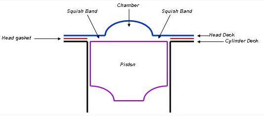
Squish Band
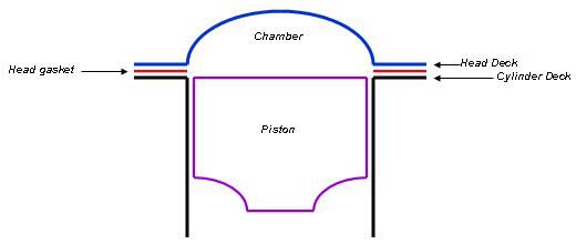
The squish (AKA “quench”) band refers to the area or areas,
where the piston comes very close to the cylinder head while passing through top dead center (TDC). 1)
 2)
2)
Even though the fire has already been lit, these areas still contain unburned air/fuel mix as the piston arrives.
The piston sandwiches the air/fuel up next to the head, causing it to “squish”, and shoot out toward the flame front.
The result is more chamber turbulence, better atomization of the fuel, and the squish band even has a cooling effect on the fuel.
They result in more complete combustion (more power and better fuel mileage) as well as better resistance to detonation.
The squish band clearance would normally probably be in the .040“ to .060” range from the factory.
But when you put it together yourself, you can take some extra time and effort and optimize certain things.
Ideally you'd like it more on the order of .030“ (or .035” if you're using a full cast iron cylinder).
You can optimize the squish band by adjusting the height of the cylinder head relative to the piston.
(such that the piston come closer to the head)
This will give you a little free power, better mileage, and more resistance to detonation.
If you let it get too close, you can actually get contact due to things like thermal expansion and piston rock.
When 883 heads are used over the larger 3-1/2“ 1200 bore or 3-9/16” bore 1250 cylinders, a squish band is gained around the perimeter of the chamber.
Measuring the Squish Band
Indirect Method
You can use a piston height gauge to measure how far above or below the cylinder deck the piston is sitting at TDC.
Then add that measurement to the gasket thickness.
This method works fine with both decks being flat.
But it doesn't work well with heads that have angled domes.
Direct Method
You'll be placing some soft material, such as .065“ solder, onto the squish band area of the piston.
(clay has been used for this also but it's not as accurate as using solder which won't change thickness)
Rotate the engine through TDC, remove the material, and measure it's thickness.
It takes more time than measuring the deck as in above because it requires an extra disassembly/reassembly cycle of the cylinder head.
But this method works great with flat or angled head surfaces. The tools required are no more than if you are installing the heads.
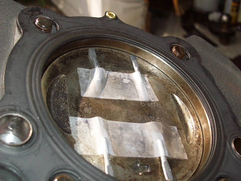
Place the solder in multiple places around the piston top.
Grease works best to hold the solder but if using tape, keep it below the squish band.
| Solder held with grease. 4) |
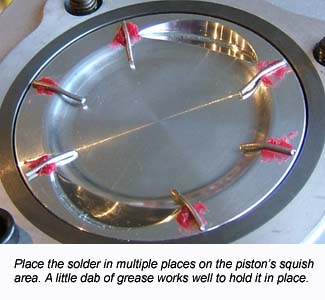 |
Install the head gaskets and heads then follow the torque procedure to full torque spec.
Next, remove the heads following the removal sequence in the FSM to keep from warping the heads.
| Remove the heads to reveal how far the solder was compressed. 5) | |
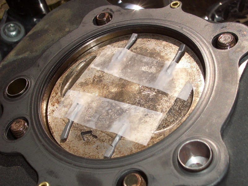 |  |
| Measure the compressed side of the solder pieces. 6) |
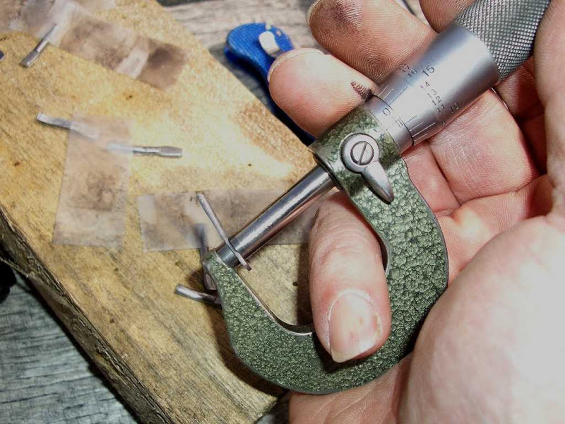 |
| Write the measurements down to conclude and average squish band dim. 7) | |
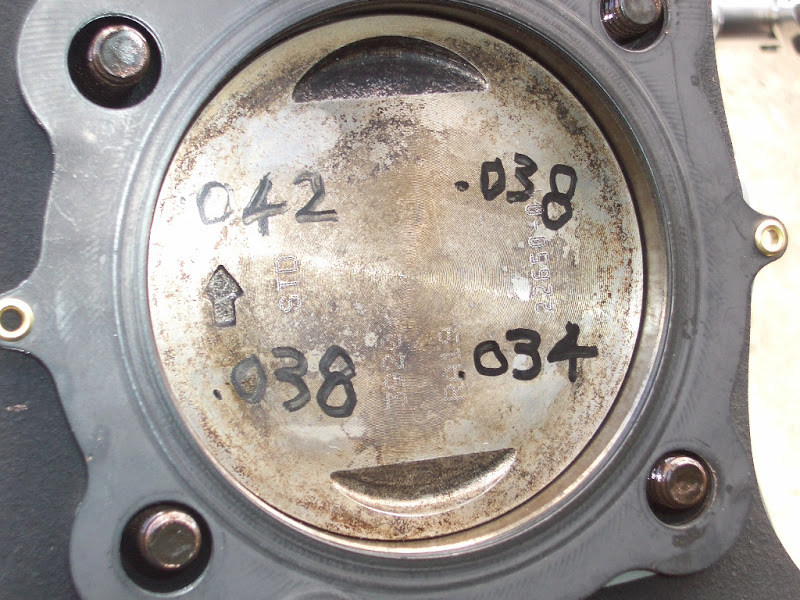 |  |
Gaining a Squish Band Due to a Conversion
Converting an 883:
An 883 head has a hemi chamber with no squish band but it's chamber is only 3” in diameter to match the 3“ bore size of the 883. 8)
What's fundamentally wrong with the hemi design is that it gives very poor chamber turbulence.
Poor chamber turbulence means poor air/fuel mixing, resulting in pockets of fuel.
It makes the chamber detonation prone. For this reason, all the hemi-chamber XL motors are & were limited to 9:1 compression.
(all 883's, and 88-03 1200's that is except 1200S models which had Buell lightning heads and 10:1 compression)
However, when you do a conversion, a very good side effect is that you gain a squish band around the perimeter of the chamber.
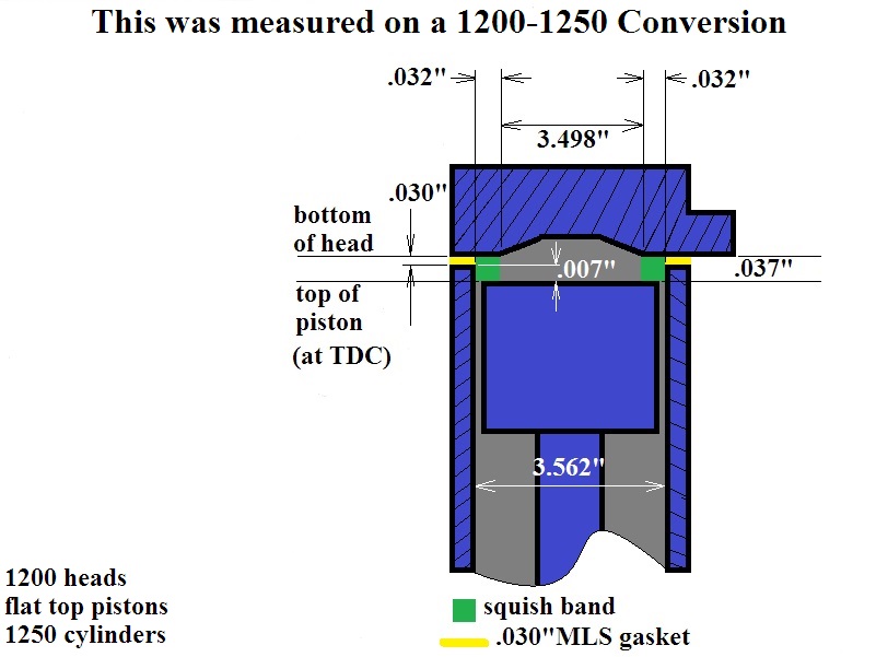
This is because you're now putting a 3-1/2” (1200) or 3-9/16“ (1250) diameter piston under that hemi chamber.
| 883 head on 883 cylinder (no squish). 9) | 883 head on 1200 or higher cylinder (squish gained) Also 1200 head on 1250 or higher cylinder w flat top pistons 10) |
 | |
Now with the squish band and as the piston passes through TDC,
Air & fuel that's trapped between the head and the piston in the “squish band” gets squeezed out.
(like stepping on a tube of toothpaste).
The result is more chamber turbulence resulting in better mixing, better efficiency, and less detonation.
In fact most people move to 10:1 compression when doing a conversion because the better chamber turbulence makes it possible.
Converting a 1200:
Machined Squish Band
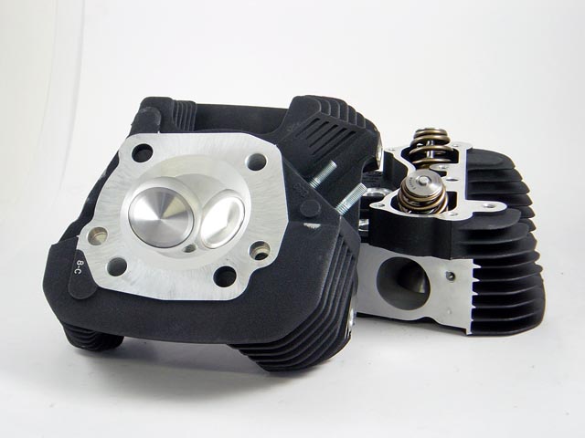
| Piston and head with matched squish band. 11) |
 |
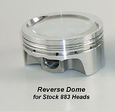
A piston with a reverse dome has a dish in the middle of it.
That dish is needed because when doing a conversion, you've got a chamber that's sized for an 883 and a piston that's sized for a 1200 or 1250.
That has the effect of greatly increasing compression ratio.
In order to make this combination work at 10:1, the piston needs a dish in the top of it as shown below.
Also notice how the piston has a shelf around it's perimeter that's about a quarter inch wide.
That's to meet the underside of the head and create the squish band.
The reverse dome conversion pistons below are a “bolt-in”, meaning they require no head work, they're made to work with stock 883 heads.
The squish surface area, as a percentage of the total area of the chamber, runs about 25%.
You'd like more on the order of 35% for optimum chamber turbulence.
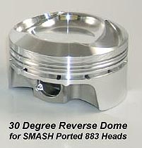
You can buy 30° reverse dome pistons and get the heads machined to match the piston angle.
Notice the head below has an angled dome all the way around it's perimeter.
This angle is fairly steep at 30° to match the 30° angled piston squish surface.
By making the dome real tall, you can end up with more squish band surface area than the standard dished conversion piston.
Tall domes are normally associated with high compression ratios, but the dish the middle of the piston is to get the CR back down to something streetable.
And removing material around the perimeter of the chamber reduces the shelf the air has to go around as it enters and exits the cylinder, improving breathing.
30° degree domes have been used in race bikes for forever.
But because the tall domes brought high compression ratios, this design was largely confined to race applications.
By dishing the middle of the piston deeply as shown below, the CR can be used on street bikes.
Deciding ahead of time on the performance upgrades you want is important.
When you prepare heads, the chamber wants to get bigger.
This happens for a variety of reasons.
The valves are sunk in the heads to gain (valve to valve) and (valve to piston) clearance.
As well as correct valvetrain geometry, and they're heavily unshrouded to improve low lift flow.
As in the head picture above, all these things increase chamber volume and makes the compression ratio lower.
At the same time, moving up the power scale really calls for more compression, not less, as the cams you'll use bleed off more compression.
You can deck the heads to drop the chamber volume somewhat, but that has limitations and bad side effects.
However, the coarse adjustment for the CR needs to be the piston and head decking should only be used for fine adjustments.
Therefore, if you do your conversion with the standard dished conversion pistons, you put some constraints on future performance work.
You're simply not going to be able to run as much cam or do as much head work so long as those standard conversion pistons are in your motor.
Check with your engine builder / supplier for further assistance if you're looking for a complete performance package.