Table of Contents
This is an old revision of the document!

REF: Tools - 133
Pinion Gear, Pinion Shaft Runout Tools
Pinion Gear
90 and Prior Models (4 Speed)
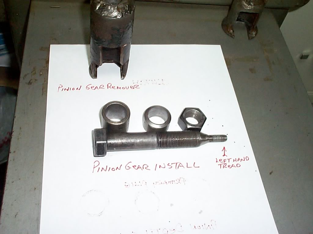 | 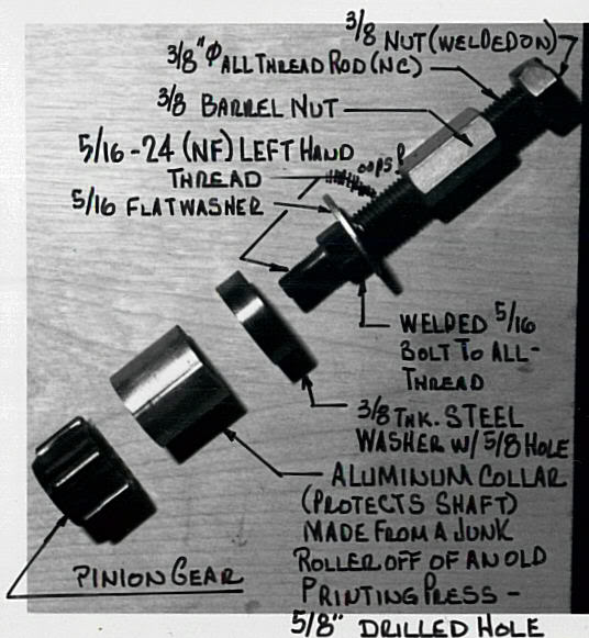 | 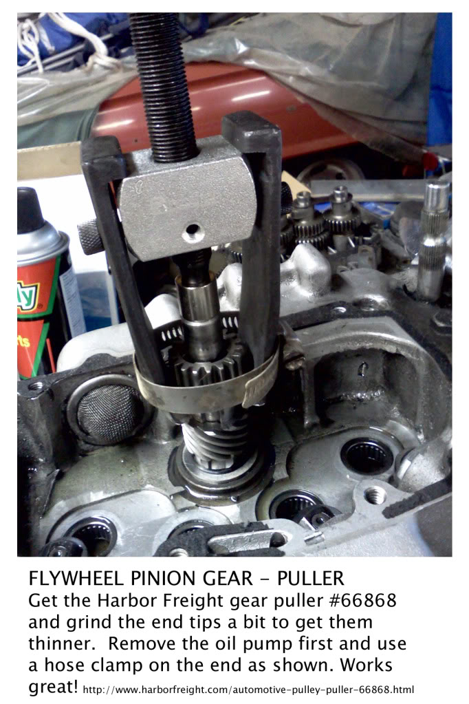 |
| Homemade Pinion Gear / Removal / Installation Tools 1) | Homemade pinion gear press 2) | Pinion Gear Puller 3) |
|---|
 | 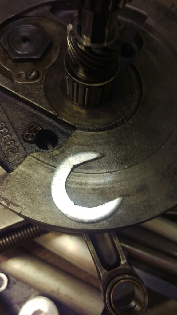 | 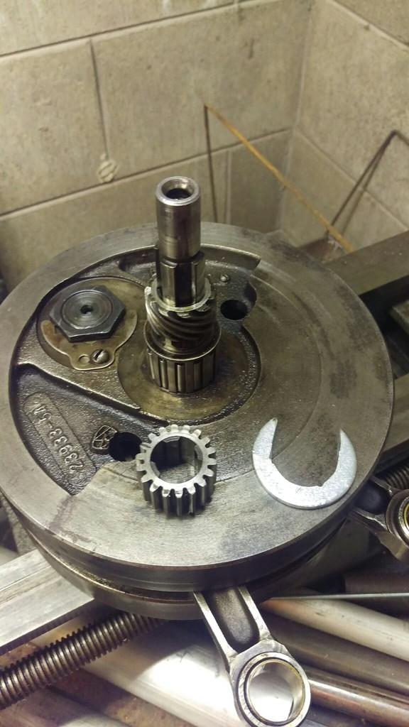 |
| Large fender washer cut into a “C” shape and a gear puller | ||
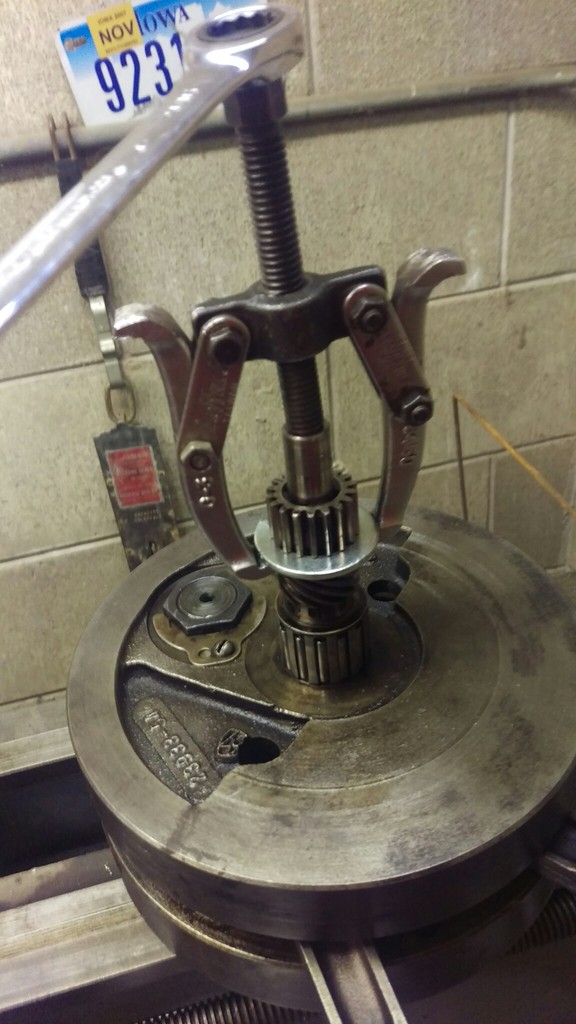
| Homemade Pinion Gear Puller 4) | ||
|---|---|---|
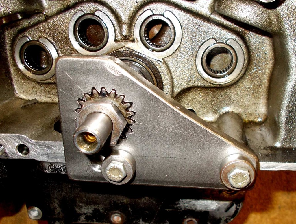 |
| 3/8“ stainless steel plate with 20° spokes (for 18 teeth), sawed initial groove to depth and widened it with files |
| Homemade pinion gear locking tool for '89 models 5) |
|---|
91 and Up Models (5 Speed)
For turning the engine over using the pinion gear nut
| You can use a 15/16” wrench or deep well socket to turn the engine over using the pinion gear nut. 6) | |
 |  |
| 93-Present Pinion Gear Nut (7916A) 7) | |
|---|---|
To remove or install the pinion gear nut
You'll need to lock the pinion gear from moving while turning the nut.
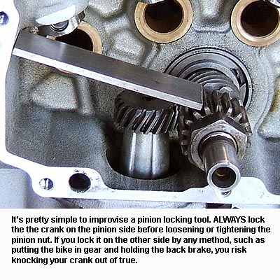
- It's very important to hold the crank on the pinion side with an appropriate pinion locking tool whenever you take the pinion nut off or put it on.If you hold the crank still from the primary side (or by putting the bike in gear and holding the brake), the twisting torque applied to the pinion nut gets transmitted through the crank, from one side to the other. The crank pin is not designed to resist much twisting force. You'll risk scissoring the crankshaft (knocking the crank out of true), which requires a full tear-down to fix. 8) So this is one of those situations where it's best to use the proper tool. 9)
| The Grindlock Pinion Shaft Locking Tool engages for the full depth of the pinion gear for max. strength. 10) Due to a change in the pinion gear in 2000, there are 2 different versions of this tool: 1. (91-99) year models & 2. (2000 to present) year models 11) |
|
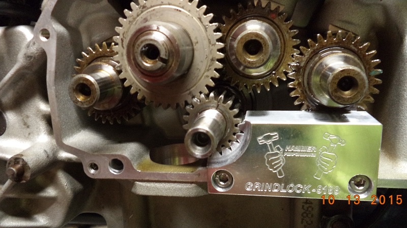 | 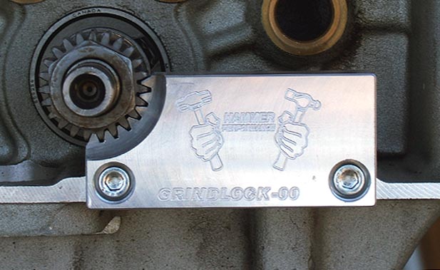 |
| Grindlock Tool (designed by XLFORUM member, “Grind”). 12) 13) |
|
|---|---|
 |
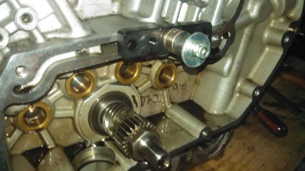
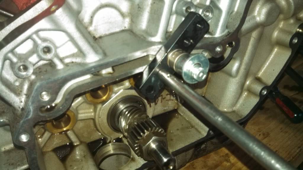
| Pinion lock made out of scrap steel 14) |
|---|
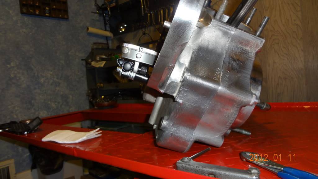
Pinion Gear Runout
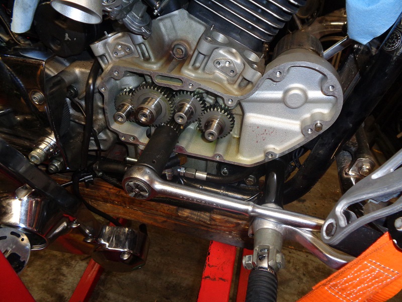
| Attach a scrap piece of metal to the outside of the gearcase and position a gauge holder on it so it won't move while turning over the engine. 15) | ||
 |  |  |
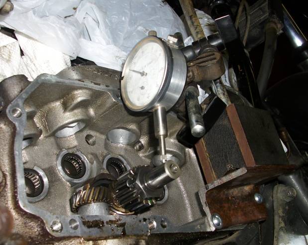
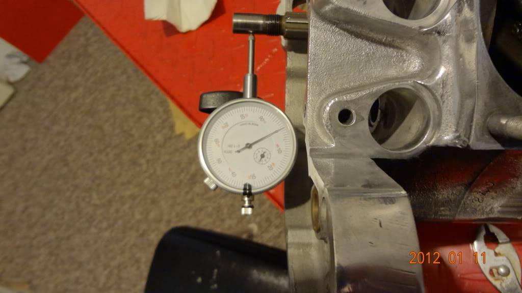
| Install a dial gauge on the holder with the pointer on the pinion shaft. Find the lowest spot while turning the engine over and 'zero' the indicator. 16) | This setup is made with a piece of angle iron for the magnetic base to stand on 17) | |
 |  | 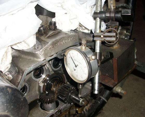 |
| This gauge post is threaded into a cover mount hole. 18) | |
 |  |
1)
photo by bustert of the XLFORUM http://xlforum.net/forums/showthread.php?t=395586&page=5
2)
photo by piniongear of the XLFORUM http://xlforum.net/forums/showthread.php?t=395586&page=12
3)
photo by 75bike of the XLFORUM http://xlforum.net/forums/showthread.php?t=395586&page=13
4)
photo by sevenyears of famine of the XLFORUM http://xlforum.net/forums/showthread.php?t=1888378&highlight=pinion+gear+tool&page=10
5)
photo by Big Al of the XLFORUM http://xlforum.net/forums/showthread.php?p=5322902#post5322902
7)
photo by Hippysmack
9)
aswracing of the XLFORUM http://xlforum.net/forums/showthread.php?t=2002257&highlight=pinion+locking+tool
12)
photo (L) by Hippysmack
13)
photo (R) by aswracing of the XLFORUM http://xlforum.net/forums/showthread.php?t=1920827&highlight=pinion+gear+locking+tool
14)
photo by aswracing of the XLFORUM http://xlforum.net/forums/showpost.php?p=3773793&postcount=2
15)
photos by anachris of the XLFORUM
16)
photo by Grind of the XLFORUM
17)
photos by dezzertrat of the XLFORUM http://xlforum.net/forums/showthread.php?t=1860581
18)
photos by DirtyCory of the XLFORUM http://xlforum.net/forums/showthread.php?t=1297584&page=8