Table of Contents

REF: Tools - 140
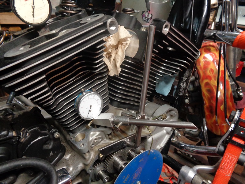
Tools for Dialing In (Degree-ing) Your Cams
The main components used for degreeing cams are a piston stop, degree wheel and a dial caliper.
 |  |
Getting the Right Dial Indicator
The dial indicator doesn't have to be expensive.
It just has to be accurate, placed properly and to where the gauge body won't move.
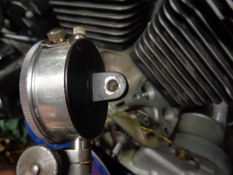
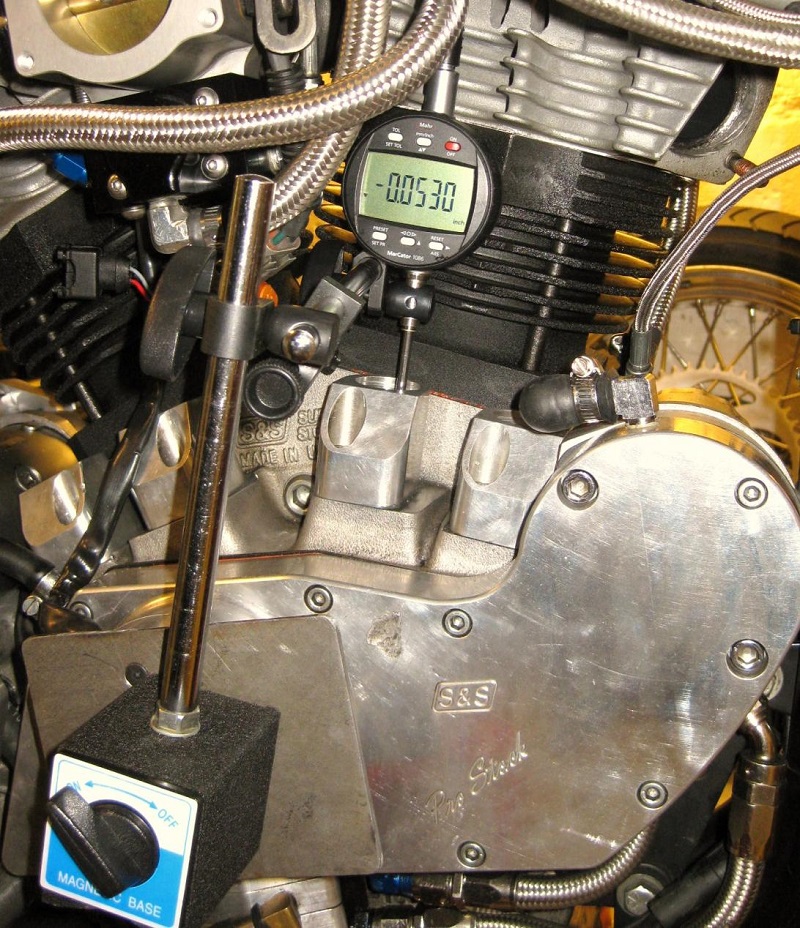
The indicator has to be held in place by the stem instead of the back cover to fit properly in the lifter hole.
There is no room between the cylinder and the lifter hole for a mount in the rear of the indicator.
See below how to temporarily change the backing plate on some indicators for this application.
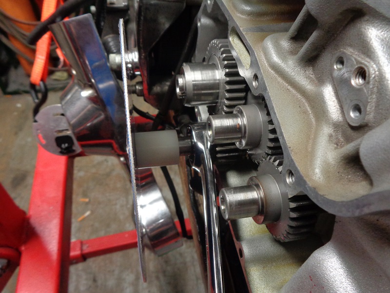
| An indicator with the post attachment on the back will not fit in the lifter hole vertically. 1) | Steel plate bolted against the gearcase cover for a magnetic base holder and digital indicator. 2) |
|
 | 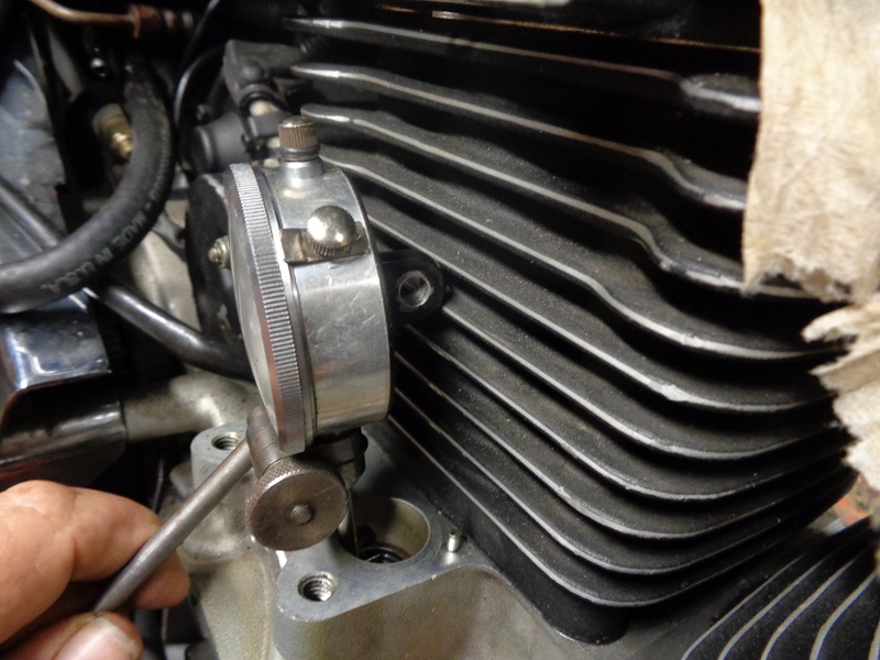 |  |
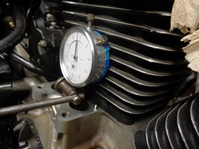
The probe on the indicator has to be vertical to and inline with the lifter (or cam lobe) to give accurate readings.
Also to keep from bending the probe as the lifter rises.
It can be placed in the center or on the outside lip of the lifter.
It also has to have enough travel of the probe so it won't bottom out before you get the measurements you need.
The cam lobe will probably have more than a 1/4“ so an indicator with only that much lift will not work.
A 1/2” probe travel will work;
But, you have to zero the dial before installing it to make sure you give the cam enough initial travel room.
An indicator with a 1“ travel works good.
You can set it down on the lifter 1 or 2 tenths, zero the dial from there and still have plenty of travel left for testing.
It gives more flexibility in setup.
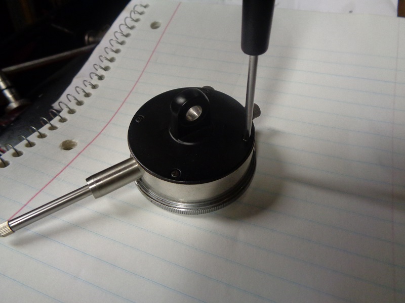
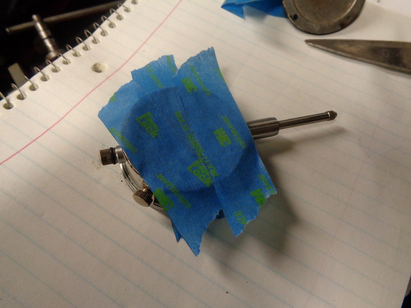
Temporary Indicator Backing Plate Mod
For dial indicators with the mount on the back cover, you can replace the cover with tape to allow more room between the indicator and the cylinders.
| You can take the back off, tape it off to keep dirt out and use a holder on the stem and it'll work fine. 3) | ||
 | 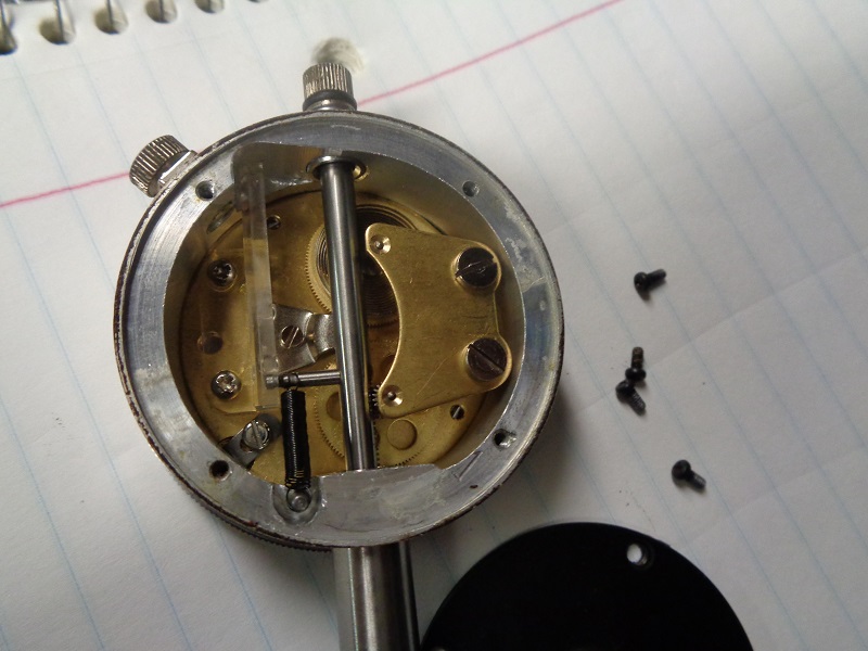 |  |
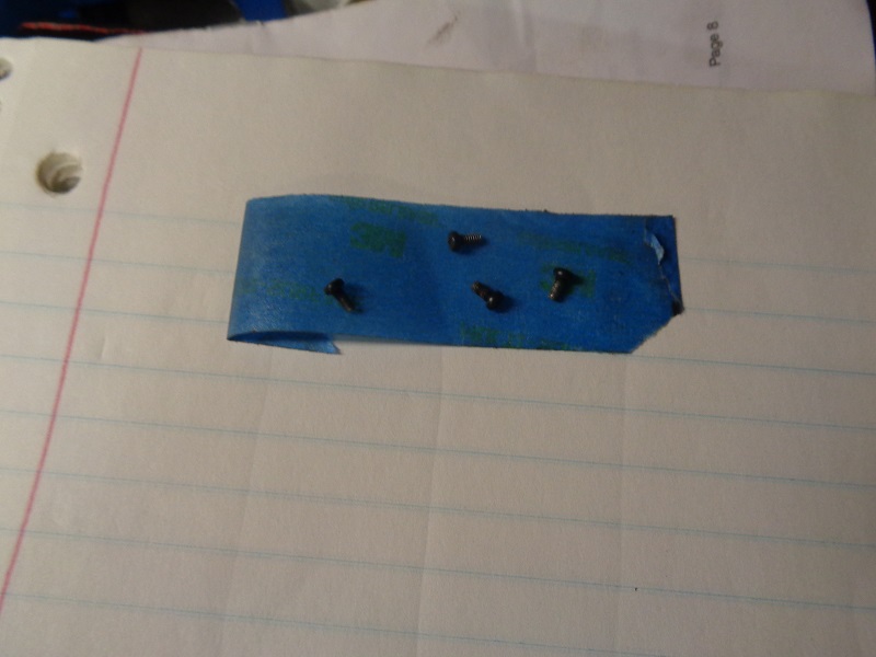
| You can place the screws in a piece of tape and store them for later. 4) | |
 | 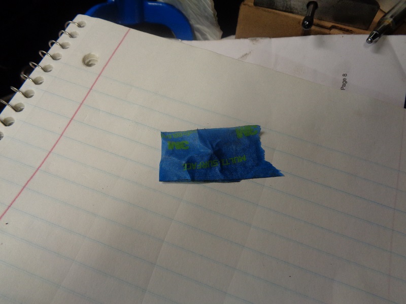 |
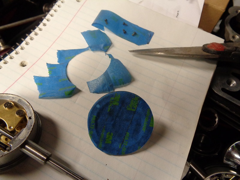
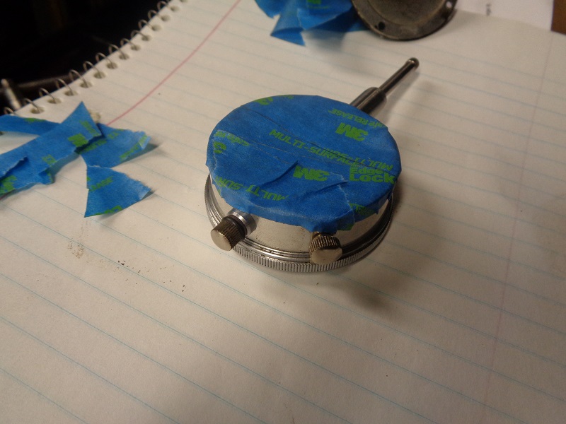
| Tape the inside of the cover, then cut around it. Remove the circle piece of tape from the cover, place the sticky side up on the back of the indicator. Then tape that down. This keeps the sticky side from getting stuck on internal moving parts. 5) |
||
 | 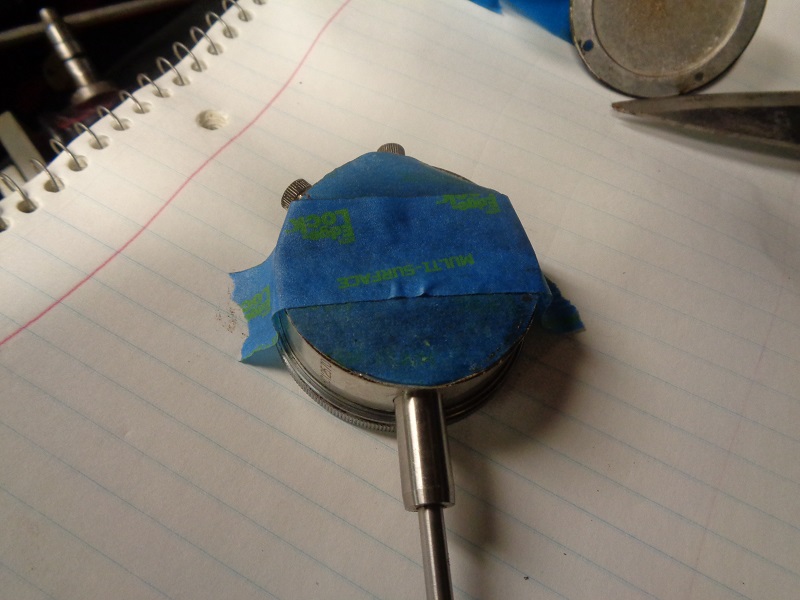 |  |
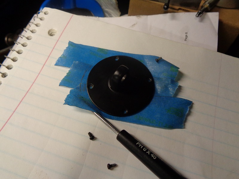
| Make sure to leave enough on the sides to hold down the temporary tape backing. Now this indicator can be used in the lifter hole. 6) |
|
 |  |
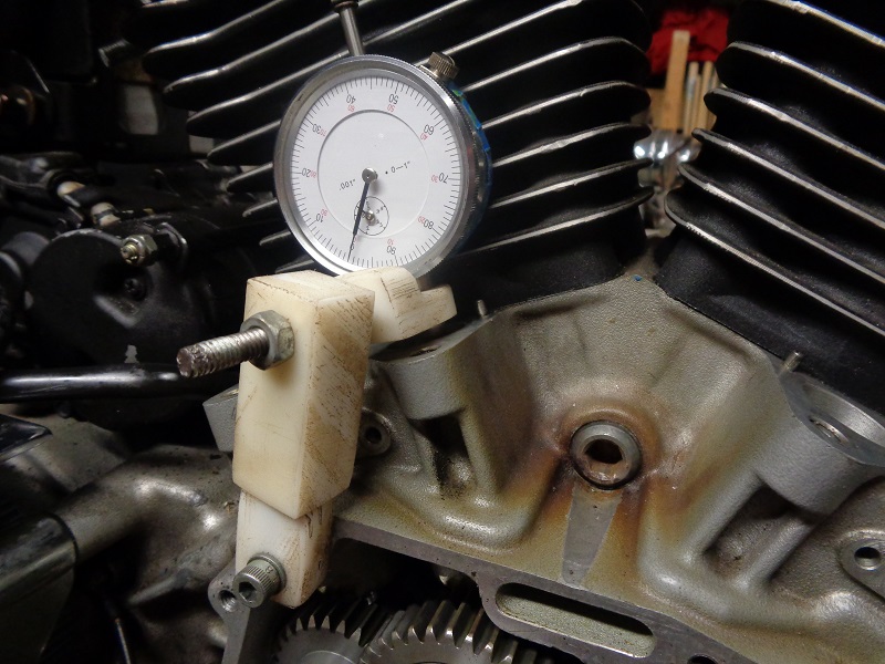
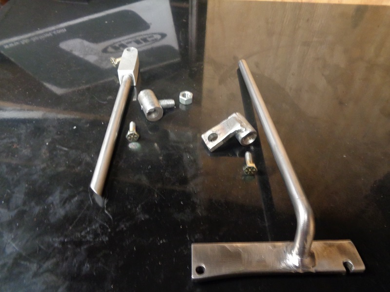
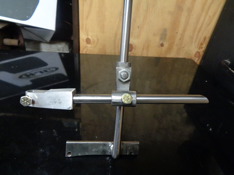
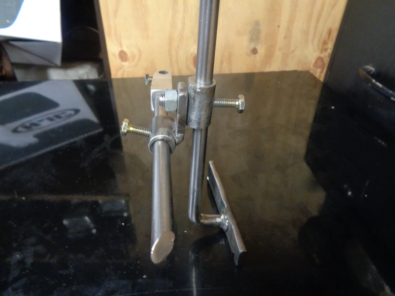
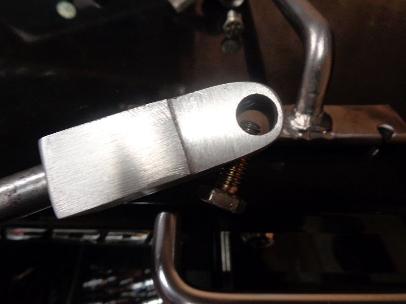
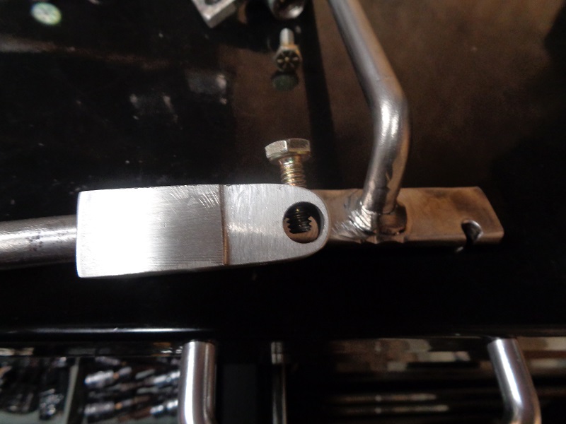
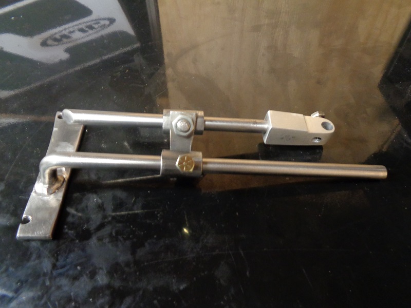
Tool Posts / Indicator Holders
| Homemade indicator holder from Nylon flat stock 7) |
|---|
 |
| Homemade indicator tool post from scrap steel and aluminum 8) |
|---|
 |
 |  |  |
 |  |  |
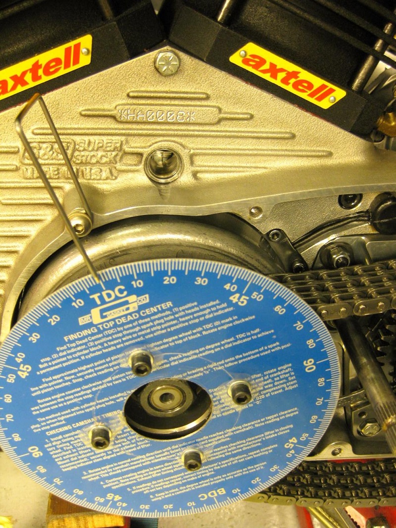
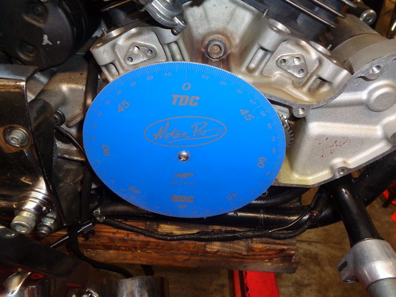
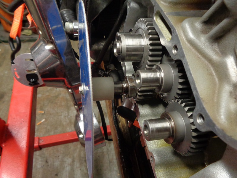
Installing a Degree Wheel on the Pinion Shaft
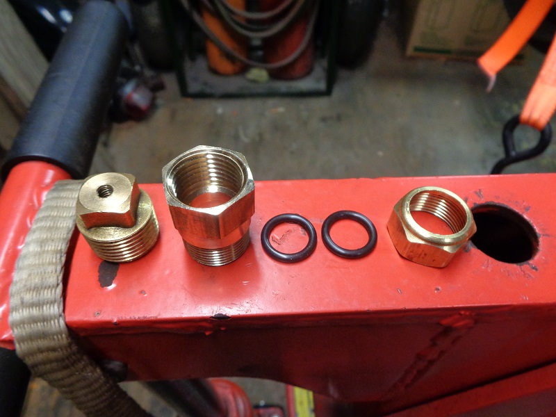
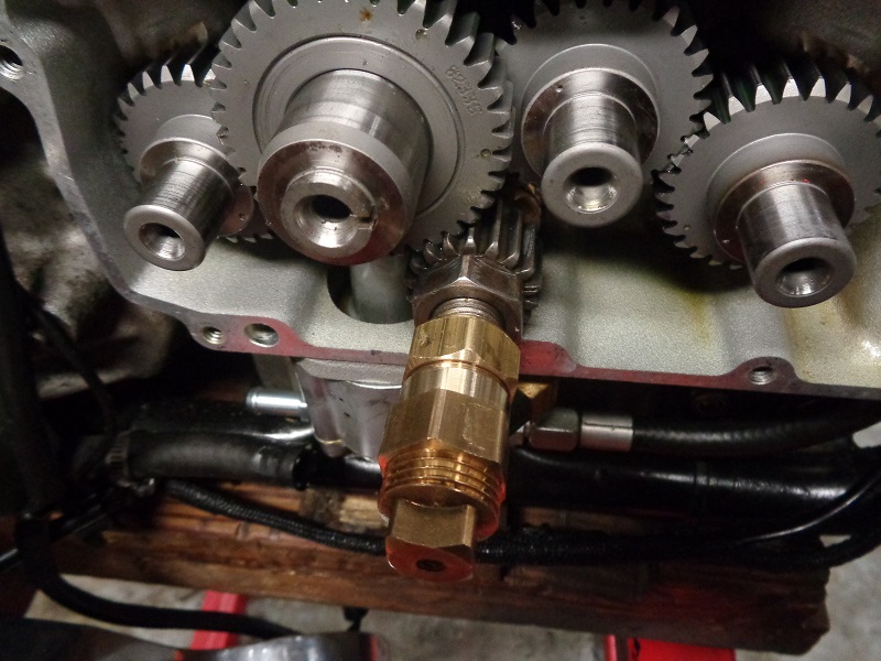
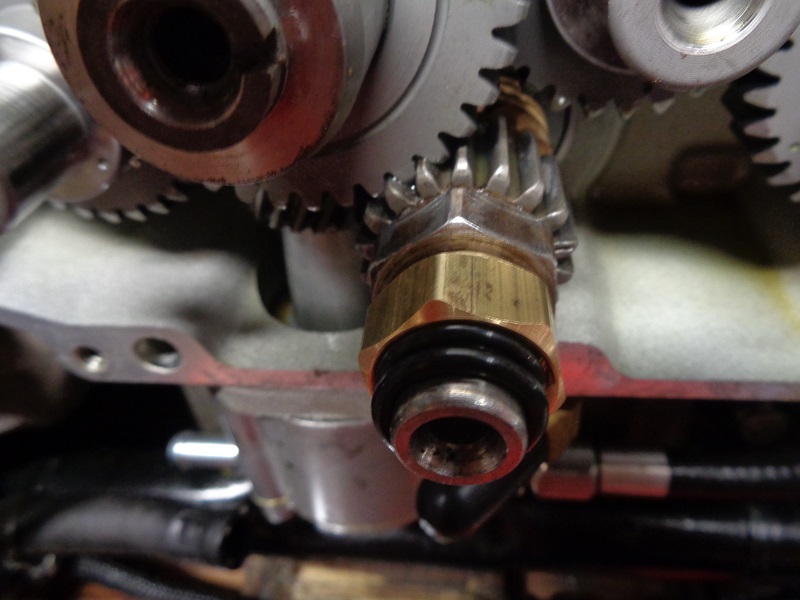
Brass Pipe Fitting
This fitting goes over the pinion shaft and holds tight with the use of two added O-rings at the compression end. 9)
- Parts (available at most plumbing stores):
- (1) 5/8” compression to 1/2“ FIP pipe fitting.
- (1) 1/2” pipe plug.
- (2) 11/16“ OD x 1/2” ID x 3/32“ O-rings.
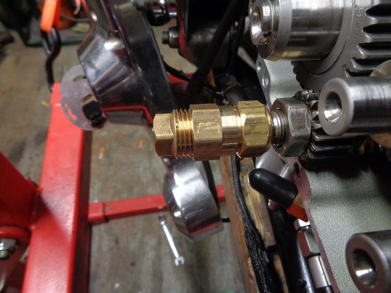
| Parts in assembly order | The assembled unit 10) | |
 |  |  |
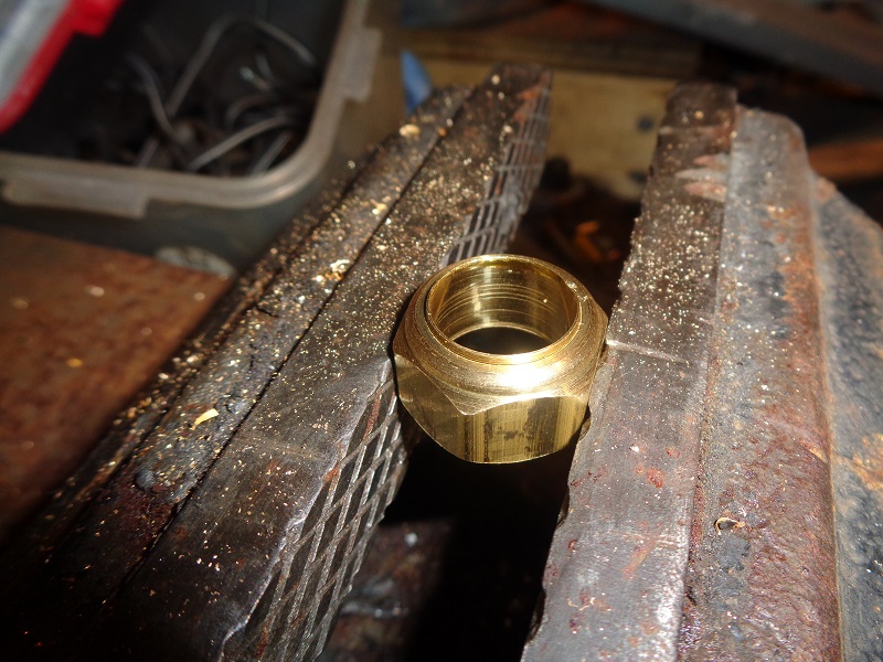
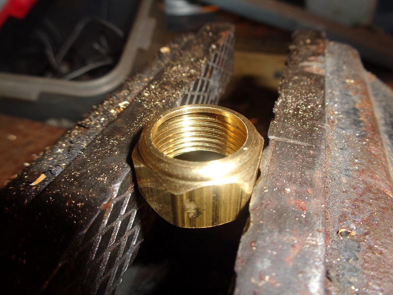
- Remove the ferrule from the compression nut.
- Install the nut over the pinion shaft.
- Next install the two O-rings onto the shaft (two will give a better response and lock up quicker). 11)
| First, remove the 5/8” compression nut and pop the ferrule insert out (not needed). | Install the compression nut followed by the (2) O-rings over the pinion shaft 12) |
|
 |  |  |
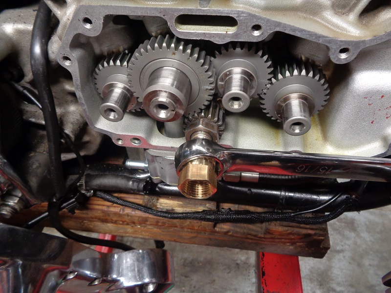
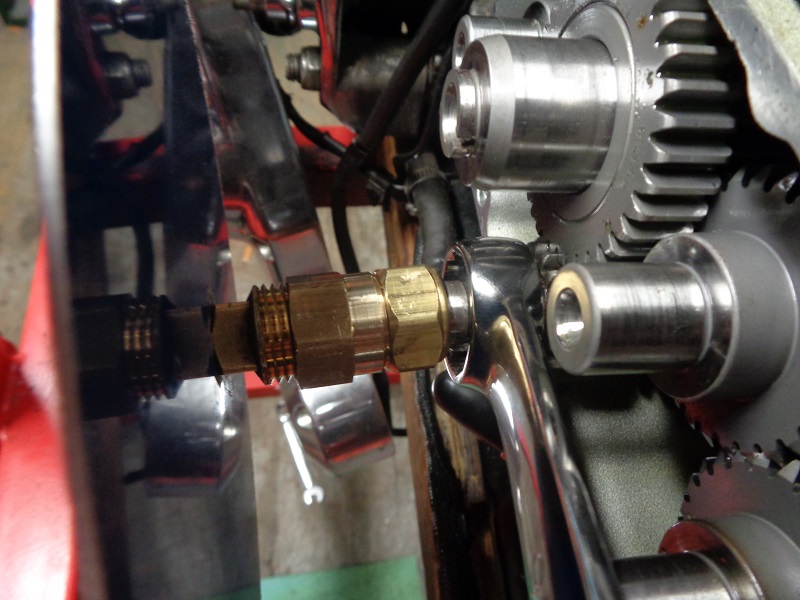
- The nut will pull up over the O-rings and then screw the FIP reducing nut onto the compression nut.
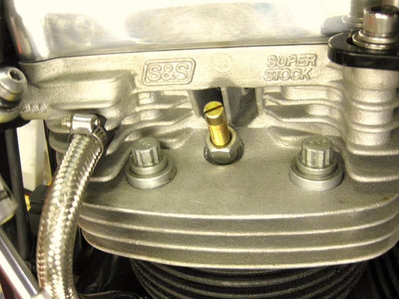
- Drill and tap the 1/2“ plug (#10-32 in this case to use the same screw that holds the timing cup to #2 cam) to attach the degree wheel.
- Bolt / screw the wheel onto the plug.
| A 15/16” box end wrench for the pinion nut will pass over the entire assembly before installing the wheel. | This way the box end wrench can be left on without falling off while turning the engine over with the pinion nut (tranny in gear or not). 13) |
|
 |  |  |
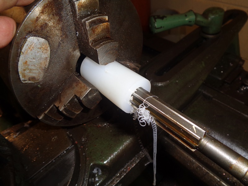
Nylon Bushing
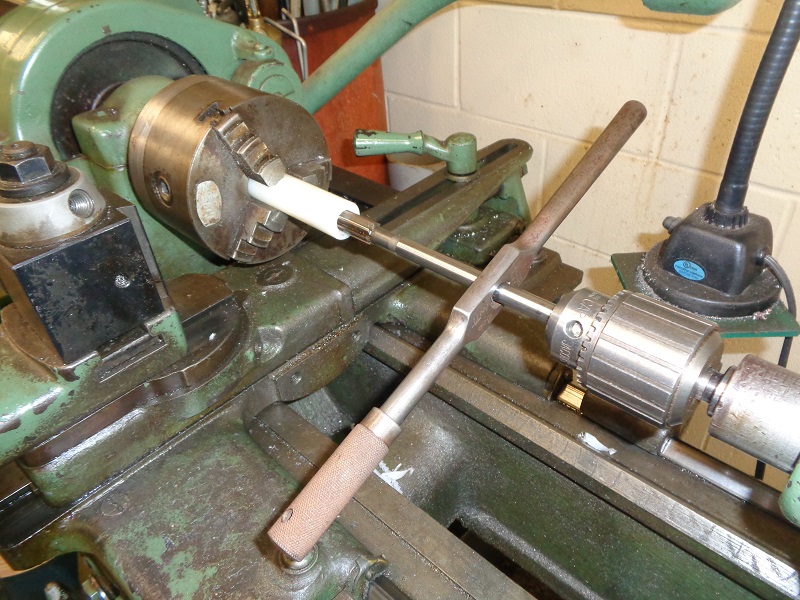
This nylon bushing was made using a lathe but it can be made in a drill press.
Nylon is easily machined but by nature it is vulnerable to heat.
Use thin cutting / lubing oil while drilling or reaming it.
Otherwise, the heat will melt and / or distort the hole your working with.
For this reason, it's probably best to hand ream instead of with a machine. 14)
 |
- Parts List:
- A piece of 1“ round stock of Nylon (app. 1” long).
- Tools:
- .5615“ Chucking Reamer (straight shank, straight flute).
- 35/64” drill bit (pre-drill for reamer and also several smaller sizes leading up to it).
- #10×32 tap
- #21 drill bit (pre-drill for tap)
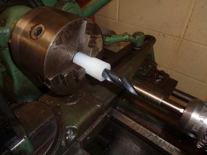
- The hole should be drilled with 2-3 stepped drill sizes and allowing the bushing to cool before each bigger size.
* Drilling with the final size pre-drill bit (first) will most likely end with the hole being too big to ream or to fit snug on the pinion shaft *
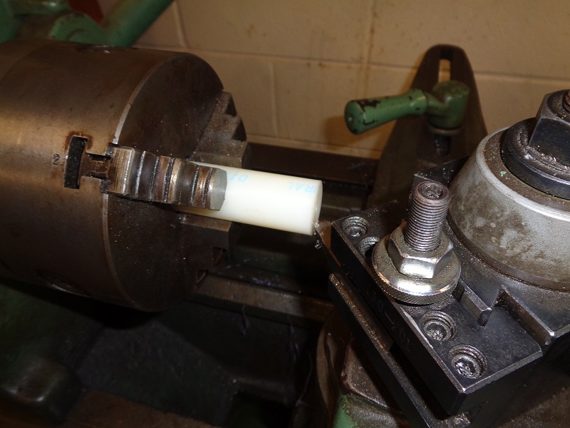
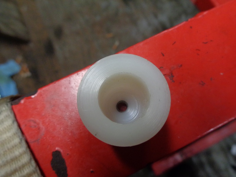
| Front faced and pre-drilled for a flat wheel mount. 15) | Piece turned 180° and pre-drilled. 16) | Final pre-drill with 35/64“ bit. 17) |
 |  |  |
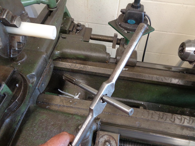
| This tap wrench has a “V” slot in the tightening mechanism to allow for use with round tooling. 18) | Reamer set in straight, “lightly” snugged into the chuck jaws enough to still spin by hand. Bushing is gently reamed by hand keeping down the heat. 19) | Bushing removed, cut to desired length and tapped for #10×32 threads. (same screw that holds the timing cup to #2 cam) 20) |
 |  | 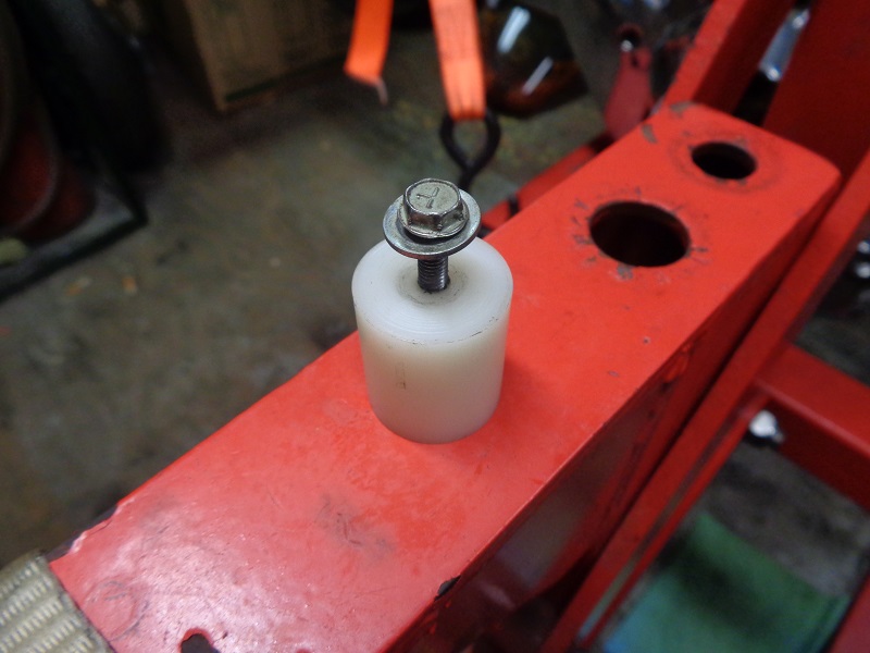 |
| If made carefully, there is no need for a set screw on the nylon bushing. It's either the slip fit, chamfer on the inside rear of the hole from the drill bit, trapped air when the bushing is installed, composition of the nylon or a combination of these things that holds the bushing firm when pushed onto the pinion shaft. 21) |
||
 |  |  |