Table of Contents
This is an old revision of the document!

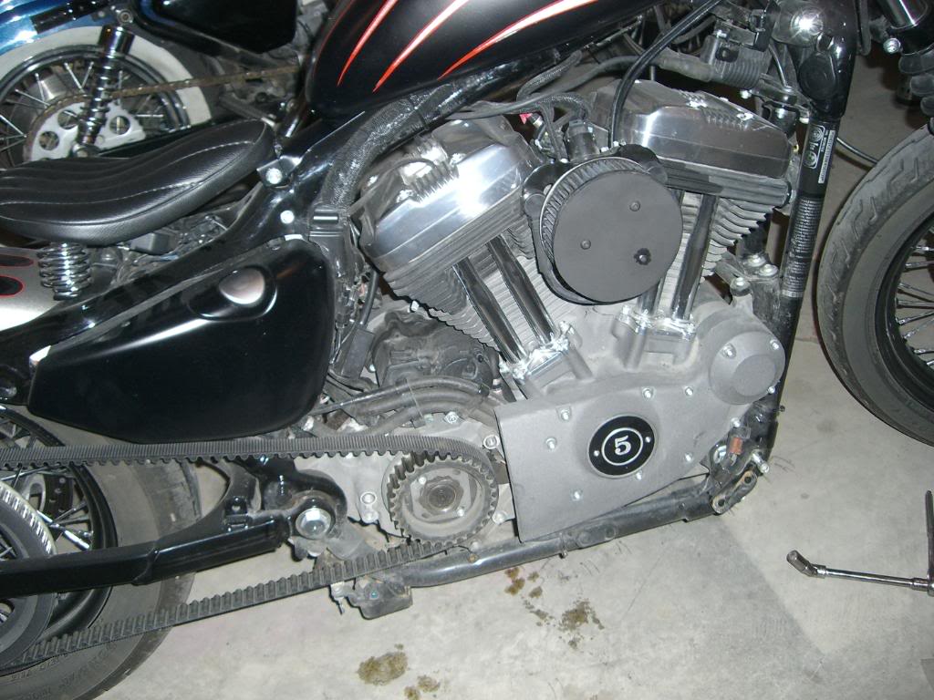
EVO: Engine Mechanicals
Timing Inspection Hole
Sub-Documents
Cam / Gearcase Cover
Removing the Cam Cover
- Checklist:
- You'll need to bleed down the lifters and loosen or remove the rocker boxes:
- Pulling the cover without first loosening the rocker boxes to take the pressure off is generally a bad idea.
It's hard on the cam bushings to have valve spring pressure pushing down on them while the cams are only supported on the inboard side. 1)
See the links above for removing the rocker boxes prior to removing the cam cover. - The rocker box puts downward pressure thru the pushrods / lifters to the cams and subsequently the cam bushings.
- The bushings are then pressed hard against the cover in which the bushings reside. Kinda like holding your arm down on a table and let someone push down on your arm.
Then try to pull your arm away. It's harder to do. - Without relieving that pressure, pulling the cover off can let the front of the camshafts fall down.
- This throws all that weight on the bushings inside the case that the other side of the camshafts are in.
- At this point, the camshafts are sitting in there at an angle waiting to tear into the bushings.
- This can destroy the bushings in the case.
- To bleed the lifters respectively on each cylinder:
- The first side, say the front, spin the engine around by rotating the tranny in high gear until you see both valves come up and back down.
- Pull the spark plugs.
- Rotate the engine through the intake cycle:
- Watch the pushrod end of the intake rocker arm as you're rotating the engine forward.
- You'll see the intake rocker move up and open the valve.
- Then you'll see the rocker lower and close the intake valve.
- When the intake valve closes during rotation, both valves will stay closed for a bit on further rotation.
- As long as you stop on a point where both valves are closed it's fine.
- That puts the lifters at there lowest point (on their base circle) and their least amount of pressure against the bushings.
- You can also have a helper watch for the TDC line to appear in the center of the timing hole with the plug removed (if applicable).
- Now, walk away for 20-30 minutes while the oil slowly gets pushed out of the lifters at this point.
- Then remove the lower rocker box on the front head.
- Next, repeat the above for the rear cylinder.
- You can remove the pushrods before removing the lower box so you don't have too pick it up over them.
- But either way, now the pressure is off the cam bushings and it's a lot easier and safer to remove the cover.
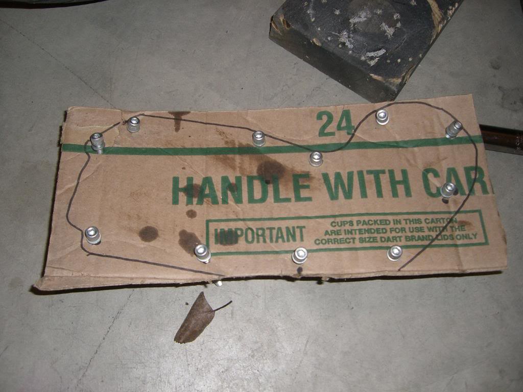
- The cam cover has 11 Allen head screws of various lengths. They will need to be replaced back in the same holes from which they were removed. So, their proper location will need to be marked upon removal. You can make a drawing of the cam gear case on a piece of cardboard and then put them into the cardboard in the proper orientation as removed from the cover. 2)
- Remove the Entire Rocker Box and Pushrods:
- Although it may not be necessary and depending on your foot control setup;
You may have to remove the foot peg / foot brake pedal support or brake rod to fully remove the exhaust or cam cover.
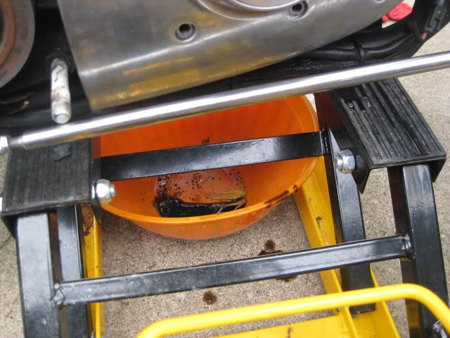
| Remove the exhaust. 3) | Place a flat drip pan or container under the engine to catch any oil leaking out. It will leak oil when the cover is removed. 4) | Remove the Allen screws holding the cover on and place them in holes cut into a piece of cardboard for safe keeping and sorting of various length screws. 5) |
 |  |  |
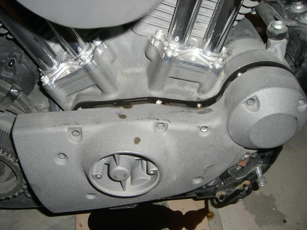
- Pull the cover out slightly so that it un-attaches itself from it’s gasket and the engine case.
- Note: The bushing alignment with the camshafts has a VERY close tolerance.
That means that the cover will need to come straight out.
There will be no side-to-side or up-down play in the cover.
- You may need to lightly tap the sides of the cover with a rubber mallet to break the seal between the case and the cover.
- Note: It's best to try and keep the cams in the gearcase while removing the cam cover.
- It's possible that the cams will stay in the engine when removing the cover.
However, more often than not, they will come out with the cover in various ways.
The alternative to not paying attention to them may end up with the cams hitting the floor.
Or worse, them hitting something on the way down causing damage to them. - Nicked journals will destroy the bushings, nicked lobes will destroy lifter rollers and both will create extra heat, destroying the cams and other internal parts.
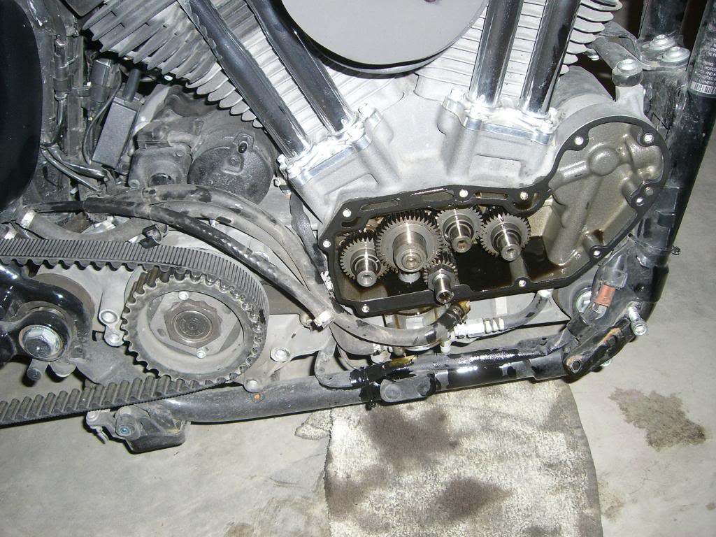
- With the cover out far enough to get a small screwdriver or putty knife between the cover and the case,
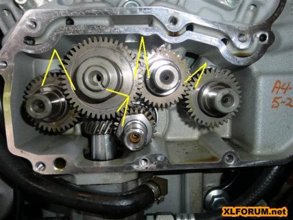
Continually push the cams back in towards the engine as you slowly edge the cover off starting with #2 cam. - #1 and #3 cams are behind #2 and will go back when you nudge #2.
- Don't forget about #4 which is independent and can come out on it's own.
- Once the cover bushings are clear of each cam, the case can be slightly rotated out of position.
- Also, you will need to remove a rubber oil line that attaches to the rear area of the case before the case can be completely removed.
Since the clamp holding this oil line cannot be reused, you will need to purchase a new hose clamp when the case is re-installed. - Remove and discard the gasket. Clean the case with brake cleaner.
| The cover should come off slow with even pull applied and all cams safely in the case. 6) | At this point, you can use a screwdriver or putty knife to push the cams back in the case 7) |
|
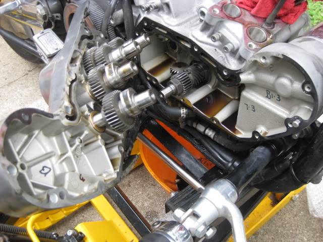
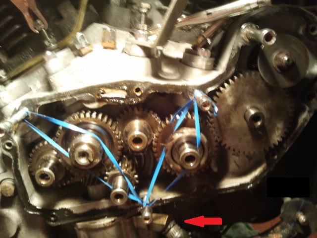
 |  |  |
| This is what happens if you don't remove the inspection cover and / or the rotor cup bolt from #2 cam before removing the cam cover. 8) | This is what can happen to the cams positioning if you try to re-install the cover with the cams still attached to it. 9) |
 |  |
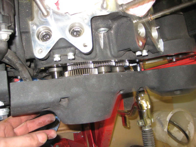
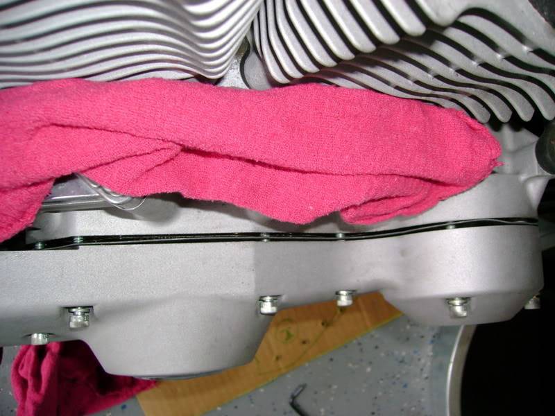
If you plan on leaving the cams in the case while working,
It's a good idea to secure the cams with string or rubber bands across #2 and #4 cams to keep them from falling out.
 |
| Securing cams with rubber bands 10) |
Installing the Cam Cover
The cover gasket only has a hole for one of the dowel pins so it will slip down if you're trying to place it on the case first.
Put the gasket on the cover and install the screws through the cover and the gasket holes while maneuvering the cover on the case.
Hand start all the screws and leave it loose enough to nudge the gasket, if needed, for a good fit.
This will keep the gasket from sliding down during the process.
Push it carefully the rest of the way on by hand. Do not use the screws to pull the cover flush against the case.
Engine Case / Sump Drain Plugs
 |
| Sump drain on 04 model 12) |
Pinion Shaft
Removing the pinion shaft nut
90 and Prior Models (4 Speed)
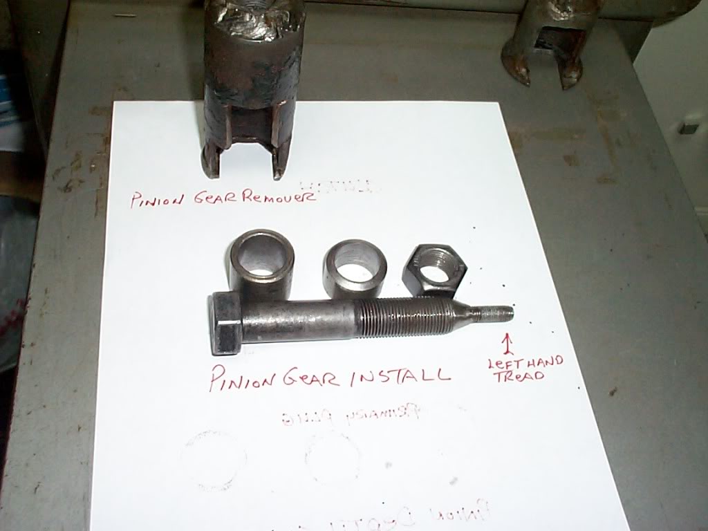 | 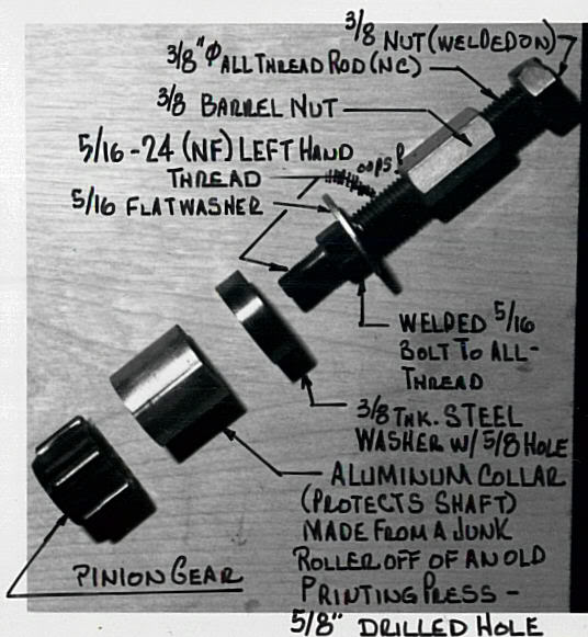 | 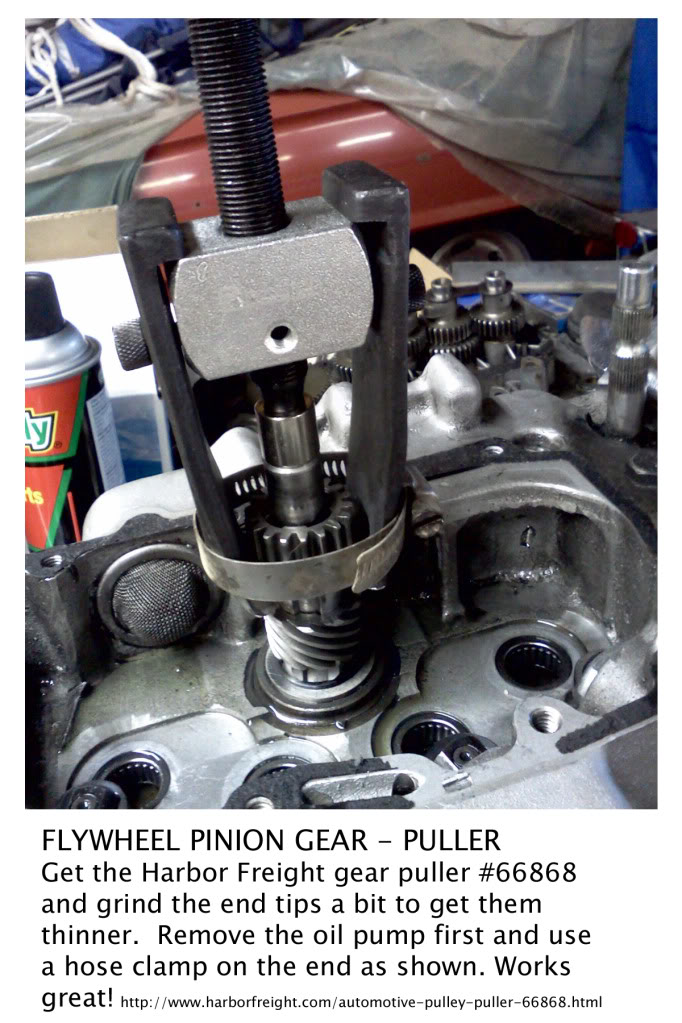 |
| Homemade Pinion Gear / Removal / Installation Tools 13) | Homemade pinion gear press 14) | Pinion Gear Puller 15) |
|---|
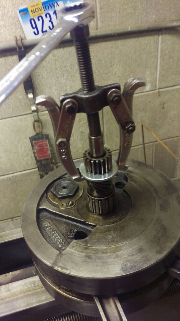 | 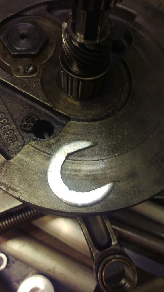 | 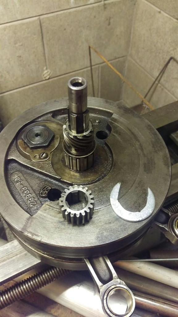 |
| Large fender washer cut into a “C” shape and a gear puller | ||
| Homemade Pinion Gear Puller 16) | ||
|---|---|---|
 |
| 3/8“ stainless steel plate with 20° spokes (for 18 teeth), sawed initial groove to depth and widened it with files |
| Homemade pinion gear locking tool for '89 models 17) |
|---|
91 and Up Models (5 Speed)
See also Oil Pump Drive Gear in the Evo section of the Sportsterpedia.
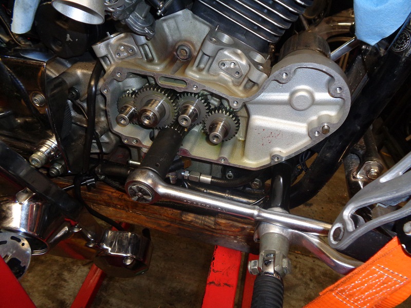
For turning the engine over using the pinion gear nut
| You can use a 15/16” wrench or deep well socket to turn the engine over using the pinion gear nut. 18) | |
 |  |
| 93-Present Pinion Gear Nut (7916A) 19) | |
|---|---|
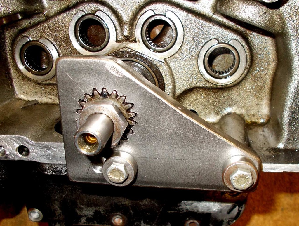
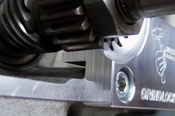
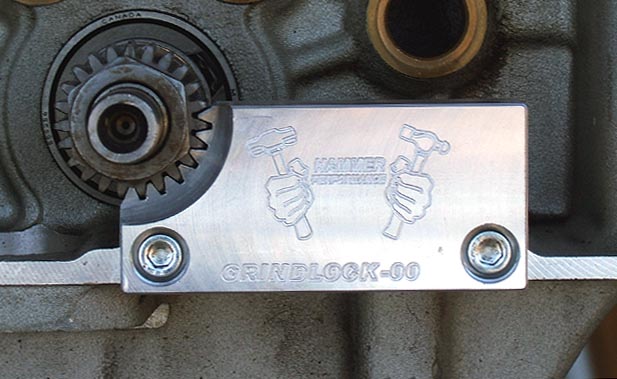
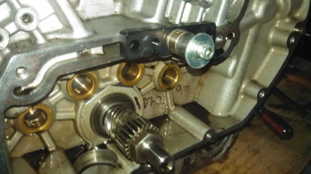
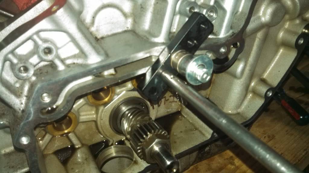
Read the Origin of the Grindlock Tool here
| The Grindlock Pinion Shaft Locking Tool engages for the full depth of the pinion gear for max. strength. 20) | Due to a change in the pinion gear in 2000, there are 2 different versions of this tool: 1. (91-99) year models & 2. (2000 to present) year models 21) |
|
 | 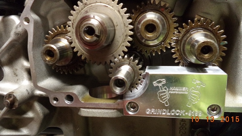 |  |
| Grindlock 91-99 & Grindlock 2000 (designed by XLFORUM member, “~Grind~” and Built by Hammer Performance 22). 23) 24) 25) |
||
|---|---|---|
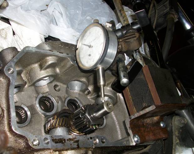
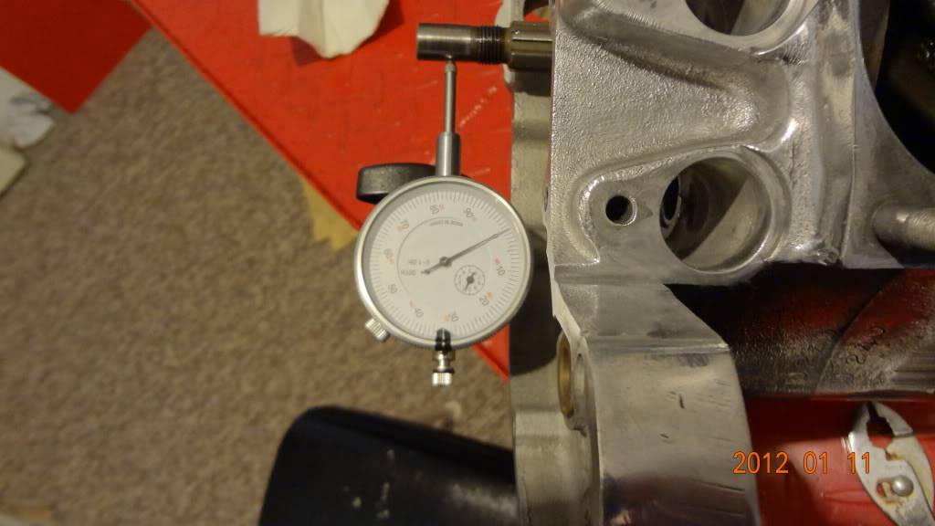
Pinion Gear Runout
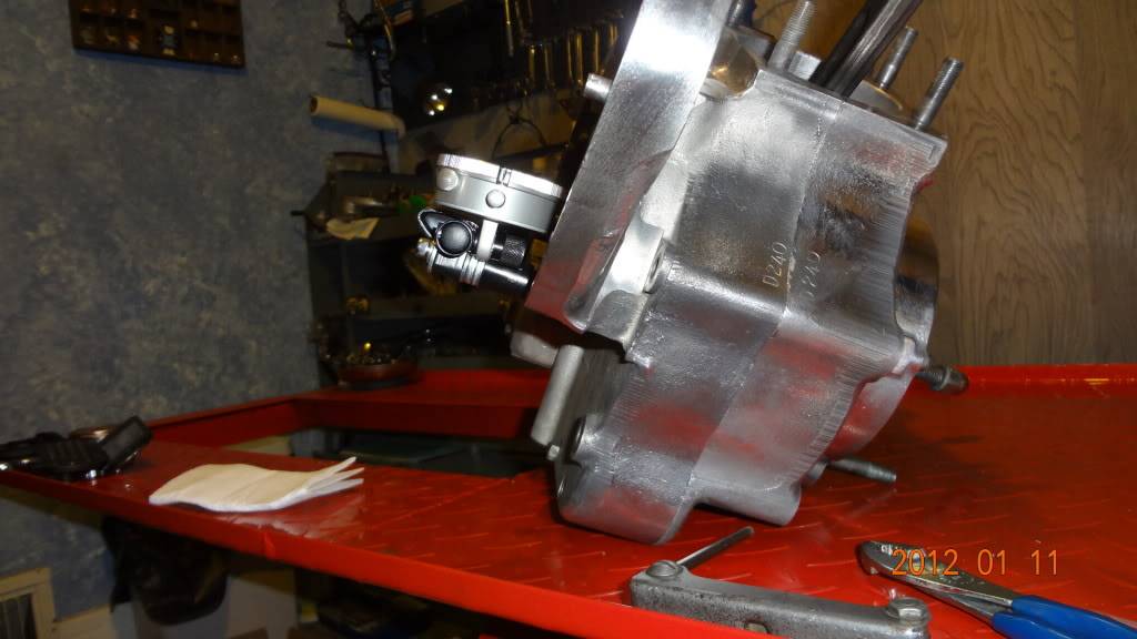
| Attach a scrap piece of metal to the outside of the gearcase and position a gauge holder on it so it won't move while turning over the engine. 26) | ||
 |  |  |
| Install a dial gauge on the holder with the pointer on the pinion shaft. Find the lowest spot while turning the engine over and 'zero' the indicator. 27) | This setup is made with a piece of angle iron for the magnetic base to stand on 28) | |
 |  | 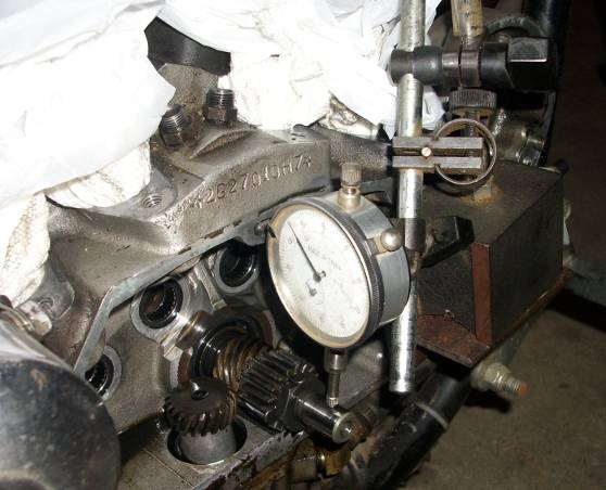 |
| This gauge post is threaded into a cover mount hole. 29) | |
 |  |
Once the pinion shaft nut is removed, the pinion gear may or may not slide off by itself.
You can use a gear puller to remove it if it is stuck on.
 30)
30)