Table of Contents
This is an old revision of the document!

EVO: Engine Mechanicals
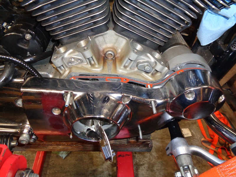
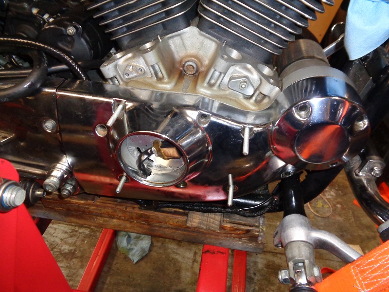
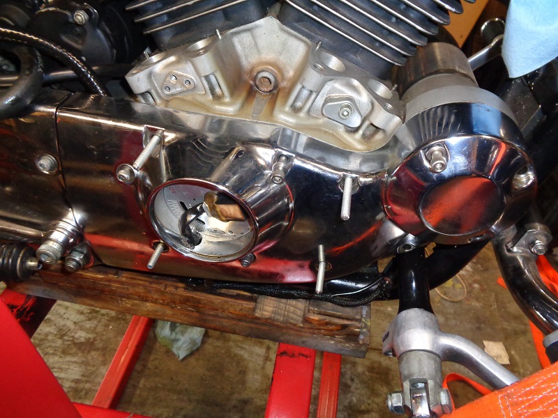
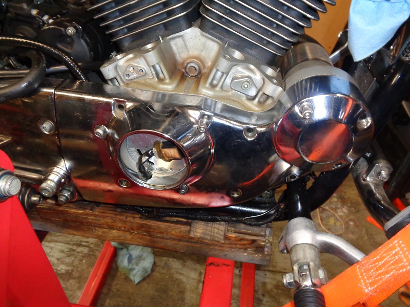
Timing Inspection Hole
Sub-Documents
Motor Mounts
Click here for Engine Mounts in the Evo Suspension section of the Sportsterpedia.
Cylinder Mounting Studs
| Weakest cylinder mounting stud holes in the case. 1) |
 |
Cam / Gearcase Cover
Sub Documents
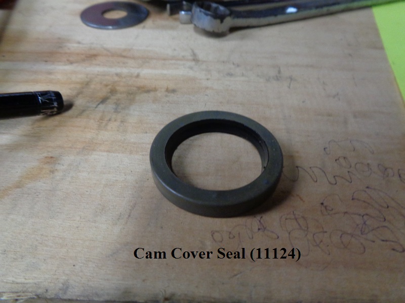
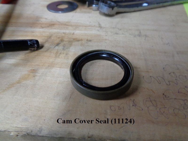
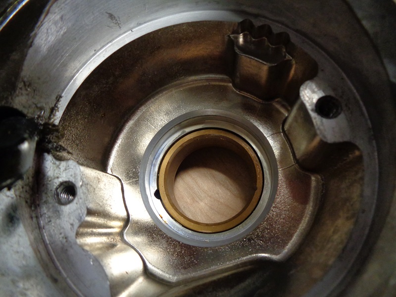
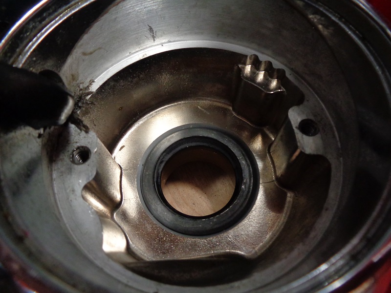
Cam Cover Seal
Seal number (11124):
This surrounds and seals #2 cam when the cover is installed.
 |  |
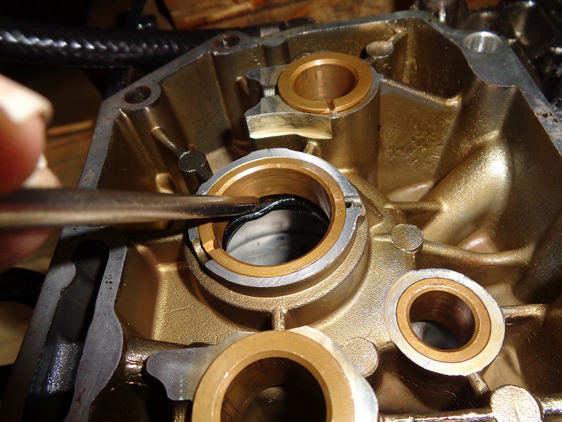
Removal / Installation
Using a screwdriver and hammer, insert the screwdriver inside the lip of the seal from the rear of the cover.
Knock the seal out of the cover. 2)
 | 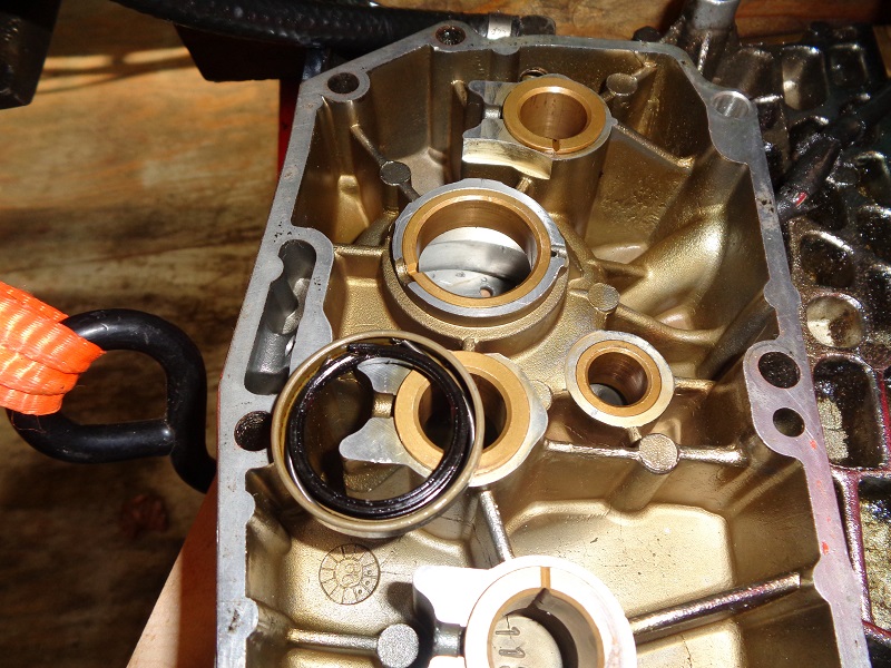 |
Clean the recessed area for the new seal thoroughly.
You can use compressed air or brake cleaner (cover the ignition if still installed).
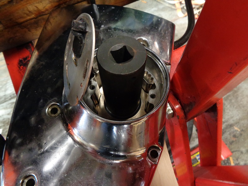
Set the new seal over the hole aligning it as straight as possible. 3)
 | 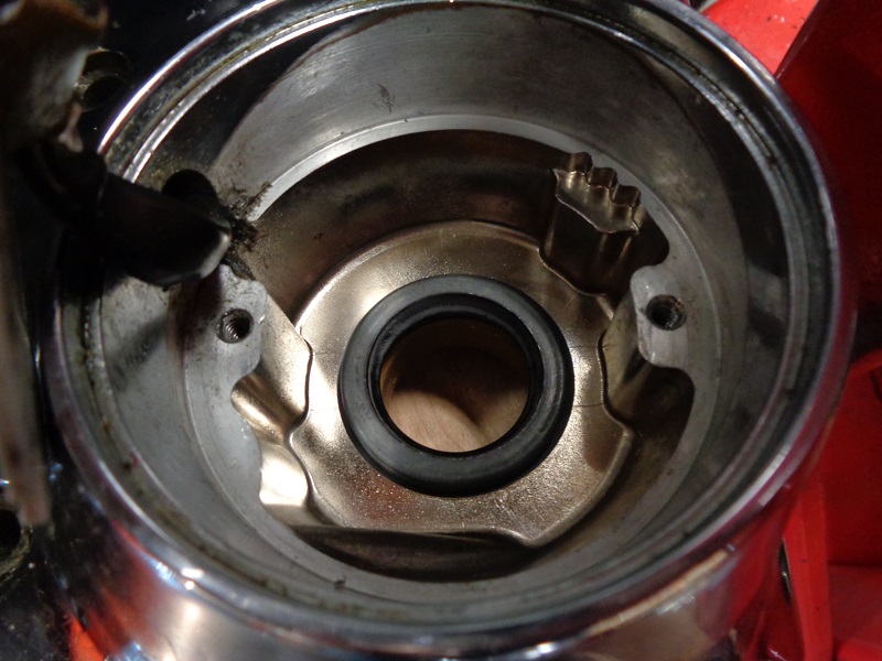 |
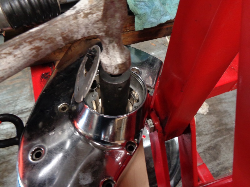
Use a socket and a hammer to drive in the new seal straight to the cover.
The socket O.D. needs to be just smaller than the seal.
Make sure the seal is flush to the cover when done. 4)
 |  |  |
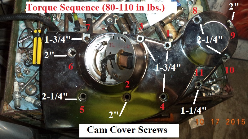
Installing the Cam Cover
The cover gasket only has a hole for one of the dowel pins so it will slip down if you're trying to place it on the case first.
Put the gasket on the cover and install the screws through the cover and the gasket holes while maneuvering the cover on the case.
Hand start all the screws and leave it loose enough to nudge the gasket, if needed, for a good fit.
This will keep the gasket from sliding down during the process.
Or you can use a few plastic straws inserted into the case threads and put the gasket on the case over the straws.
You can also buy a short piece of 1/4“x20 all-thread at the local hardware store and use it the same way as the straws.
The cover is app. 1-1/4” plus about 1/4“ of threading into the case would be 1-1/2” lengths just to get the shafts flush to the outside cover.
(which won't help you remove them.
So you'd need to cut off about four pieces at least 2“ long. 2” bolts with the heads cut off would also work.
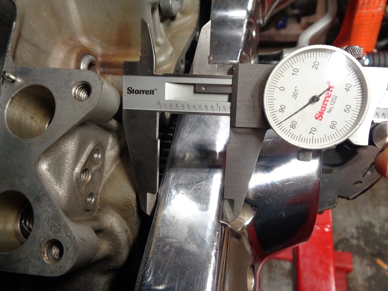
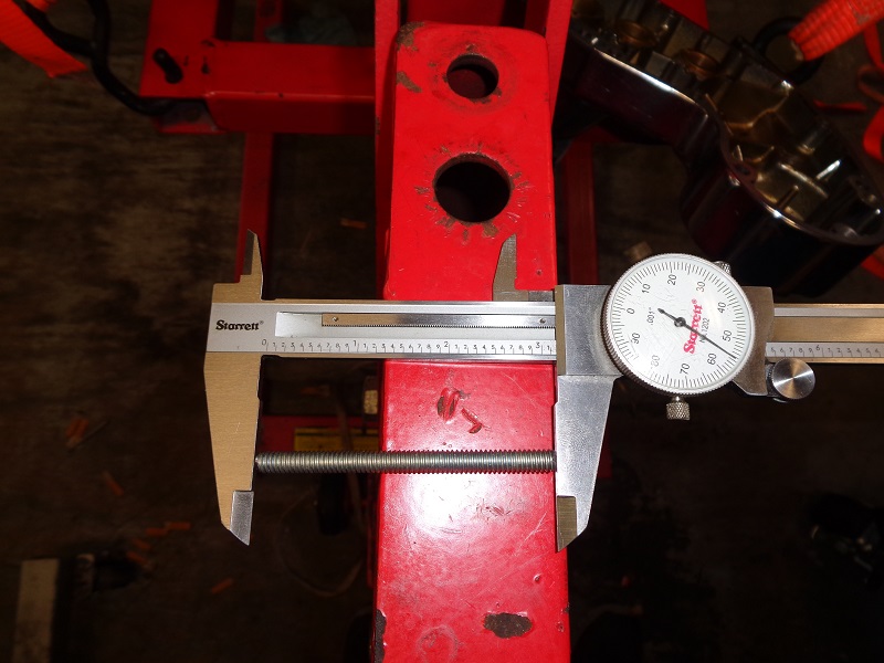
| These are app. 3“ long sections of all-thread. 5) | |
 |  |
| Install them into the case, hang the gasket on them and install the cover. The longer length pieces will allow you to center the cover bushings up to the cams easier for a straight push home. 6) |
||
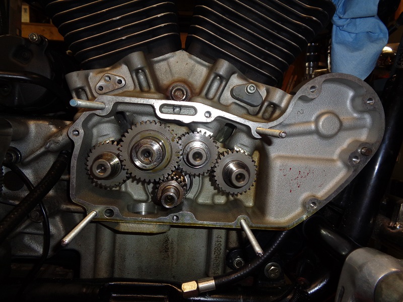 | 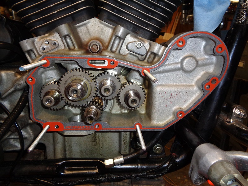 |  |
| Once the cover is on, install some 1/4” mounting bolts and pull the all-thread out. Then install the remaining bolts and torque to proper specs using a cross pattern. 7) |
||
 |  |  |
Primary Cover
Sub-Documents
Engine Case / Sump Drain Plugs
 |
| Sump drain on 04 model 10) |
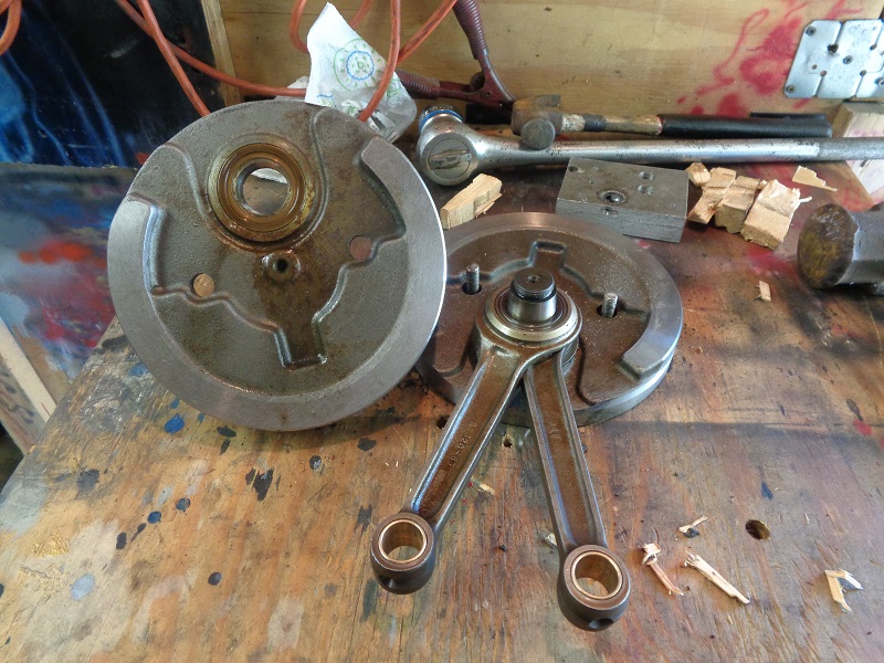
Crank Assembly
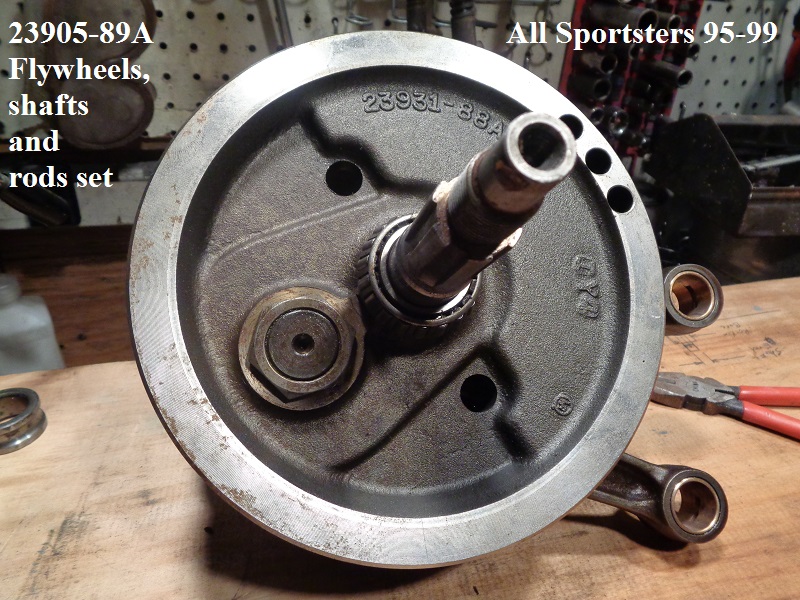
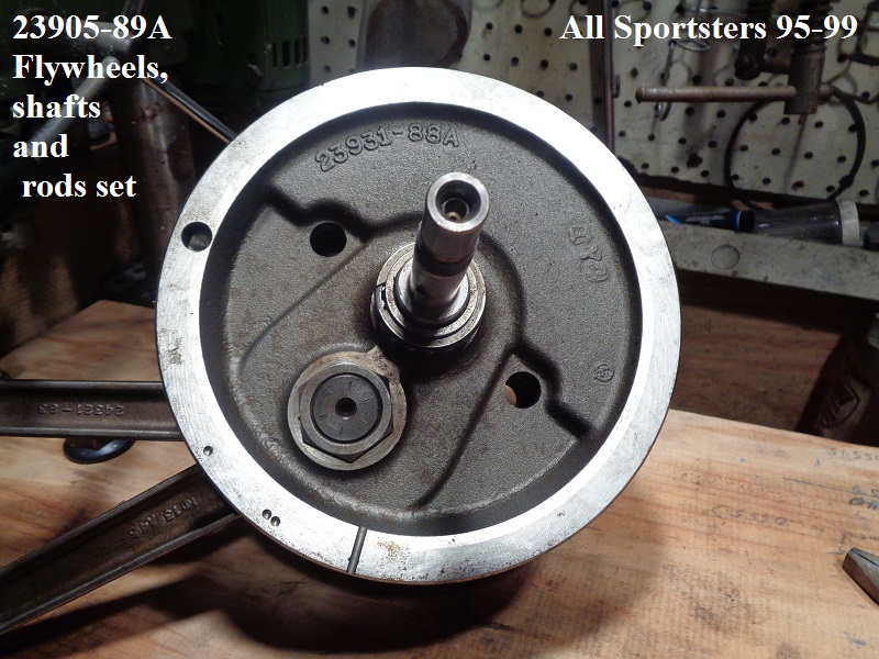
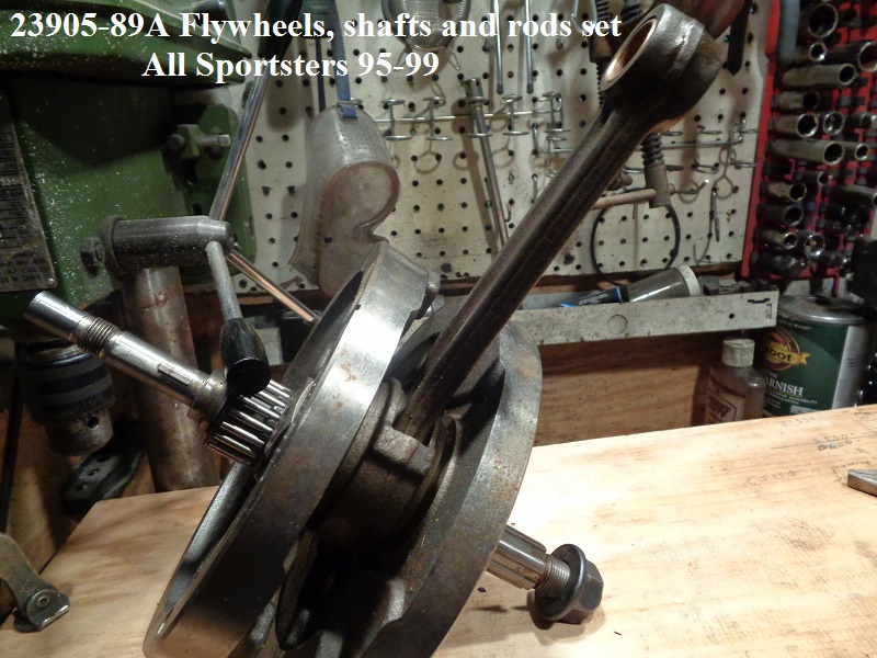
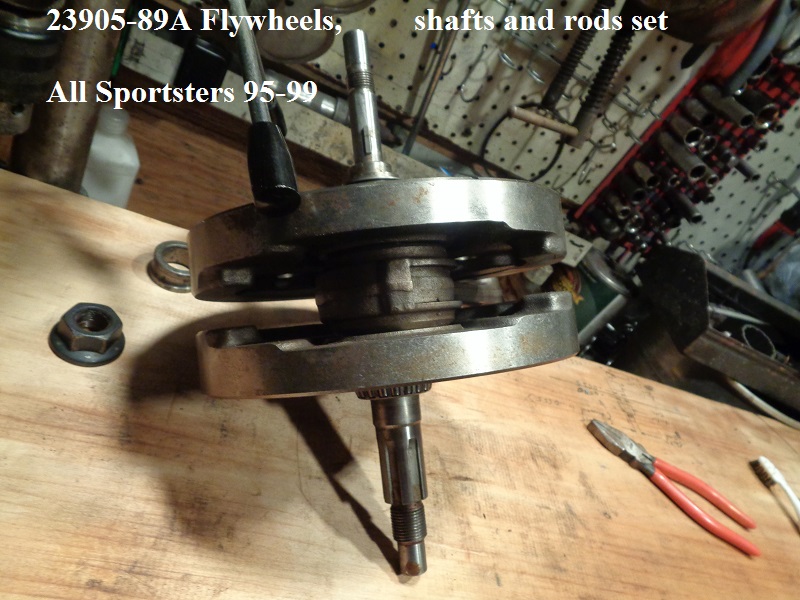
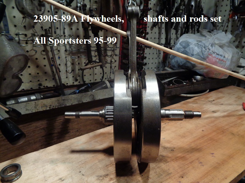
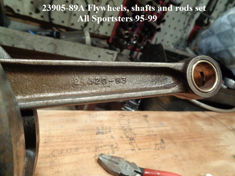
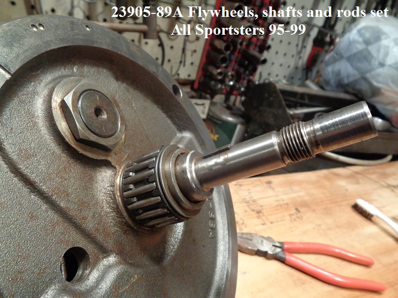
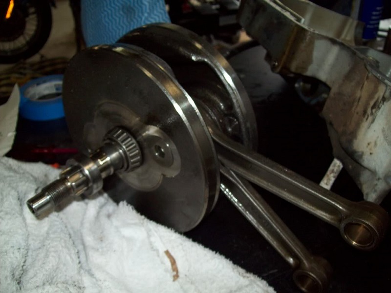
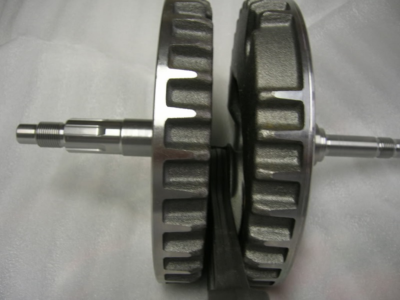
95-99
The same flywheel set was used in all Sportsters 95-99.
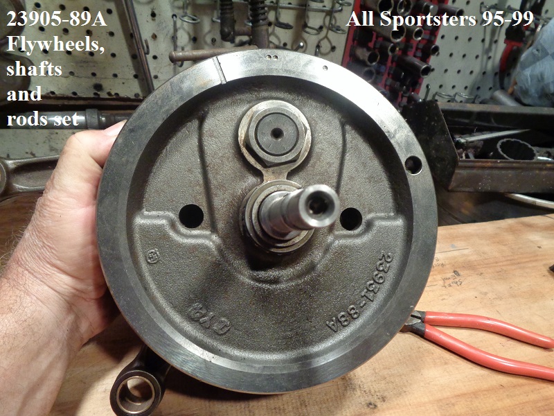
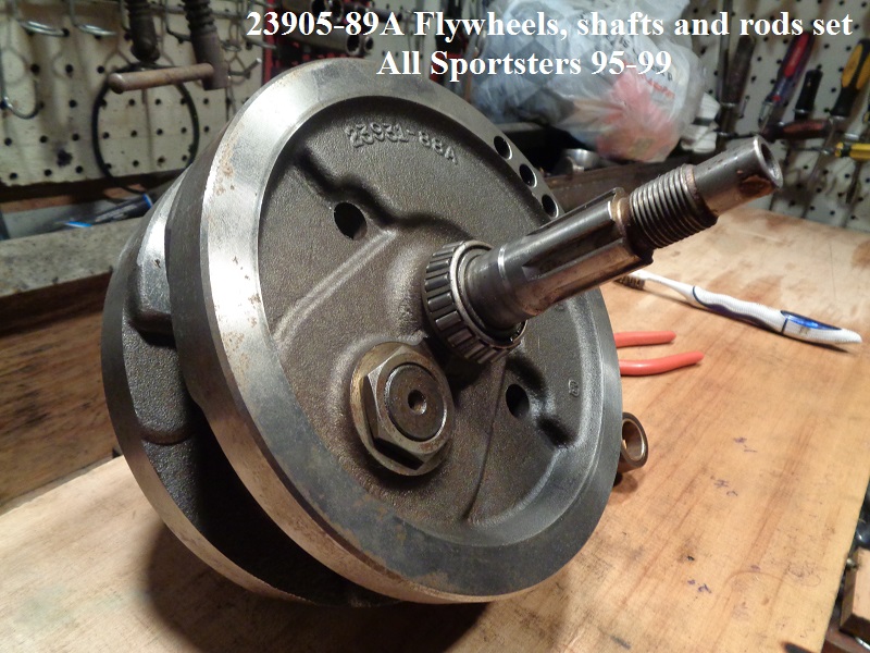
Sold as a unit: part number (23905-89A) consists of the flywheels, shafts and rods.
Each flywheel casting number (23931-88A)
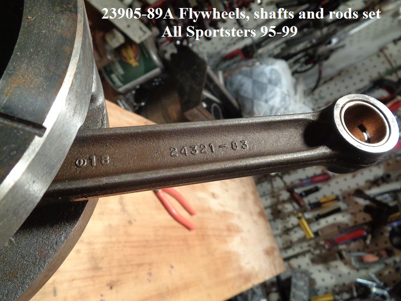
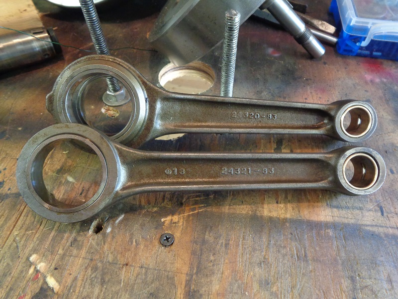
Connecting rod set: part number (24275-86A)
Left connecting rod casting number (24320-83)
Right connecting rod casting number (24321-83)
Rod bearing set (24354-87A)
Rod bearing race - front (2)-(24341-52A)
Rod bearing race - rear (2)-(24352-52A)
Piston pin bushing std (2)-(24331-36), .01” O.S. (24332-36
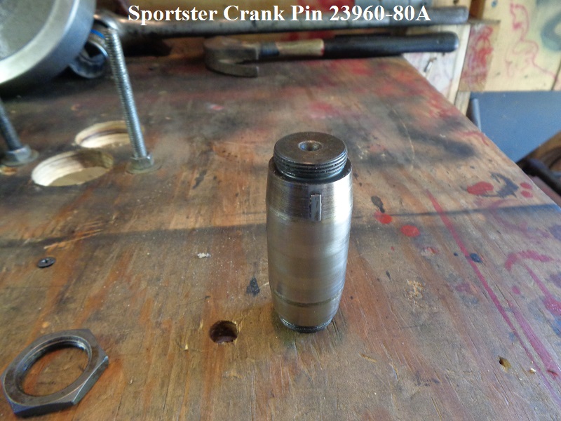
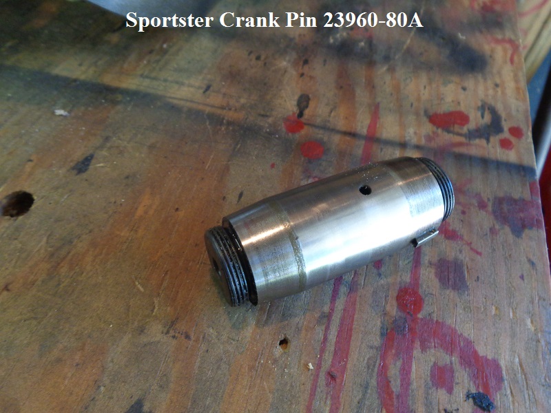
Crankpin std (23960-80A), .001“ O.S. (23948-87), .002” O.S. (23949-87)
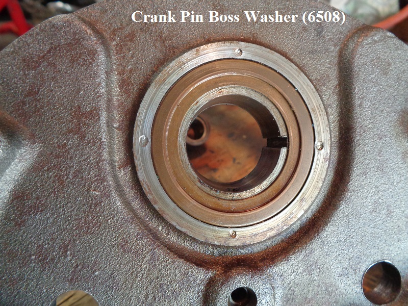
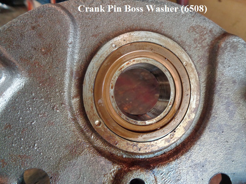
Crankpin boss washer (2)-(6508)
 |  |
 |  |  |
 |  |  |
 |  |  |
00-03
Flywheels
91-99 (all) Flywheels.
Flywheel set part number (23905-89A).
Each flywheel casting number (23931-88A).
| 91-99 Flywheels 13) | |
 |  |
| Crank pin boss washer (5608) 14) | |
 |  |
From '91 to '03 the Crankshaft/Flywheel was balanced according to the engine size, either for 883 pistons or 1200 pistons. From 2004-later, the flywheels are balanced to be between the weight of the 883 & 1200 pistons. 15) This is one reason why riders would use Wiseco pistons in early (pre-2004) 883 to 1200 conversions - the Wiseco 1200 piston & pin was closer to the weight of the 883 combination rather than the 1200 piston & pin from HD.
Crank Pin
Crank pin (23960-80a) used from L81-03.
| L87-03 crank pin 16) | ||
 |  |  |
Connecting Rods
 | 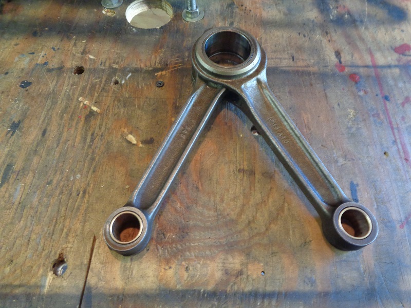 |  |
 |  |  |
Pinion Shaft
Removing / installing the pinion shaft nut
To remove or install the pinion gear nut,
You'll need to lock the pinion gear from moving while turning it.
It's very important to hold the crank on the pinion side with an appropriate pinion locking tool whenever you take the pinion nut off or put it on.
If you hold the crank still from the primary side (or by putting the bike in gear and holding the brake),
The twisting torque applied to the pinion nut gets transmitted through the crank, from one side to the other.
The crank pin is not designed to resist much twisting force.
You'll risk scissoring the crankshaft (knocking the crank out of true), which requires a full tear-down to fix. 17)
So this is one of those situations where it's best to use the proper tool. 18)
The pinion nut takes a 15/16“ wrench size.
90 and Prior Models (4 Speed)
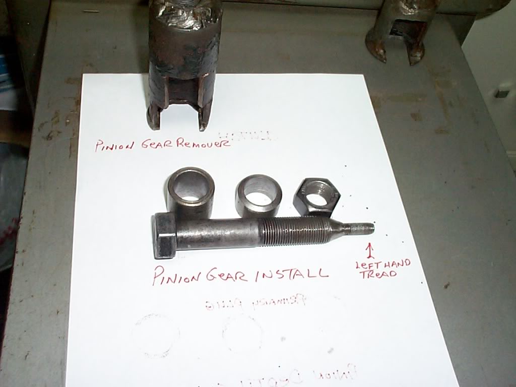 |  | 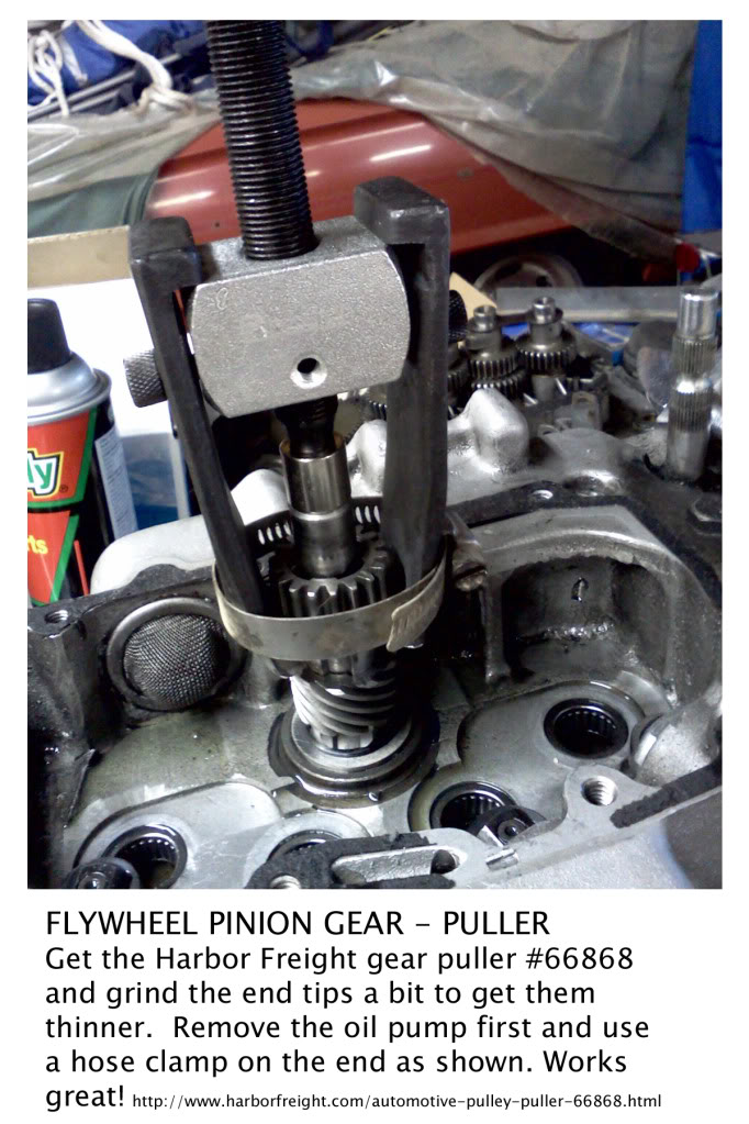 |
| Homemade Pinion Gear / Removal / Installation Tools 19) | Homemade pinion gear press 20) | Pinion Gear Puller 21) |
|---|
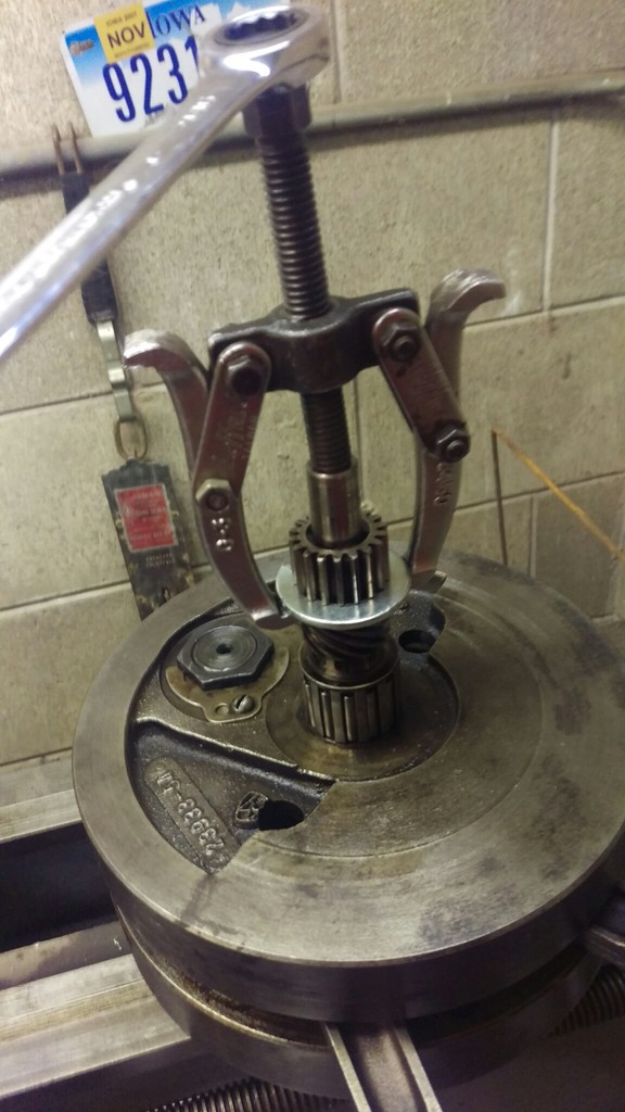 | 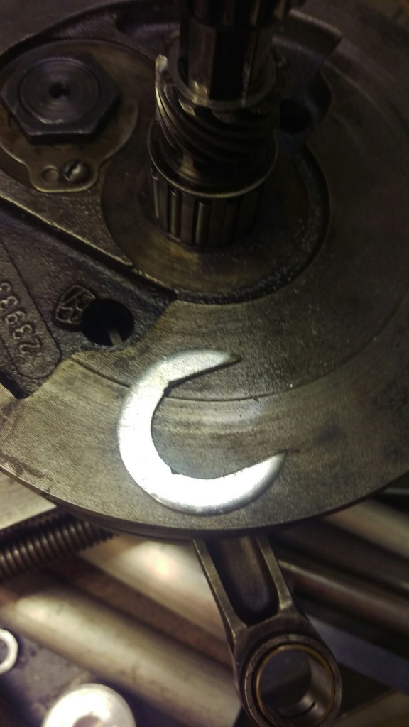 | 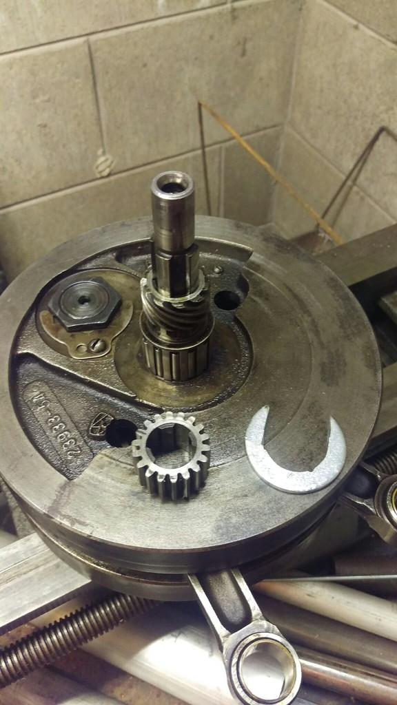 |
| Large fender washer cut into a “C” shape and a gear puller | ||
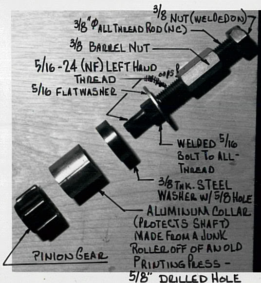
| Homemade Pinion Gear Puller 22) | ||
 |
| 3/8” stainless steel plate with 20° spokes (for 18 teeth), sawed initial groove to depth and widened it with files |
| Homemade pinion gear locking tool for '89 models 23) |
91 and Up Models (5 Speed)
See also in the Sportsterpedia:
Oil Pump Drive Gear
Origin of the Grindlock Tool
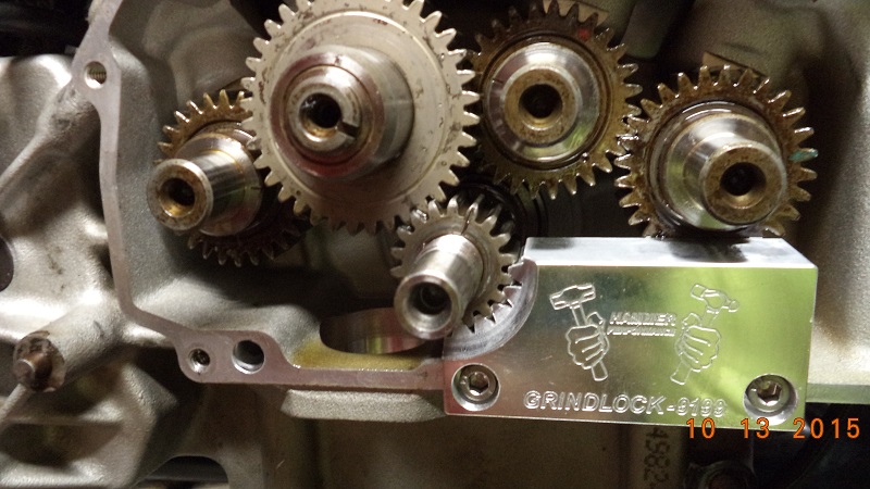
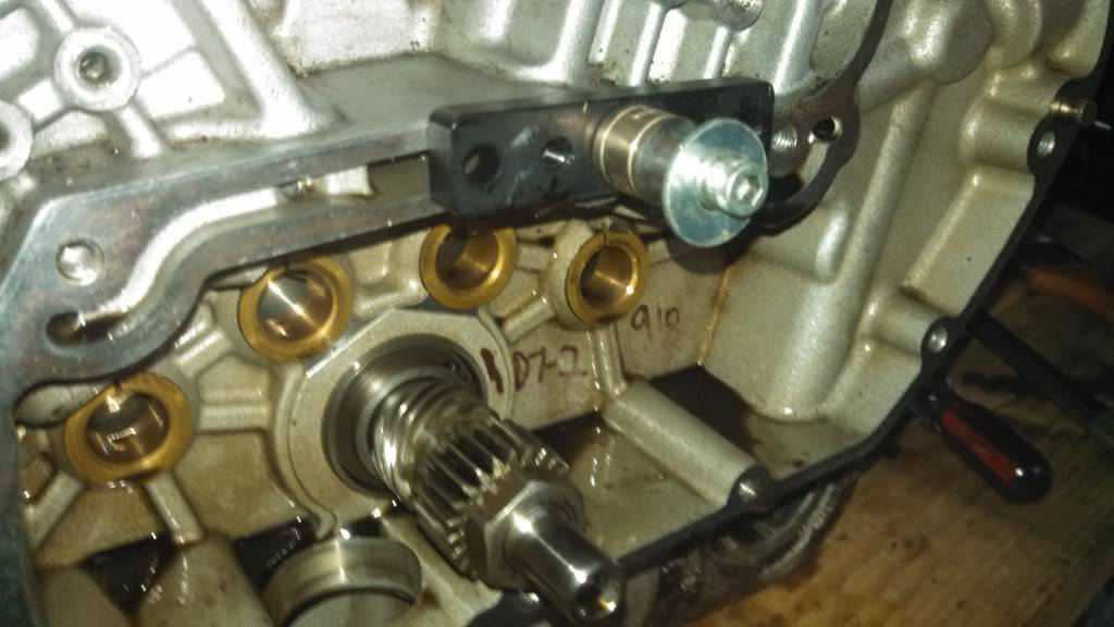
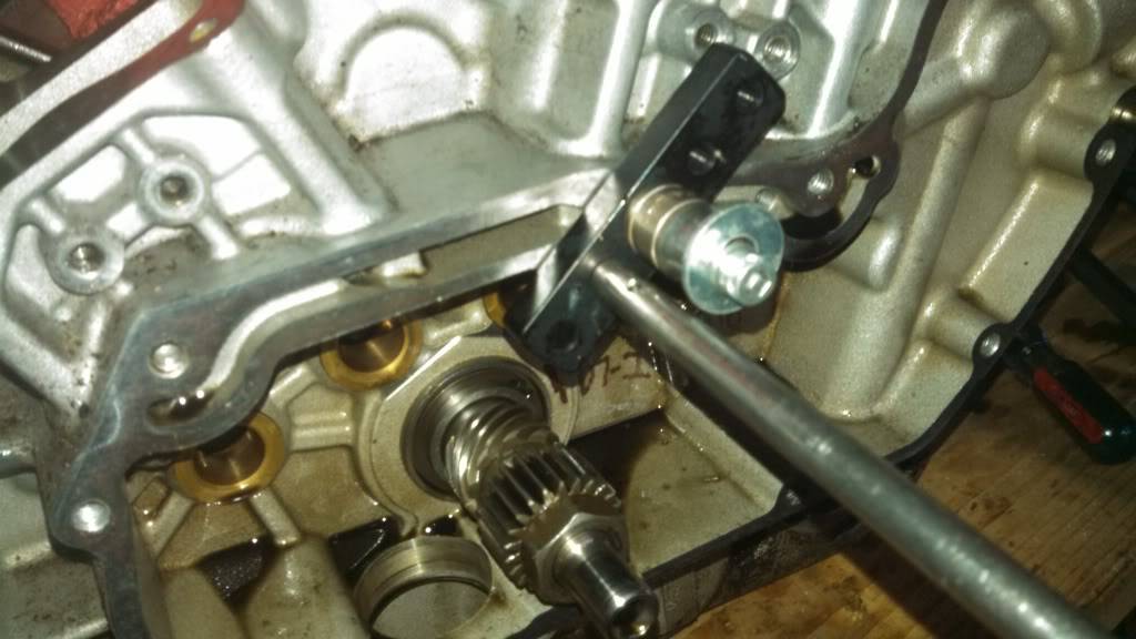
- You can use a 15/16“ wrench or deep well socket to remove / install the pinion gear nut.
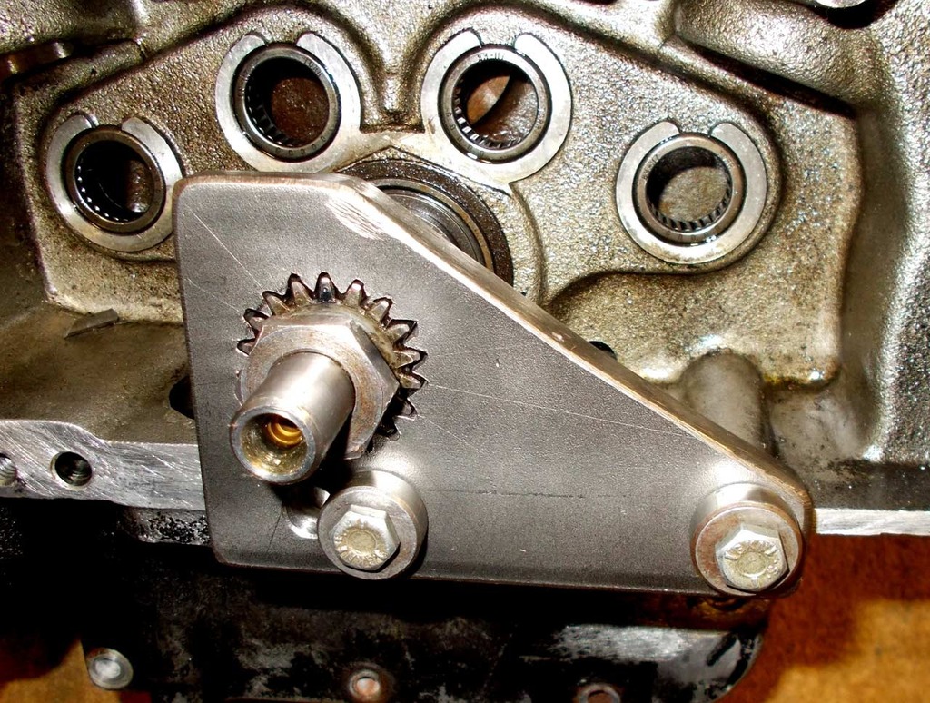
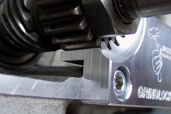
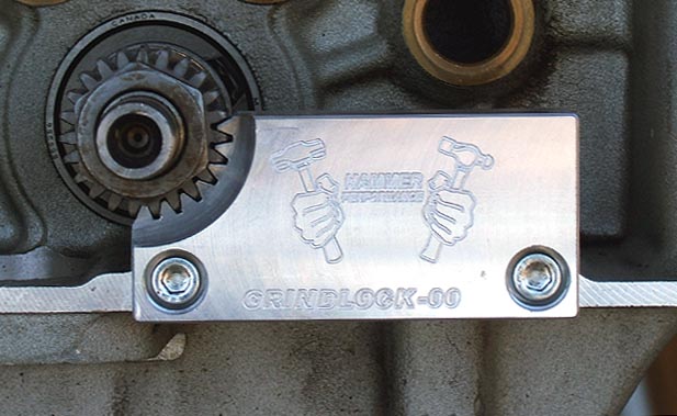
- The Grindlock Pinion Shaft Locking Tool engages for the full depth of the pinion gear for max. strength.

- Once the pinion shaft nut is removed, the pinion gear may or may not slide off by itself.
You can use a gear puller to remove it if it is stuck on.
- It's very important to hold the crank still from the cam side (not the primary side) when torquing the pinion nut. 31)
If you for example put the bike in gear and hold the rear brake and torque on the nut, you run the very real risk of knocking the crank out of true.
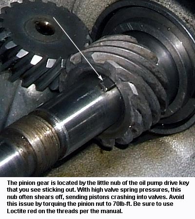
It's not designed to transmit torque from one side to the other and it tries to twist the crankpin connection. - In respect to the key shearing, it's a very common issue particularly when heavy valve springs are used.
However, it shouldn't be the one thing that keeps the gear from spinning. The clamp load should do that.
The caption in the second pic below describes the fix:
Loctite red and 70ft-lbs instead of the factory specified 50ft-lbs. You won't have this issue again.

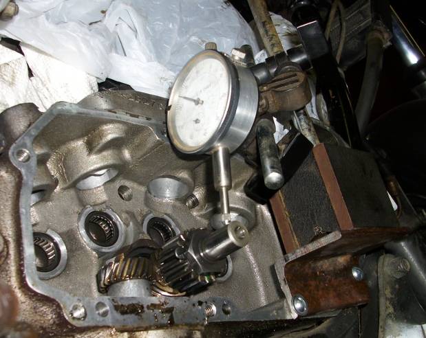
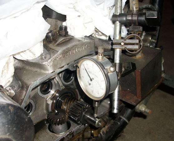
Pinion Gear Runout
| Attach a scrap piece of metal to the outside of the gearcase and position a gauge holder on it so it won't move while turning over the engine. 34) | ||
 |  |  |
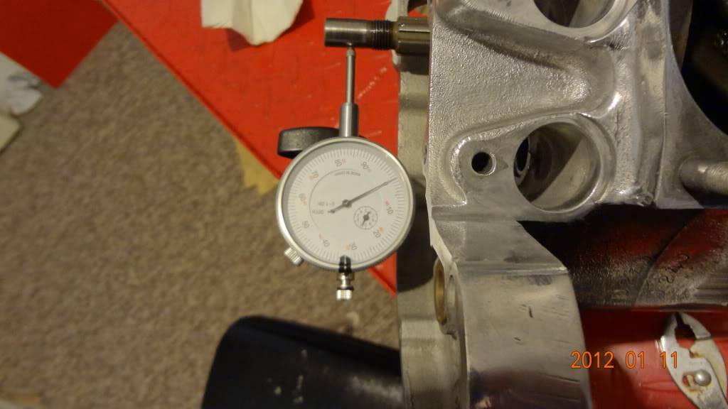
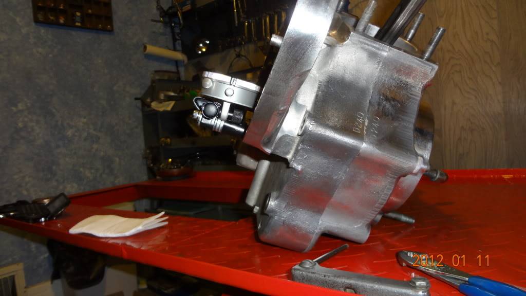
| Install a dial gauge on the holder with the pointer on the pinion shaft. Find the lowest spot while turning the engine over and 'zero' the indicator. 35) | This setup is made with a piece of angle iron for the magnetic base to stand on 36) | |
 |  |  |
| This gauge post is threaded into a cover mount hole. 37) | |
 |  |