Table of Contents

IH: Engine Mechanicals - Sub-01G
Ironhead Gearcase/Cam Cover Removal and Installation
Cam/Gearcase Cover Removal
Article by Dr Dick of the XLFORUM 1)
- Take the cam cover off without dropping anything in the drain pan or on the floor while preserving where all the shims are positioned.
- Try not take the cams out unless you Need to.
- Strip all needed parts to get to the cam cover only.
- Carb
- Mag
- Exhaust
- Pegs
- Kicker
- Shifter
- Breather tube
- Generator
- Kicker cover
- Pushrods
- Remove all screws from cam cover.
- Now look in the gap, and with a skinny screw driver, push all the cams back into the engine so that they won't come out with the cover.
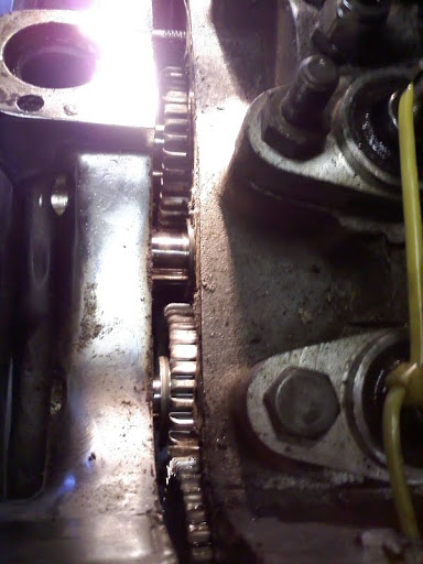
- Now, you will be able to see the shims if there are any in there.
- Use an ice pick to work any shims, that are hanging on the cover bushing flanges, back onto the cams.
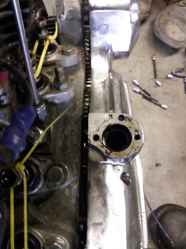
- Make sure the cams hang inside the motor using the skinny screwdriver again as you work the cover off.
Note that the cover is still engaged to the cams and that they are slid fully into the motor side.
| Keep this up until you have the cover off 4) |
 |
Inspection
- Inspect the cam bushings. Check the clearances per the service manual and replace any out of service bushings. Also check for scoring or scratches. Click Here for Cam Bushing Measuring / Removal / Installation Tools. Click Here to view the page in Sportsterpedia on Installing, Pinning and Reaming Cam Bushings.
- Inspect the point cover/ignition seal in the cover (see below).
- Look for ID leaks; a marred cam journal, seal lip not getting up on the full journal diameter or a missing dog bone thrust plate on far side of cam. 5) Also look for a blocked drain hole (putting the seal in too far can do this). The seal goes flush to outer surface. A new bushing too long hitting the seal lip when the seal was installed would do it also. Same as the seal bore not concentric to the cam bushing (holds seal off center).
- Look for OD leaks; the seal bore nicked, tearing the seal OD when installing it.
- Look for scratches, gouges or wear marks on the cam shaft where the seal seats. If there are any, they need to be removed or the shaft changed. Also check if there are any gouges or cracks around the outside diameter of where the seal fits in (bore). These can be put there during seal removal and let oil seep out around the outside of the seal. They can usually be scraped or filed back flat. You can make a scraper by grinding the teeth off the end of a three-sided file.
- Inspect the breather vent/bushing in the cover for damage/debris/obstruction. Click Here to go to the IH Crankcase Ventilation page in Sportsterpedia for pics and info for different year covers and breathing systems. The breathing passages can get stopped up, especially if you have sand blasted the cover, but it can also stop up from old oil on extended shutdowns.
Preparation
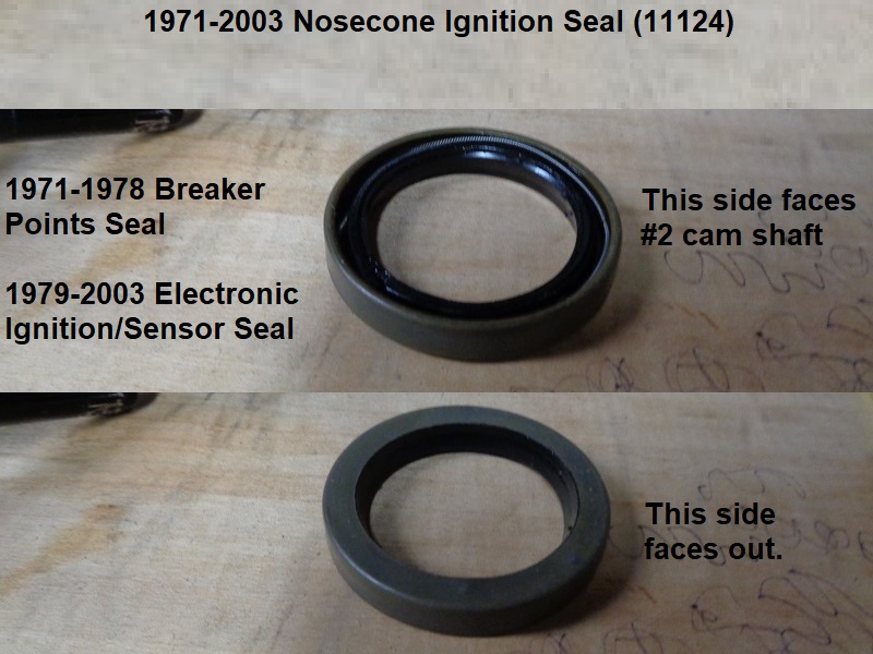
Breaker Points/Nosecone Ignition Seal
This is a steel shell radial shaft seal (HD# 11124) installed in the cam cover.
It surrounds and seals #2 cam when the cover is installed. Also used on 1986-2003 model Sportster cam covers.
Dims per XLForum member, Fizzle:
OD 1.570“ (39.878mm), ID 1.050” (26.67mm), W 0.248“ (6.2992mm)
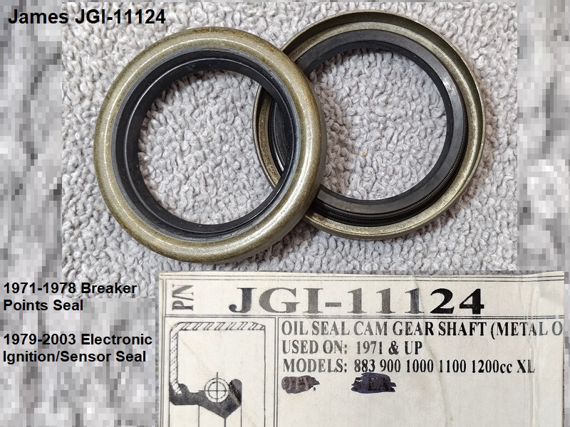
Other brands include James (JGI-11124), Cometic (C9355), Athena (51-A210), Custom Chrome (54-043).
The rubber shell HD Genuine double lip version is part number (11124-DL).
Other brands include James (JGI-11124-DL).
NOTE: SKF makes a radial shaft seal with a part number of 11124 but that IS NOT AN HD PART NUMBER.
SKF 11124 IS TOO BIG TO FIT THE COVER and they don't show a compatible seal in their catalog for this application.
HD Seal 11124 (L), James Gasket Seal JGI-11124 (R):
Seal removal/installation
Removal
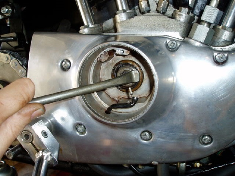
- With the cover installed: (do-able but arguably not the best way)
| Pulling oil seal gently with small bicycle tire iron. 10) |
 |
Installation
The seal is pressed into the cam cover to seal #2 cam shaft as it protrudes thru the cover behind the the points or ignition plate.
- Lightly grease the lip (the part that surrounds the cam). However, the seal OD should be installed rather dry or with an appropriate sealer (not RTV).
A thin layer of non hardening aviation gasket sealer etc. around the seal OD lubricates the installation. 11)
(and helps stop leaks around imperfections in roundness)
- Then you can tap a new one in with either an oil seal installation tool or a socket of appropriate diameter.
- If you decide to pull the cover to change the seal (better idea), remove the push rods FIRST. 12)
Cam Cover Gasket
Make sure to use the correct gasket for your engine/cover specifics.
Click Here to view a list of cam cover gaskets and more information on case changes that affected the gaskets.
There were changes to the upper feed galley that dictate a specific gasket, especially between 1979-1982 models.
The upper oil feed galley was redesigned during the 1979-1982 and according to the MoCo, the gasket must fit the case design.
Click Here for pics of the changes to the upper oil feed galley in the right case.
Installing the Cover
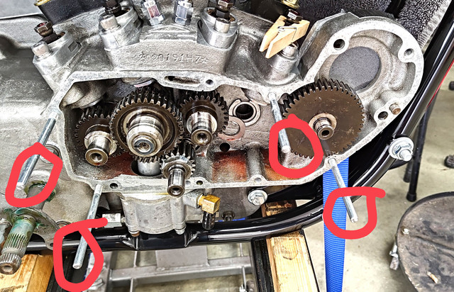
Easiest way to install the cover is to cut a few pieces of threaded rod about 3-1/2” long (or cut heads off long 1/4“ screws/bolts) for cover “holders”.
Insert a rod by hand into two or three mounting holes turning to get several threads in (it doesn't have to get tight).
Install the cover gasket and cover over the rods and push lightly on the cover to take up any space to the gearcase.
The rods help the cover come up evenly without binding anything.
Install several mounting screws in unused holes to “just snug” then remove all the rods and install all the other mounting screws “just snug”.
Then use the torque specs and torque sequence below.
Cam Cover Fastener List
Click Here to read “Finding Acceptable Lengths for Gearcase/Cam Cover Screws” in the REF section of the Sportsterpedia.
The fasteners for 1952-E1981 can be changed out to socket head screws to keep from having to deal with slotted, phillips or posidrive heads.
The list below shows factory screws and sizes.
Here is a link to Bolt Depot for their “Socket Flat Head” fasteners page (zinc, chrome, stainless or allow).
- 1952-1970 K/Sportster Cam Covers Use:
- (9) Cover Screws.
- 1/4” x 20 x 1-1/2“ Oval Slotted Head Bolt Screw (2345) x 3.
1/4” x 20 x 2-5/16“ Oval Slotted Head Screw (2353) x 5.
1/4” x 20 x 2-1/4“ Oval Slotted Head Screw (2352) x 1. - Colony replacement kit (8895-9)
- (2) Generator Mounting Bolts.
- 5/16” x 24 Bolt (30013-52) x 2. Angled shank under head to sit flush in mounting hole.
- (2) Solid Dowel Pins.
- .308“ dia x .690” long (375). Gearcase has matching dowel pin holes in front and rear.
- 1971-1976 Sportster Cam Covers Use;
- (8) Cover Screws.
- 1/4“ x 20 x 1-3/4” (1971-1973 Phillips Head Screw, 1316W x 3) or (1974-1976: Posidriv Head Screw, 1316W x 3).
1/4“ x 20 x 1-1/4” (1971-1973 Phillips Head Screw, 1317W x 1) or (1974-1976 Posidriv Head Screw, 1317W x 1)
1/4“ x 20 x 2-1/4” (1971-1973 Phillips Head Screw, 1370W x 4) or (1974-1976 Posidriv Head Screw 1370W x 4)
- (2)- Generator Mounting Bolts
- 5/16“ x 24 x 3-1/4” Hex Head Bolt (30013-71) x 2.
- (2) Solid Dowel Pins.
- .308“ dia x .690” long (375) x 2. Gearcase has matching dowel pin holes in front and rear.
- 1977-E1981 covers use;
Note: screws for 1979 XLS were painted black, part#s were different for that fact.- (8) Cover Screws.
- 1/4“ x 20 x 1-3/4” Posidriv Head Screw, (1316W) x 3.
1/4“ x 20 x 1-1/4” Posidriv Head Screw, (1317W) x 1.
1/4“ x 20 x 2-1/2” Posidriv Head Screw (1381) x 4.
- (2)- Generator Mounting Bolts
- 5/16“ x 24 x 3-1/4” Hex Head Bolt (30013-71) x 2.
- (1) Solid Dowel Pin.
- .308“ dia x .690” long (375). Cover has hole for rear pin but gearcase doesn't. Pin is used in front of cam cover.
- L1981-E1984 covers use;
- (9)- 1/4“ Cover Screws.
- (2)- Generator Mounting Bolts.
- 5/16” x 24 x 3-1/4“ Hex Head Bolt (30013-71) x 2.
- (1)- Solid Dowel Pin (375), .308” dia x .690“ long. Pin is used in front of cam cover.
- L1984-E1985 covers use;
- (9)- 1/4” Cover Screws.
- (2)- Oil Filter Mount Bolts
- 5/16“ x 18 x 3-1/4” Hex Head Bolt (4392) x 2
- (2)- Solid Dowel Pins (375), .308“ dia x .690” long.
1 dowel pin is used in front on gearcase. 1 dowel pin is used in the right case, lower tranny area.
Torque Specs
Due to the early manuals NOT having torque specs for these screws, many developed a “torque stop” in their wrists and elbows.
However, in order to develop the “feel” for when to stop, you have to bend or break some screws first.
Do not try and stop a leak by tightening the screws any harder than you would installing them in the first place.
Click Here to read about, Using “Feel” While Tightening, on the torque wrench usage page in the Sportsterpedia.
Caution: Too much torque on fastener's can create a leak or make a leak worse than it is.
For those who would like a guide to proper torque on the screws, specs are below.
It's always a good idea to clean the screw threads and the threads in the aluminum case before using them.
Any dirt/oil debris in the threads WILL change the torque that you actually apply to the screws.
You should be able to run a screw in each hole in the gearcase before installing the cover and bottom it out by hand without any binding or hesitation.
If not, the threads need attention before proceeding.
If you can't blast the threads clean, Click Here to see the article in the Sportsterpedia on chasing threads with a tap or thread mender tool.
- Cam Cover Screws:
- 1957-1969 FSM: There are no torque specs or sequence for cam cover screws other than “tighten all screws evenly”.
- Snug plus a nudge is a general rule.
- Use 1970-1985 specs for best results (80-110 in/lbs).
- 1970-1985 FSMs:
- Tighten all cam cover screws to 80-110 in/lbs evenly.
- Generator Bolts (1957-E1984): 1957-E1984 FSMs have no reference to generator bolt torque.
- Snug plus a nudge is the general rule.
- 70-85 FSM makes no distinction between cover mounting screws and generator mounting bolts.
- Oil Filter Housing (L1984-1985):
- Tighten bolts to 13-16 ft/lbs
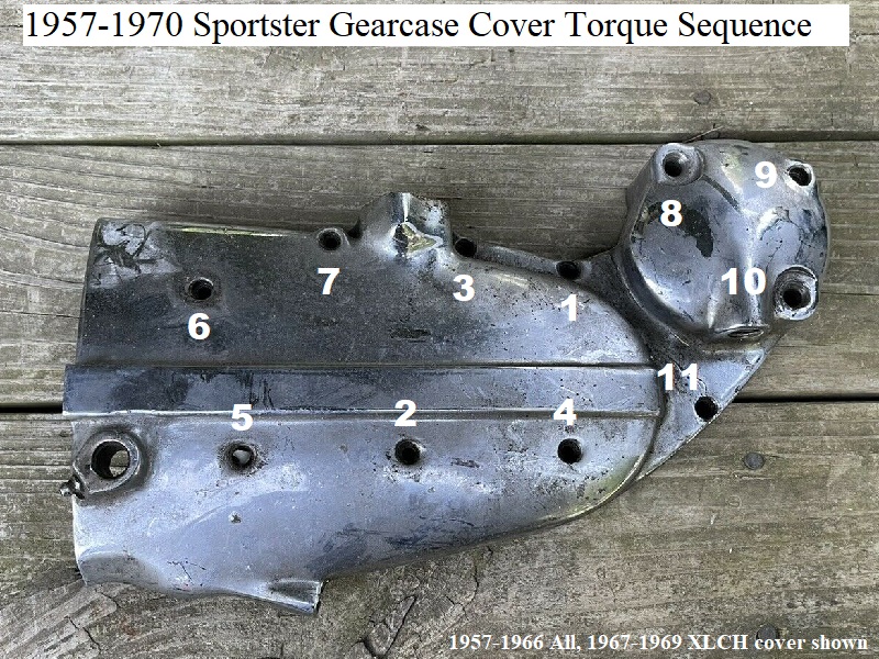
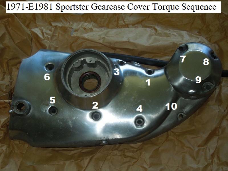
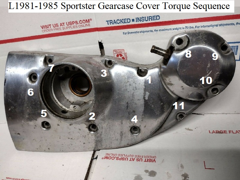
Torque Sequence
The only sequence for tightening the cam cover screws in Ironhead manuals is “tighten all screws evenly working opposite from one another”.
That's basically referring to what is commonly known as a “cross pattern”. Trouble is, the screws are not all in the position to accept a cross pattern.
Some are on the sides and corners and you can mess this up tightening the wrong ones first or last.
Tightening one screw effectively loosens other screws so the process is still a little wanting from the manuals.
It wasn't until 1992 that the MoCo included an illustration in the FSM showing the sequence to use for torque on these bolts.
It is a cross pattern in the middle and following side to top screws in pattern and this same sequence can be used on 1957-1991 model cam covers.
Since getting all the screws evenly tightened has always been the goal, the 92 torque sequence can't hurt if you'd like to use it.
This will help keep you from snapping screws, cracking the case or creating oil leaks.
Don't try to get to the torque spec all at once. Divide the intended torque into steps using at least 2 full passes (3 is better).
It's a small torque spec but even torque on all screws is the goal, not the spec.
Click Here to see the torque wrench page.
On the right menu, click on “Using a Torque Wrench” scroll down to Technique.
It's safer to use a beam type wrench on these fasteners than a clicker type wrench.
| Beam type in/lb torque wrench w/ hex adapter 14) |
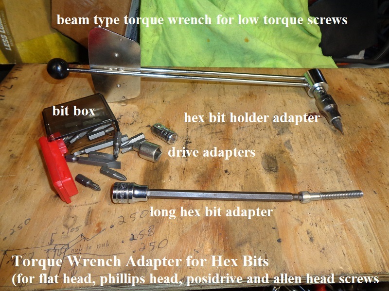 |
Below are pics with the adapted sequence shown. Use at your own discrepancy.
Using this sequence, you will get more of an equal torque around the cover, better fit and less chance of leaks later.