Table of Contents
This is an old revision of the document!

IH: Engine Mechanical
Engine Mounts
This page has been created from XLForum posts and pics, era model Sportster parts catalogs, parts catalog supplements and pics / documentation from JW Boon.com or NOS Parts.nl. 1)
Removing / Installing Motor Mounts
From the Service Manuals
The ironhead factory service manuals lay out the procedure for 'stripping the motorcycle for repair'.
This covers the procedure for removing / installing the motor and also includes the motor mounts.
However, the whole story is not in the manual.
You can induce added vibration and potential for cracks in the mounts or cases if the mounts aren't installed properly.
Below is the procedure from the manuals for removing and installing the mounts. 2) 3) 4)
To remove the motor (given all other particulars have been removed as this is strictly regarding the mounts themselves);
- 57-78:
Remove top engine support bolt located between the cylinders.
Be sure to note how many shim washers are between the head bracket and the frame lug so they can be re-installed with the engine.
79-85:
Remove the rear top engine support bracket and then the front top engine support bracket.
On 83-up engines, remove the VOES and then the rear top mount. - Remove the right crash bar bolt (if equipped).
- Loosen but do not remove the top front bolt from the lower left plate.
- Remove the three remaining bolts and left crash bar bolt (if equipped).
- Remove the two top bracket support bolts (1 from each head) along with the bracket assembly.
- Remove the two top rear engine mounting bolts and regulator ground strap.
- Remove the stoplight switch (66 and earlier), rear brake lever and spring (74 and earlier) and gear shift foot lever (75-up).
- Remove left footrest 78<.
- Remove the two bottom rear engine mounting bolts.
- Remove the top left bolt from the lower mounting plate.
(The 79-85 FSM simply states to remove the hardware that attaches the front and rear of the engine to the frame).
To install the motor (Again, this is strictly regarding the mounts themselves and all other parts will need to be addressed that were removed);
The 79-85 FSM doesn't give instructions on putting everything back together.
- Install the right crash bar bolt (if equipped).
- Install the two bottom rear engine mounting bolts
- Install the two top rear engine mounting bolts and regulator ground strap.
- Install the top left bolt from the lower mounting plate.
- Install the three remaining bolts and left crash bar bolt (if equipped).
- (It's assumed to tighten) the top front bolt from the lower left plate.
- Install the stoplight switch (66 and earlier), rear brake lever and spring (74 and earlier) and gear shift foot lever (75-up).
- Install the two top rear engine mounting bolts and regulator ground strap.
- 57-78:
Install the 2 top bracket support bolts (one on each head) along with the bracket assembly and the top engine support bolt located between the cylinders.
(Be sure reinstall the correct amount of shim washers as removed).
Further explanation on installing motor mounts from XLForum members
When following the manual procedures, it's possible and actually common to tighten everything up only to find the motor position has cracked the rear mount.
Your motor needs to be “cradled” in the frame. 5)
If it's just put in and tightened up it could be out of alignment and stress one area more than others.
That can set up a harmonic that gets worse at a specific rpm range.
The way the rear mount is designed, it determines the motor location. 6) 7)
The rear mount has to be tightened first, then the other mounts.
It's possible to probable that most rear mount breakage can be attributed to improper assembly techniques, broken frames or loose / missing mounts.
You cannot “pull” the rear mount into place against the other mounts as it will break the mount due to the high amount of leverage from the other mounts.
The front frame tubes may spring sideways slightly but that is the only allowable “pulling”.
All mounts should fit nicely and naturally before tightening.
- The rear mount is fixed (as in not adjustable).
It has to be tightened first to the motor (snug the top 2 bolts, tighten the 3 lower nuts / bolts then tighten the top 2).
Then tighten the 4 frame to mount bolts before even installing the other mounts.
See Rear Mounts below for more details. - After the rear mount is tightened, then install the front mounts.
Take care to keep the motor in it's natural position after rear mount is tightened. Do not pull or wedge the motor against the rear mount.
If things don't fit right, perhaps the frame is bent or the rear mount position on the motor needs to be adjusted (which is difficult if not impossible).
Keep in mind that all bolts must go through all of the parts without any binding AFTER the rear mount is tight.
Work on any front bolt holes with a rat tail file to slot any holes in the plates that do not line up perfectly.
(The bolts must pass through with no interference).
Pay special attention to the use and correct positioning of front mount spacers and grippy washers (OEM recommended).
NOTE:
There are many aftermarket front mount bolts that are longer to facilitate installing forward footpeg mounting brackets that get sandwiched with the mount plates.
Do not install a long bolt in the front mount upper rear position (you'll break the cases!).
See Lower Front Mounts below for more details. - After the front mount bolts are tightened, install the top mounting bracket(s).
Shim any gaps in the upper mount(s) or slot bolt holes as needed with large diameter washers.
Read more on shims below.
See Top Mounts below for more details per year model.
All else fails;
There is sometimes some wiggle room on the rear mount. 8)
Loosen all the bolts slightly and give it a yank in the direction you need hold and tighten.
DO NOT pull things into position or jam bolts in under pressure!
The bolt holes must line up naturally or the rear mount will break in use.
Don't get in a rush, it will be costly later (regrets if nothing else).
You don't have time to NOT do it right. It will NOT get done later and will leave you beside the road when it breaks.
Put it together right the first time, or you will be forever breaking down.
Another way to do that is to hang the motor by the center (head mount) on the frame. 9)
Use no washers,leave the front mount bolts out and the front mounts loose at the engine.
Start all of your rear mount bolts but don't tighten them up yet. Start all of your front mount bolts but leave them loose.
Now tighten up the rear mount bolts evenly until the rear mount is seated and torque the bolts.
Snug up the front mounts but not tight. Remove the top mount and add washers until you have about 1/32“ play at the top mount.
Tighten front mount bolts, frame and engine. Tighten top mount and you are done.
Regarding Shims
Shimming Top Mounts
- The top mounts should be shimmed if they do not fit nice against the frame.
- Before tightening top mounts, check to make sure there is no space left between the mount and rocker box (or heads respectively).
Don't allow any of the mounts to be “stressed” or “pulled” into position by tightening the bolts.
The mount is flat at each bolt hole and any space between it and the recessed hole on the rocker box can stress therefore break the mount.
If it doesn't break the mount, the stress can allow the rocker box to be “stress” pulled upward and create a leak at the gasket. 10)
Use extra washers to add / change as needed to achieve “zero space left” before tightening. Remove the mount if need be to add shims.
Then go back through the installation steps to just snug the entire assembly before torque is applied. - Normally washers are used as shims although some have bought or made spacers from hollow sleeves.
Either way, the shims need to be flat on top and bottom to allow for even torque across them.
Store bought spacers have a habit of warpage or imperfections on the ends which may need to be straightened before using.
If the top or bottom of a shim is not true flat, any high/low spots can turn during vibration and end up loosening the motor mount assembly. - Use hardened flat washers (soft washers will crush or taco and not hold correctly) over slotted holes and grade 8 nylock nuts.
Use hardened washers against aluminum also. Pyramid stack hardened washers for the big single upper mount bolt.
Use a fender washer or make a large diameter shim if needed to close any gap (fine thread grade 8 bolt & nut).
See Top Mounts below for more details per year model. - The parts books “hint” thru illustration that washers can be used between the frame and upper front motor mount if needed to take up space as needed.
However, placing the bracket against the frame gives maximum clamp space to the assembly without added “tilt-ability” of the bracket.
Placing spacers below the bracket and leaving the bracket against the frame will give more rigidity to the assembly.- 1/16” washers (6702) suggested for 78-81 models and 5/64“ washers (6702) suggested for 82-85 models.


Bolt Type and Lengths
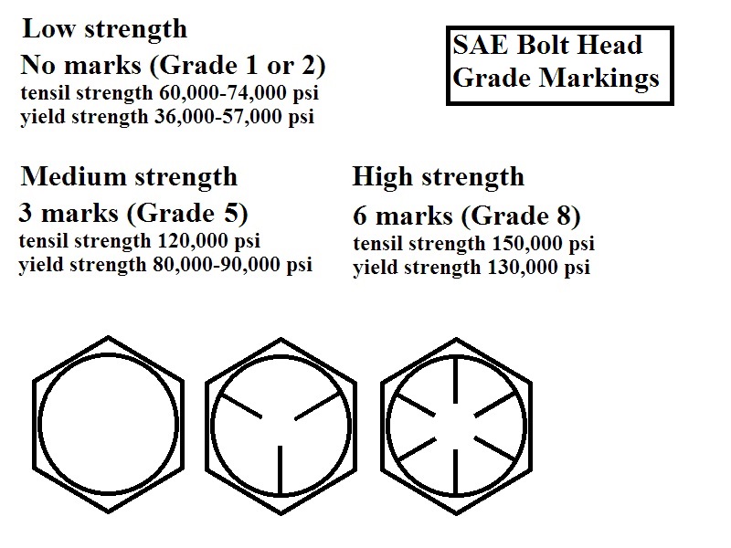
There are conflicting views on what grade bolts to use.
Some say it's best to use the original bolts which are grade 5 SAE fine thread (3/8”x24) and that grade 8 bolts are seen as overkill.
The theory is that a grade 8 bolt is more brittle and doesn't have as much elasticity as a grade 5 bolt.
And that upon a collision, a grade 8 bolt would break or shear whereas a grade 5 bolt would bend or deform (but still remain “intact”).
(That reasoning is debatable however. Both have been used successfully)
Others say a grade 8 bolt is always harder, and stronger in tensile and shear than a grade 5. 14)
(30,000 psi higher in tensile strength and 40,000-50,000 psi higher in shear strength).
If loaded to failure, grade 5 will have more % elongation than a grade 8 before it finally breaks, but will still break at a lower stress than a grade 8.
If fasteners are elongating that much in any application, there are other problems.
Lower grades are used to save cost over higher grades when cost is a factor. Lower grades offer no mechanical advantage.
The MoCo's first use of grade 8 motor mount bolts was in 1986.
Rear mount to case bolts \ studs
Rear studs
These are the three horizontal studs in the rear that the mount slides over and into the center valley between the cases.
The nuts secure the mount to the rear of the case.
- Stud (3ea)-(24817-52) 3/8“x3-1/4” grade 5 zinc, case end is threaded 3/8“x16, nut end is threaded 3/8”x24.
- Nut (3ea)-(7775, Flexlock) 3/8“x24 or (7775NY, Nylock) 3/8”x24x9/16“.
Top bolts / studs
These go in on the 'shelf' or top of the engine cases in the rear.
- 1957-1975 bolts: All
- 3/8”x16x1-3/16“ parkerized, hex head.
Part # (4348)
57-66 XLH/XLCH & 67-69 XLCH (4 ea.)
67-75 XL/XLH/XLS (2 ea.)
- L1970-E1975 studs:
- L70-E72 XLCH
1 bolt in the left side and a stud (24825-66) 3/8”x1-5/8“ parkerized in the right side.
The case side is 3/8”x16, the other side is 3/8“x24. - L72-E75 XLCH
1 bolt in the left side and a stud (24824-67) 3/8”x2“ grade 5 zinc in the right side.
The case side is 3/8”x16, the other side is 3/8“x24.
- 1976 XLCH bolts :
- 3/8”x16x1“ grade 5 zinc, hex head.
Part # (2879W) (2 ea.)
- 1976-1978 XL/XLH/XLS bolts :
- 3/8”x16x1“ grade 5 zinc, hex head
Part # (2879W) (2 ea.)
- 1977-1978 XLCH bolts:
- 3/8”x16x1-1/4“ grade 5 zinc, hex head
Part # (4716W) (2 ea).
- 1979-1985 All, bolts:
- 3/8”x16x1-1/4“ grade 5 zinc, hex head.
Part # (4716W) (2 ea).
Rear mount to frame bolts
Top bolts
- 1957-1962:
- 3/8”x24x1-1/8“ parkerized, hex head.
Part # (4336) (2 ea). - Replacement in 63 was 3/8”x24x1-1/8“ grade 5 zinc, hex head.
Part # (4336w) (2 ea).
- 1963-1972:
- 3/8”x24x1-1/8“ grade 5 zinc, hex head.
Part # (4336w) (2 ea).
- 1973-1978:
- 3/8”x24x2-1/4“ grade 5 zinc, hex head.
Part # (3945) (1ea). - 3/8”x24x1-1/8“ grade 5 zinc, hex head.
Part # (4336w) (1ea).
- 1979-1981:
- 3/8”x24x1-1/8“ grade 5 zinc, hex head.
Part # (4336w) (1ea). - 3/8x24x3” grade 5 zinc, hex head.
Part # (4415) (1 ea).
- 1982-E1983:
- 3/8“x24x3-3/4” grade 5 zinc, hex head.
Part # (3455) (2 ea).
- L1983-1985:
- 3/8“x24x3-3/4” grade 5 zinc, hex head.
Part # (3455) (1 ea). - 3/8x24x3-1/4“ grade 5 zinc, hex head.
Part # (4434W) (1 ea).
Bottom Bolts
- 1957-1960:
- 3/8”x24x2“ grade 5 zinc, hex head.
Part # (4380W) (2 ea).
- 1961-E1962:
- 3/8”x24x2-1/16“ cad, hex head.
Part # (4388B) (2 ea).
(although JW Boon lists this as 2-1/8” long) - Replacement in 76 was 3/8“x24x2” grade 5 zinc, hex head.
Part # (4380W) (2 ea) sold in 76 for 54-E62 models.
- L1962-1972:
- 3/8“x24x2-1/2” parkerized, hex head.
Part # (4452B - or HB) (2 ea). - Replacement in 76 was 3/8“x24x2-1/2” grade 5 zinc, hex head.
Part # (4412) (2 ea) sold in 76 for L62-up models.
- 1973-1978:
- 3/8“x24x2-1/2” grade 5 zinc, hex head.
Part # (4412) (2 ea).
- 1979-E1983:
- 3/8“x24x2-1/4” grade 5 zinc, hex head.
Part # (3945) (2ea).
- L1983-1990:
- 3/8“x24x3-1/2” grade 5 zinc, hex head.
Part # (4435W) (2 ea).
Lower front mount bolts
Use the spacers and single bolts of the correct length.
This keeps the frame tubes together around the sandwiched engine cases. Very important! 15)
Bolt lengths from parts catalogs (all have 3/8“x24 threads):
As you can see below, the lengths are far from being standard length and those lengths changed depending on what parts catalog you reference.
These are general guidelines for bolt sizes:
The front motor mount uses 3 different size bolt (lengths) for the 4 holes. 16)
The upper front and lower front holes (attaching to the frame) use the longest bolts.
The upper rear (through the case) uses the shortest.
The lower rear (through the case) uses the remaining middle length one.
If you use any other length bolts (in the case of the bolt going into the threaded engine plate at the top rear) use the 5-3/16” long bolt.
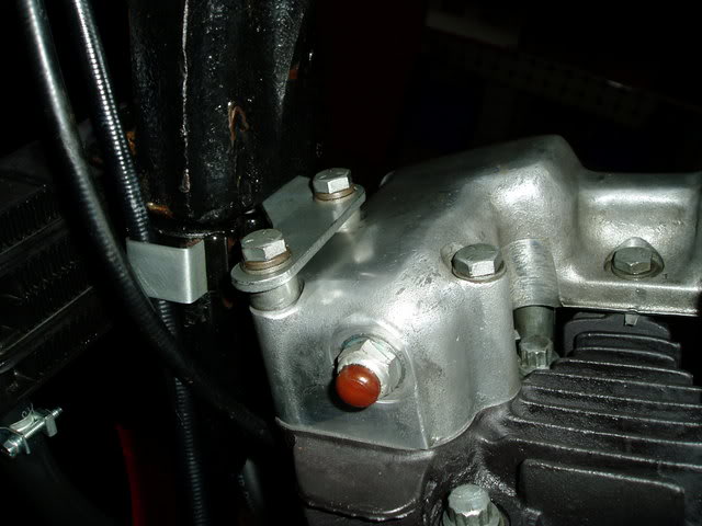
A longer bolt there will run into the generator mount and the lower one gets close to the oil pressure switch. 17)
-
- Top rear bolt (1), 5-3/16“ long (16235-52) grade 5 zinc.
Part number changed to (16235-52A) in the -78B catalog (issued in 1989) but the length stayed the same in the book.
Correct length is 3/8”x24x5-1/4“. - Bottom rear bolt (1), 5-7/16” long (16236-52) grade 5 zinc.
Changed to 5-1/2“ long (4413) in 1973 and sold for 54-76 models from the -78B catalog (issued in 1989). - Front bolts (2), 6-13/16” long (16237-57) grade 5 zinc.
'57 to '76 in the -78B catalog.
-
- Top rear bolt (1), 5-3/16“ long (16235-52) grade 5 zinc.
Changed to 5-1/4” long in -78A catalog (issued in 1981) for 77-78 models with the same part number for both lengths (16235-52).
The correct part number is (16235-52A) - Bottom rear bolt (1), 5-1/2“ long (4413) grade 5 zinc.
- Front bolts (2), 6-13/16” long (16237-57) grade 5 zinc.
-
- Top rear bolt (1), 6-13/16“ long (16237-57) grade 5 zinc.
Both the -79 and -79A parts books show a quantity of (3) for this size bolt (same size as the front two) instead of the 5-3/16” bolt.
Changed in 1980 to 5-1/4“ long which is part # (16235-52A) and correct for 1979 also. - Bottom rear bolt (1), 5-1/2” long (4413) grade 5 zinc.
- Front bolts (2), 6-13/16“ long (16237-57) grade 5 zinc.
-
- Top rear bolt (1), 5-1/4” long (16235-52) grade 5 zinc.
Shorter bolt with same part number as the longer bolt in 1978.
Part number changed to (16235-52A) in the -85A catalog (issued in 1990) but the length stayed the same in the book.
The correct part number is (16235-52A) at 5-1/4“ long. - Bottom rear bolt (1), 5-1/2” long (4413) grade 5 zinc.
- Front bolts (2), 6-13/16“ long (16237-57) grade 5 zinc.
Torque Specs
There are no torque specs for the motor mount bolts in the 57-78 FSMs.
And there is only value in the 79-85 FSM (rear motor mounting bolt-nut: 16 to 24 ft lbs).
For the rest, there is a “General Fastener Tightening Specifications” chart in the 70-78 and 79-85 FSMs. 34)
It lists general torque values for bolt types but not specific mounting bolts.
It also says to torque to these values given in the table unless specified otherwise.
| Bolt size | SAE 2 74,000 psi Low carbon | SAE 5 120,000 psi Medium carbon heat treat | SAE 7 133,000 psi Medium carbon alloy | SAE 8 150,000 psi Medium carbon alloy | Socket head cap screw 160,000 psi High carbon quenched tempered | Socket head set screw 212,000 psi High carbon quenched tempered | Studs |
| #6 | - | - | - | - | - | 9 in/lb | Use SAE 2,5 and 8 values when grade is known with nut and sufficient strength |
| #8 | - | 14 in/lb | - | - | - | 16 in/lb | |
| #10 | - | 22 in/lb | - | - | - | 30 in/lb | |
| 1/4” | 6 ft/lb | 10 ft/lb | 13 ft/lb | 14 ft/lb | 16 ft/lb | 70 in/lb | |
| 5/16“ | 12 ft/lb | 19 ft/lb | 25 ft/lb | 29 ft/lb | 33 ft/lb | 140 in/lb | |
| 3/8” | 20 ft/lb | 33 ft/lb | 44 ft/lb | 47 ft/lb | 54 ft/lb | 18 ft/lb | |
| 7/16“ | 32 ft/lb | 54 ft/lb | 71 ft/lb | 78 ft/lb | 84 ft/lb | 29 ft/lb | |
| 1/2” | 47 ft/lb | 78 ft/lb | 110 ft/lb | 119 ft/lb | 125 ft/lb | 43 ft/lb | |
| 9/16“ | 69 ft/lb | 114 ft/lb | 154 ft/lb | 169 ft/lb | 180 ft/lb | 63 ft/lb | |
| 5/8” | 96 ft/lb | 154 ft/lb | 215 ft/lb | 230 ft/lb | 250 ft/lb | 100 ft/lb | |
| 3/4“ | 155 ft/lb | 257 ft/lb | 360 ft/lb | 380 ft/lb | 400 ft/lb | 146 ft/lb | |
| 7/8” | 206 ft/lb | 382 ft/lb | 570 ft/lb | 600 ft/lb | 640 ft/lb | - | |
| 1“ | 310 ft/lb | 587 ft/lb | 840 ft/lb | 700 ft/lb | 970 ft/lb | - |
Rear Mounts
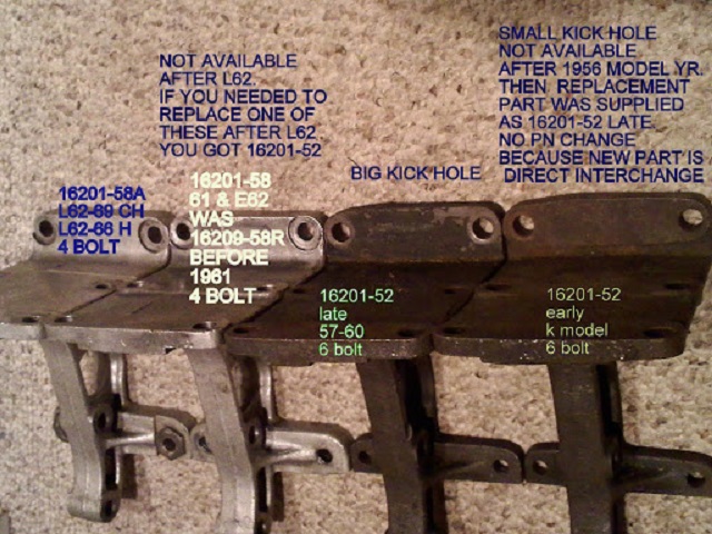
| Rear Motor Mount 36) | |||
| Part# | Year model | Hole for kicker | Notes |
| 16201-52 | 52-60 K Models/XL/XLH/XLCH | ✔ | 4 hole |
| 16201-58 | 61-E62 XLH/XLCH 67-69 XLCH | ✔ | 4 hole |
| 16201-58A | L62-66 XLH/XLCH 67-69 XLCH | ✔ | 4 hole |
| 16203-67 | 67-81 XL/XLH/XLS 70-81 XLCH | ✔ | 2 hole |
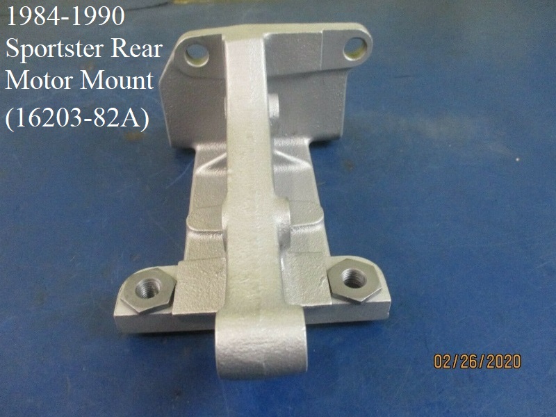
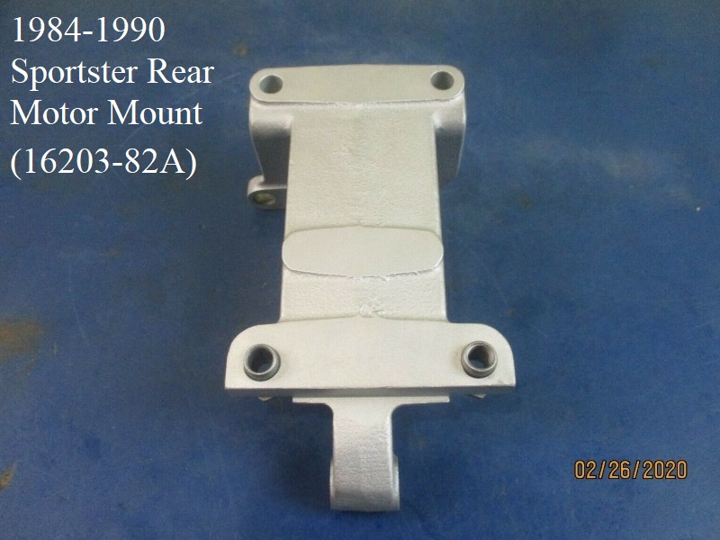
| 16203-82 | 82-83 All | ✘ | 2 hole. Replaced by 16203-82A. Appearance- cast |
| 16203-82A | 84-90 All | ✘ | 2 hole. Replacement for 16203-82. Appearance- billet |
1952-1981
The old rear mounts and the crankcase have 4 holes. 37)
When Harley changed to 2 hole mounts, all they did was knock the front 2 holes off the old mount and later eliminated the 2 front holes in the case.
But the hole spacing stayed the same.
So if you want to use a 4 hole mount on a 2 hole case;
All you have to do, if you should be so lucky to find a steel mount, is saw off the front 2 hole area of the mount.
If you want to use a 2 hole mount on a 4 hole case, you'll have to stick some short bolts in to plug the 2 unused case holes but it should fit just fine. 38)
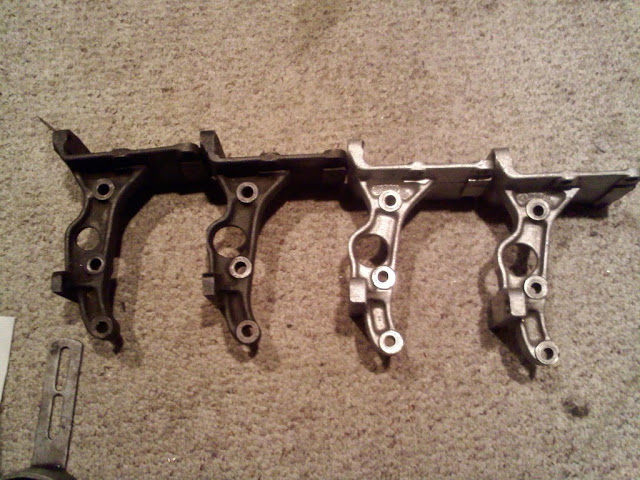
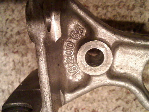
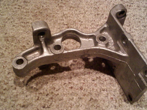
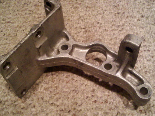
Here are the 4 kick only (4 bolt) rear motor mounts. 39)
From left to right (each pic below):
- 1952-1956 k model (iron).
Note the smaller hole for kicker shaft. The K kicker shaft used a smaller thrust collar than XL. - 1957-E1962 (iron).
- The third is belived to be an XR or R model (aluminium).
It does not use and is not machined for the steel inserts for the lower bolts.
It came with a 60 XLR basket. - L1962-up uses the steel inserts for the lower bolts.
The first 3 use the 2-1/16” long lower bolts(when not using the passenger peg mount).
The late one uses 2-1/4“ long lower bolts (when not using the passenger peg mount).
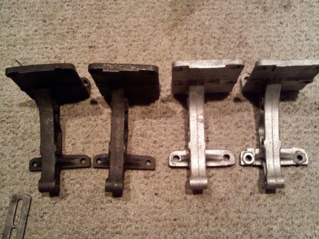
The key to understanding the evolution of these is knowing that 60-down used a 6 bolt lower battery tray and 61-up used a 4 bolt battery tray.
In order to use the 6 bolt battery tray (up to -52b) the mount needs to be milled clear across the upper flange (iron mounts).
When the aluminum was introduced, the battery tray was modified to the 4 bolt -52c.
The two bolts at top flange were no longer incorporated into the tray, so the mounts were not milled.
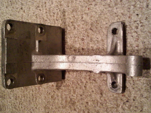
More 16201-58 pics:
This mount could be had in 1960 for $25.70
 44)
44)  45)
45)
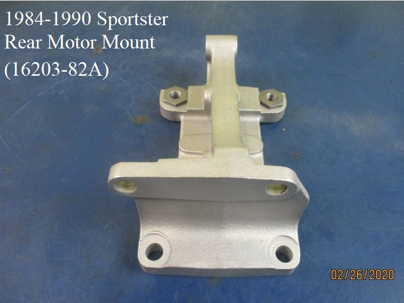
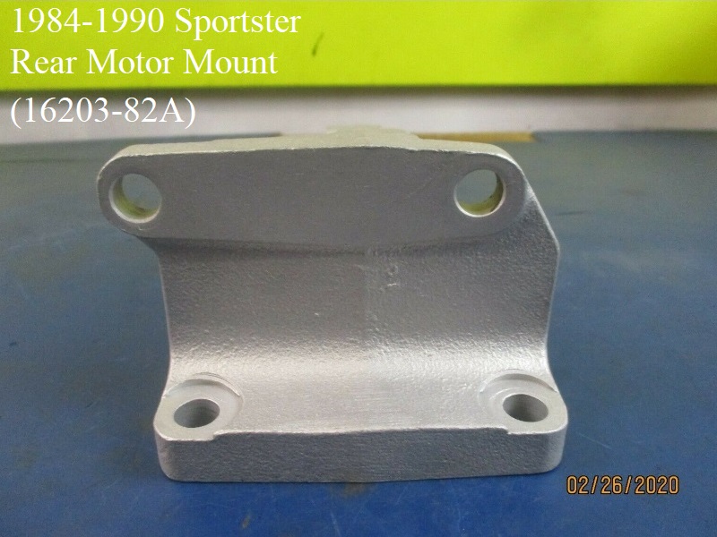
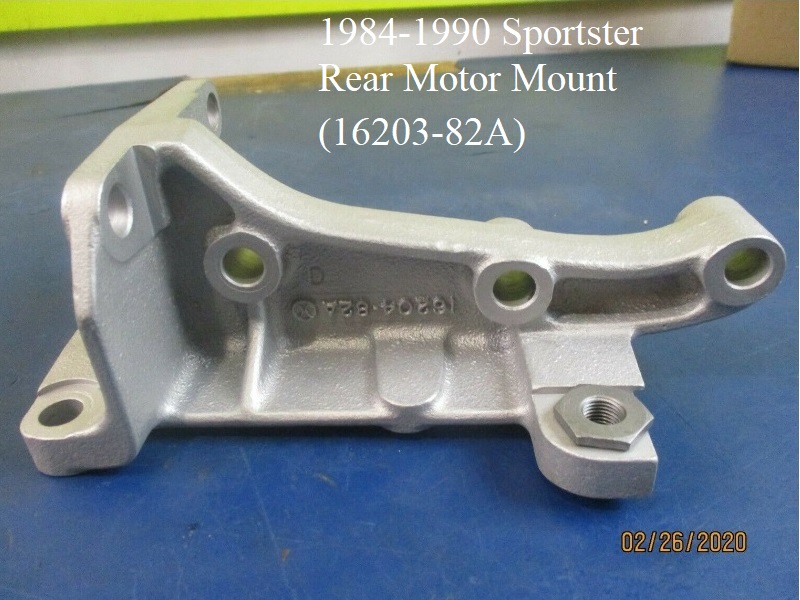
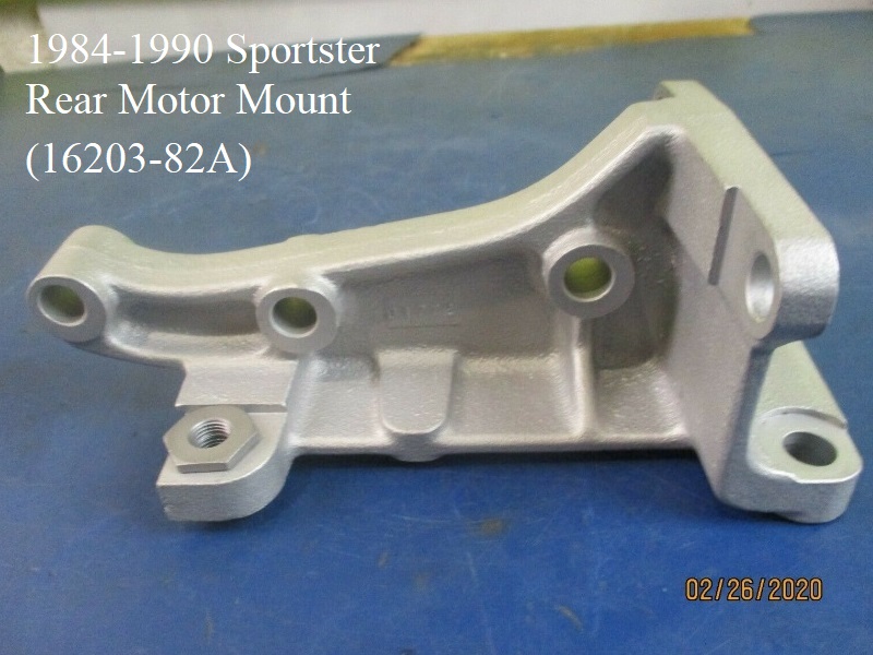
1982-1990
1982-1990 mounts offset the engine 13/32” to the left of the position for pre 1982 engines and don't have the hole in them for the kicker shaft to go through. 48)
1984-1990 Rear Mount:
This mount is made from billet aluminum and was also sold as a replacement for the 82-83 rear motor mount.
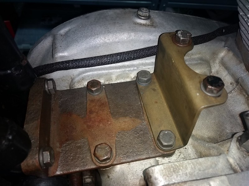
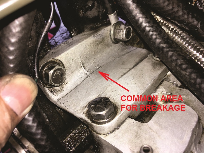
Broken / cracked rear mount
Originally, the rear motor mount was made of steel and had 4 bolts in the top. 55)
Later it was made of aluminum and prone to cracking. The steel mount will never crack.
The first aluminum mount had 4 bolts in the top. Later the mounts had only 2 bolts.
Aluminum mounts are going to crack. If you have a brand new replacement mount in hand right now, it will crack.
Should your mount be a steel one, then it is worth installing. But, the cracks do not present a real problem though.
That is the good news.
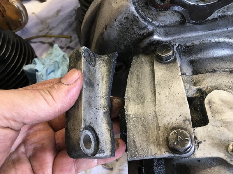
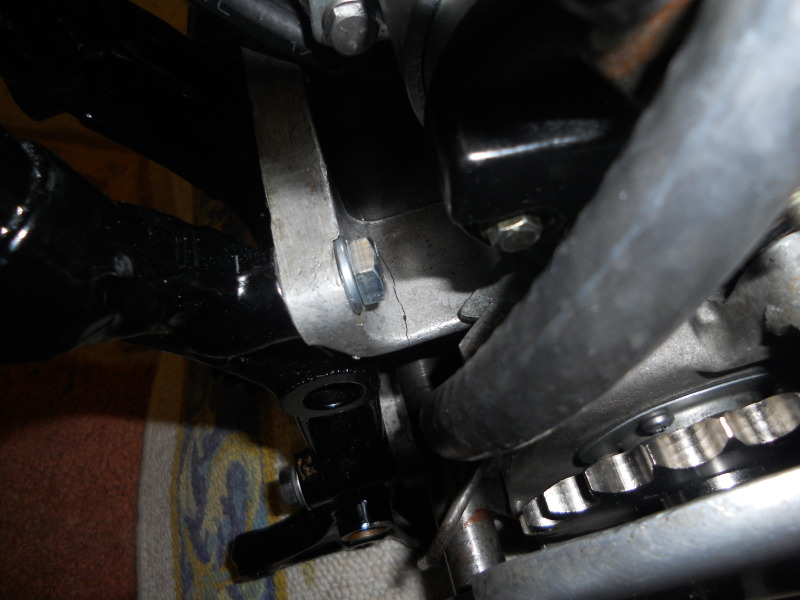
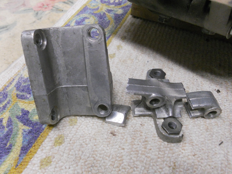
Sometimes the mount cracks all the way across as in the pics below.
Whilst many of them tend to crack, some only crack so far and then stabilize. 56)
Unless it's completely cracked through or flexing like mad, you can run it and monitor whether or not it gets worse.
So it's not necessarily a problem that has to be fixed depending on how badly cracked it is.
However, it does reduce vibration to repair or replace.
And even if the aluminum mounts are installed correctly, they will still crack. They seem to crack worse after welding. 57)
It may be best to score a 57-60 steel mount (a 52-56 k model mount will work too if you ain't got a kickstart) and cut it to mimic the -67 mount.
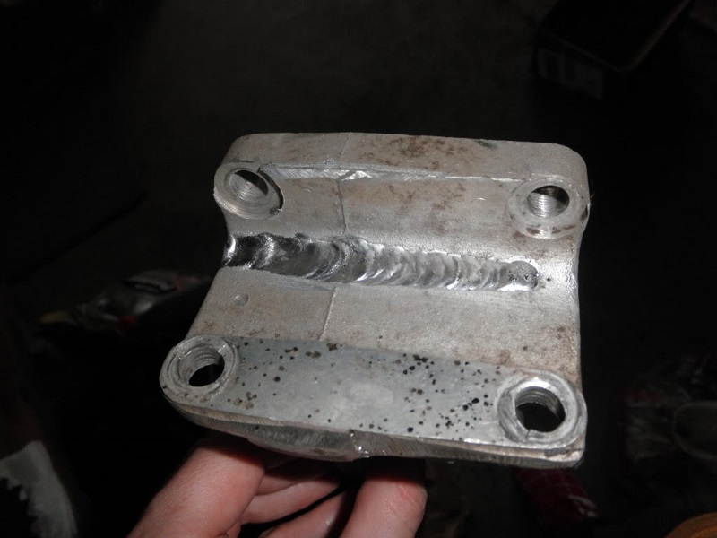
You can try to have the crack welded as in the pics below.
You can also replace it with an aftermarket mount. Pingel has a high reputation as an aftermarket alternative.
See Pingel Rear Motor Mount in the REF section of the Sportsterpedia.
The heavy aftermarket works but it takes up more room and you gotta screw around with the lower oil tank mount if you're working on a 70-78CH.
This one is cracked all the way across.
 58)
58)  59)
59)
This one is only cracked for a small distance.
 60)
60) 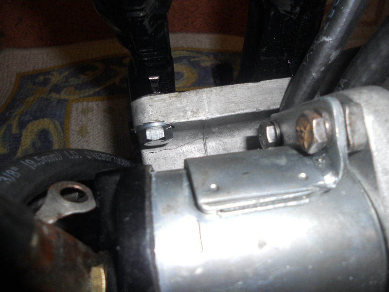 61)
61)
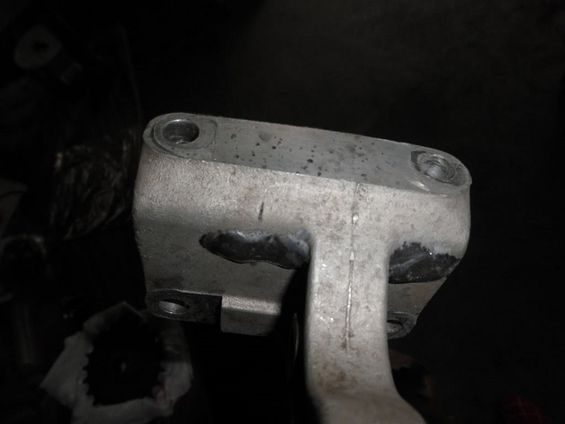
This one from a 68 XLCH has been welded.
Removing the rear mount
To remove the rear mount the engine has to come out of the frame and you generally have to split the cases unless can remove the studs. 64)
If you can remove the studs, splitting of the cases is not required.
Be advised though that these studs are not easy to remove.
They are factory installed into the left side case and it is a good guess that the factory did not want them coming out.
If you are replacing with an aftermarket rear mount such as a Pingel that slides on with the cases together, you can simply cut the old mount off.
Most aluminum mounts will crack and some have road years with the crack without fixing it as you've got like 6 bolts holding the mount to the engine and the frame. 65)
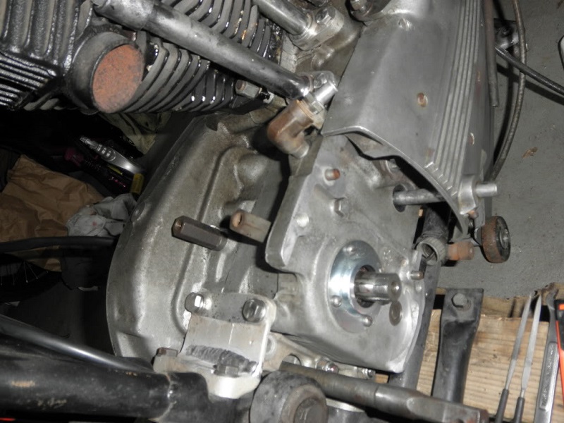
The left case (where the studs are screwed into) comes way back to the end of the primary cover on the left side of the rear mount.
The right case also comes back to the end around the transmission mainshaft.
So that leaves the rear motor mount sitting in the recessed area between the rear projections of both cases.
If you can remove the three studs the mount comes straight out the rear of the engine.
If you cannot get the studs out then you must split the cases.
If the engine is still in the frame, it will be hard to see what is being described.
You can remove the sprocket rightside cover and kick start lever (if equipped) and your view will be much improved.
This is a set of short frame cases but will work to show why the mount won't slide off. 66)
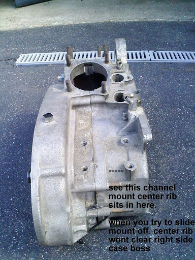 67)
67)
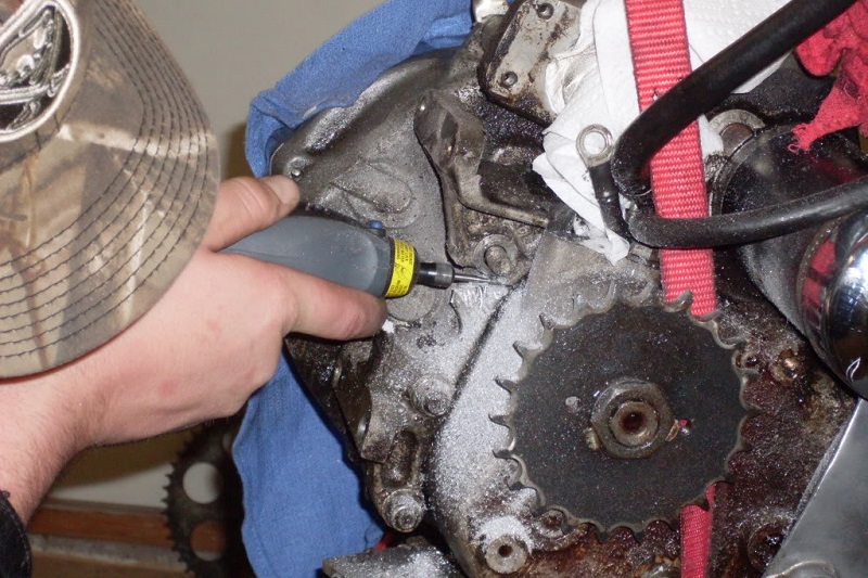
Examples of ways to cut the rear mount off without splitting the cases for a Pingel replacement mount.
Removing the studs
1976 and earlier used studs for both upper and lower holes. These studs were threaded into the left half crankcase and were installed TIGHTLY! 70)
(to the point that removing the studs for a motor mount replacement was never done as a general practice)
The crankcase halves were split to replace a broken mount.
Some have successfully removed the studs but if you screw them up, you are in big trouble, so be careful.
You may have to weld a nut on the end of the stud to get it out. Be sure to have a replacement stud in hand before doing this though.
That's probably why some will say to just run a cracked mount unless it gets too bad.
Although some have had luck with a stud extractor.
Also, you can double nut the stud, heat the area of aluminum around the stud (heat it, Not Cook It). 71)
Then with a box wrench, start to back the stud out. Once it breaks (first 1/2 turn) spray some WD40 on the threads and slowly back out the stud.
Using studs vs bolts on rear mounts
The stud (or bolt) is threaded into an aluminum casting (the case) which is not noted for having great strength. 72)
So the wise move is to use a stud threaded into the case using red Loctite.
The reason is because this is the only time the case threads get disturbed again.
Keep in mind the question, “Just why did the factory do this”?
They did it because there is good engineering reason to use a stud over a bolt.
When you tighten a nut on the stud the nut takes all of the beating and stress as it compresses against the motor mount, not the aluminum case.
If you want to use a bolt, then you should have a Heli-Coil installed in the case first.
Lower Front Mounts
| Sportster year model | Lower front mount (R) | Lower front mount (L) |
| 1957-1977 | 16210-52A (black) | 16213-52A (black) |
| 1978 | 16210-52B | 16213-52B |
| 1979 L1979 adition | 16210-52A (black) | 16213-52A (black) |
| 16210-77 (chrome) | 16213-77 (chrome) | |
| Replaced by 16210-79 (black) and 16213-79 (black) | ||
| 1980-1981 | 16210-79 (black) | 16213-79 (black) |
| 16210-77 (chrome) | 16213-77 (chrome) | |
| 1982-E1984 | 16210-81 (black) | 16213-81 (black) |
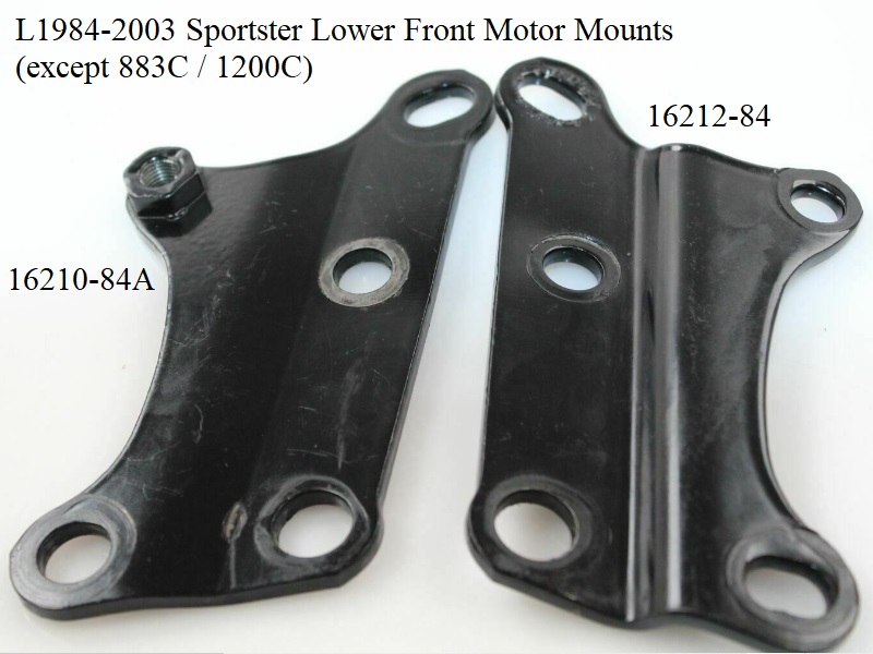
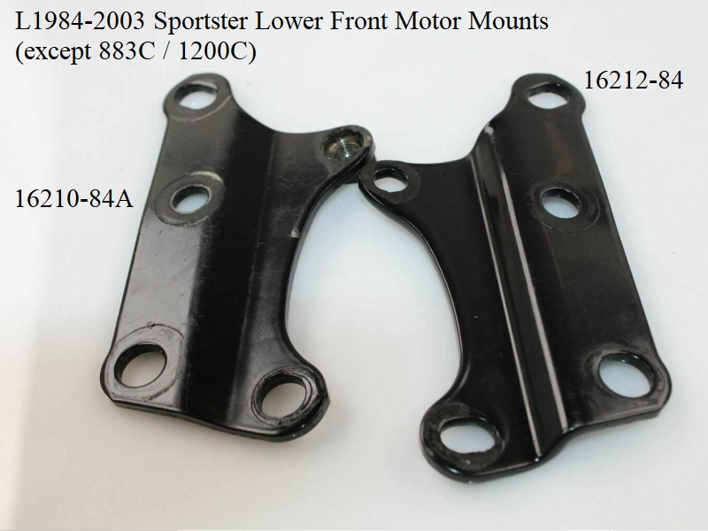
| L1984-1990 | 16210-84 (black) | 16212-84 (black) |
| 1957-1981 style lower front motor mounts. 73) |
 |
| 1982-E1984 lower front motor mounts / filter mount. (left shown) 74) See this page in the Sportsterpedia for building your own filter / motor mount for previous year models. |
|
 |  |
| L1984-2003 style lower front motor mounts. 75) | |
 |  |
Specifics behind the assembly
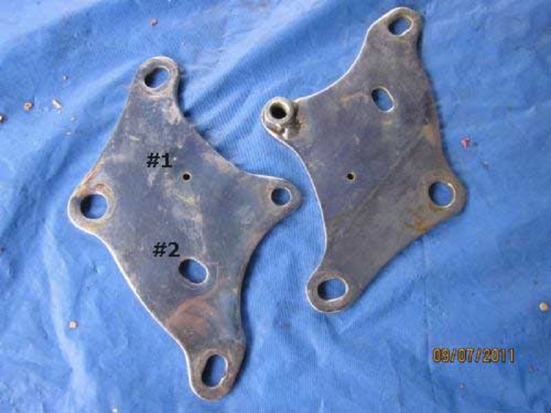
- The key to what the factory did is the 4 holes in the plates (2 for plate to case & 2 for plate to frame) 76)
- Let's look at case holes in the plates 1st.
The top hole (this is the one that has the nut welded on the right side plate) is round and fits closely to bolt diameter.
When this bolt gets put together, the plates are located to the case cause the plate hole isn't sloppy on the bolt.
This is the “master” bolt. (although the plate can rotate using the bolt as an axle until you put in the lower case bolt). - Now look at the plate hole for the lower case bolt.
Its slotted in a way that the plate can rotate about the upper case bolt even when the lower bolt get put in.
This rotary play allows the plates to rotate so the upper frame plate bolt holes in them can line up to the upper holes in frame. - Now these upper frame bolt holes are slotted in the plate too (forward to back).
This is so the bolt will pass thru if different bikes have slightly different frame to motor distances.
But when this bolt gets put in, because of the direction of it's slot, the plates no longer can rotate.
So what you got now is a setup that has the ability to assemble to a big difference in motor / frame alignment, but still not be sloppy. - The last bolt goes thru a big round plate hole. It don't have anything to do with alignment.
The hole is big and round so the last bolt will align no matter how the 1st 3 fit. - What the grooves in the hardened washers do is bite into the face of the plates over the slots and the big over sized lower frame plate hole.
(hence nicknamed “Biter Washers”)
This stops the possibility of the plates sliding in those slots during operation.
The grooves lock the plates to the bolts (6 slots / big holes, 6 grooved washers with the grooves against plates).
Order of bolt / washer installation
The washers have concentric ridges on one side only (affectionately known as biter washers).
The hardened washers described below are the biter washers. 77)
The gripper side of each washer goes toward it's corresponding plate.
On 57-76 models, all the lower front mount bolts install from the left side. 78)
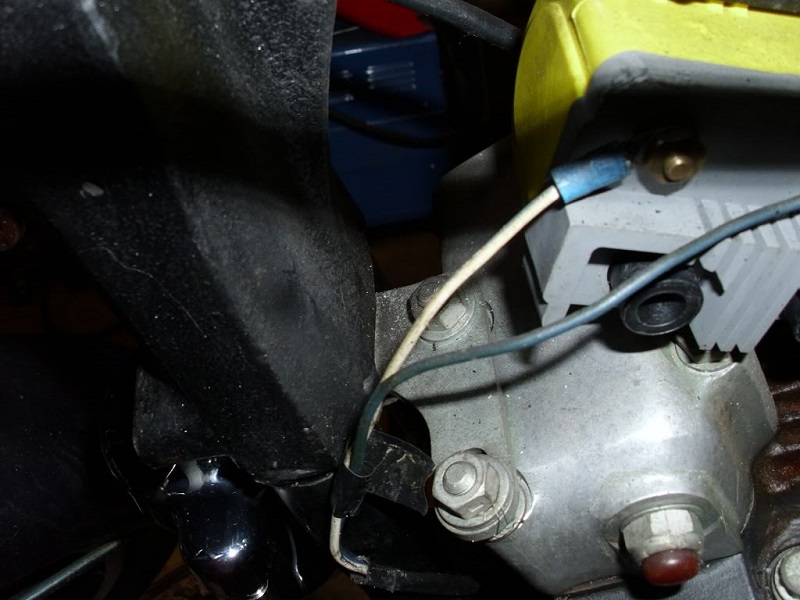
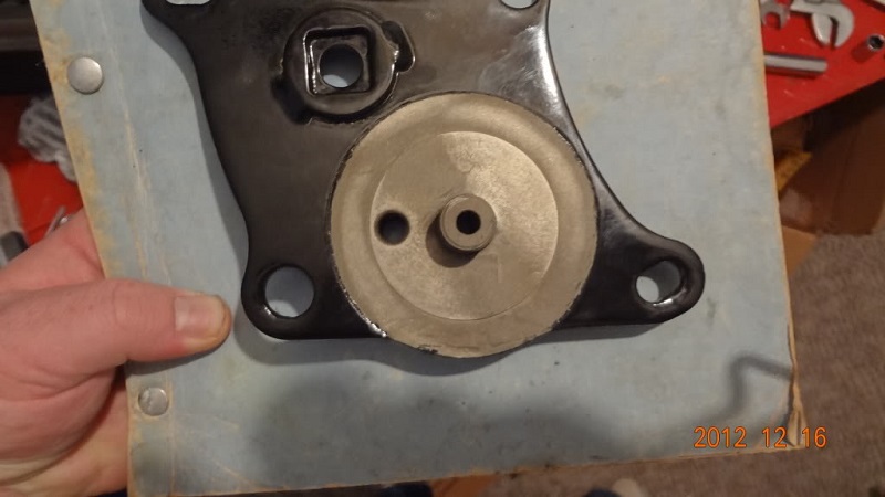
On 77-85 models with the gerotor oil pump, the bolts install from the left side with the exception of the bottom rear bolt that installs into the right side.
(The bolt head and washer takes up less space than the bolt end, washer and nut. So that leaves more clearance for the green wire/nut from the oil switch.)
- There are five of the hardened washers required for the front motor mounts 76< motors and six for 77-up motors.
- There are two motor mount plates.
- There are 4 motor mount bolts. Two we will call front upper and lower. The other two we will refer to as rear upper and lower bolts.
- Front upper bolt:
- Install a hardened washer against the head of the bolt.
- Slip bolt through upper hole in front left engine plate.
- Slip bolt through frame.
- Install spacer on bolt.
- Install hardened washer.
- Install right engine plate. (Right side engine plate sits inside the frame)
- Slip bolt through frame on right side.
- Install nut and flat washer.
- Front lower bolt:
- Done the same as above.
- Rear lower bolt:
- Done the same as above, except:
- No spacer is used. Run the bolt through the crankcase.
- The right side engine plate rests against the crankcase.
- Hardened washer is installed on bolt.
- Install nut and flat washer.
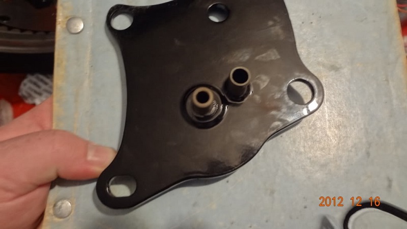
- Rear upper bolt:
- This is the odd one. Install a lock washer against the head of the bolt.
- Insert bolt into left engine plate.
- Run bolt through engine crankcase.
- This bolt will thread into the welded on nut sitting on the left side engine plate.

Top Mounts
1957-1976 top mount
Sub Documents
Note:
There are no instructions or mention of how to attach these mounts in the FSMs other than basic statements to the effect of “install the bolts”.
Dr Dick's instructions below detail how the washers for the straddle mount should reside UNDER the bracket instead of on top under the bolt head.
And accordingly, the washers being on top under the bolt head is responsible (at least in part) for cracked heads at the threaded mounting holes for this mount.
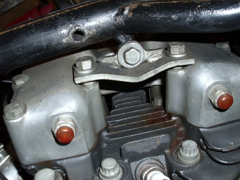
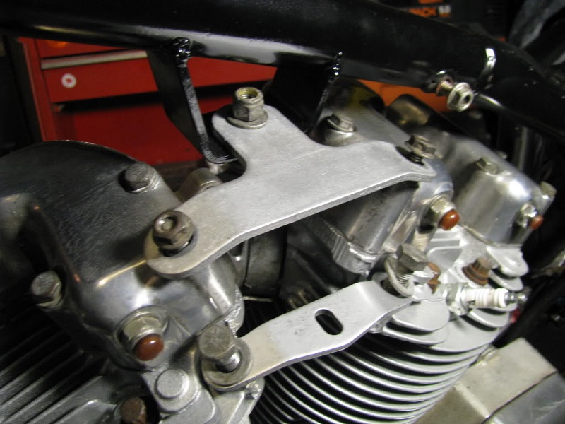
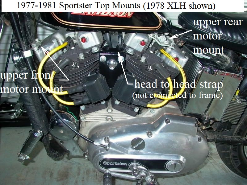
Head to head straddle mount (or center mount or head steady):
There is only the one upper motor mount assembly from 57-76 consisting of a support brace between the heads and a cross mount from there to the frame.
Support brace (straddle mount) is engineered to deal with production tolerances, most owner created misalignments and is the first thing to assemble on top. 79) 80)
The straddle bracket (16250-57) mounts from head to head and a cross brace bolts to the straddle and ties back to the frame.
The straddle bracket changed in L1971 and again in 1979 but the part number stayed the same.
There were two different cross braces from 1957-1976. See the parts list below for year models used.
| 1957-1967 Top Mount Parts List 81) | |||
| Year Model | Description | Part# | Notes |
| 1957-E1971 XL, XLH, XLC, XLCH | Head Straddle | 16250-57 | Original bracket. |
| L1971-1976 | Head Straddle | 16250-57 | Relief machined on the motor side of the bracket. This version was sold for 1957-1976 models. |
| 1957-1964 XL, XLH 1959-1964 XLCH | Cross Brace | 69031-57 | Original XL, XLH bracket. |
| 1958 XLC, XLCH 1965-1976 XLH, XLCH | Cross Brace | 16251-58 | Has 2 holes for horn bracket on the end. |
| 1957-1976 | Straddle to Head Bolt (2) | 4618W | 7/16“ x 20 x 7/8” |
| 1957 XL | Straddle to Head Washer (2) | 6505W | 7/16“ x 1” x 1/8“ |
| 1958-1976 XL, XLH, XLC, XLCH | Straddle to Head Washer (2) | 6495 6495 HW | 29/64” x 15/16“ x 1/8” |
| 1957-1971 XL, XLH, XLC, XLCH | Straddle to Cross Brace Bolt | 4336W | 3/8“ x 24 x 1-1/8” Hex Head |
| 1972-1976 XLH, XLCH | Horn Bracket | 69129-72A | Has 3/8“ x 24 welded (straddle to cross brace) stud. |
| 1957-1976 XL, XLH, XLC, XLCH | Straddle to Cross Brace Nut | 7775 | 3/8” x 24 Flexlock |
| 1957-1971 XL, XLH, XLC, XLCH | Straddle to Cross Brace Washer (underneath straddle) | 6417 6417W | 3/8“ x 1-1/8” x 1/4“ |
| 1957-E1972 | Cross Brace to Frame Bolt | 16865-52 | 7/16” x 20 x 7/8“ (13/16” Hex Head) (w/ cotter pin hole, for XR) |
| L1972-1976 | Cross Brace to Frame Bolt | 4726 | 7/16“ x 20 x 1-1/2”, (5/8“ Hex Head) |
| 1957-1976 | Cross Brace to Frame Washer | 6522B 6522HB | 29/64” x 1-1/8“ x 5/32” (.156“) |
| 1957-1976 | Cross Brace to Frame Washer | 6524 | 29/64” x 1-1/8“ x 1/64” (.016“) |
| 1957-1976 | Cross Brace to Frame Washer | 6521 6521W | 29/64” x 1-1/8“ x 3/32” (.094“) |
| 1957-1976 XL, XLH, XLC, XLCH | Cross Brace to Frame Nut | 7825 | 7/16” x 20 Flexlock |
Factory Assembly per Dr Dick
There are three straddle mounts from 1957-1985;
- 1957-E1971 (factory fitted with the -57 head castings).
These were straight along the edge that faces the rocker boxes.
You shouldn't use this mount on any other head casting with out checking for clearance. - L1971-1976 factory fitment.
These were shaped like “Ben Franklin's eye glasses”.
This part can be used on all 57-76 no matter what heads you are running. - 1977-1985. All 3 holes are slotted.
This should not be used on 76< frames.


ASSEMBLY:
- Assemble the straddle to the heads:
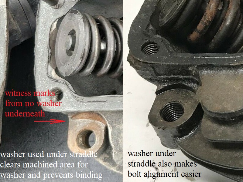
- A 1/8“ thick 1” dia. washer goes BETWEEN each head and the bottom straddle mount (1 on each end of the straddle mount).
Then the bolts (7/16“-20 X 7/8” bolts 5/8“ hex size) get put in with no washers on the bolts (between the bolt heads and straddle).
The head is machined where this washer sits. The washer raises the strap above any unmachined nubs around the washer seat. 86)
It keeps interference at bay. If you look at the different strap profiles, you see the 1000 mount is also relived for nub clearance.
The 900 strap is not relived and when you see heads that are broke at the tapped hole, you will see most are 900.
Busting the mount lugs is because the washers are put on top smashing the strap into the nubs and splitting the head. - No washer between the bolt and the top of straddle mount. Both the versions of straddle mounts get assembled the same.
- The cross mount to straddle;
- Gets placed under the straddle mount (all years)
- Gets bolted with no washers (58-64).
- 57 gets the choke mount placed under the cross mount.
- 65-76 uses the stud in the horn mount instead of the bolt.
- 66 gets the choke lever assembly added to top side of straddle.
- Install Flexloc or Nyloc nut.
- The cross mount to frame;
- You will notice there is a giant space between the frame and the cross mount.
- The cross mount and the frame surfaces will be parallel. If they aren't then something is amiss.
- Select the correct pair of washers to fill 'your' space between the cross mount and the frame. This will take two of the three washers.
- Take the remaining washer and slip it over the bolt. Both get slid in from the bottom, thru the cross mount, washer stack, and frame bracket with the nut on top.
- At this point you got:
- Three 1-1/8” OD washers (two thick) and (one thin).
- A Flexloc or Nyloc nut
- A 7/16“x20 bolt, either 13/16” hex head 57-E72 (this bolt may be crossed drilled for a cotter pin/safety wire for R model use), or 5/8“ hex L72-76.
This bolt eventually goes in from bottom with either a castle nut or nyloc depending on year.- The bolt with the 13/16” thin hex got 1 of the 2 thicker washers slipped on then these 2 items went from the bottom thru the cross mount.
Then the other thick wash, then thin washer (these are slid between the top of cross mount and the bottom of the frame mount), then frame mount. - 73-up used a regular 7/16“x20 bolt, not 13/16” hex, instead.
- Now the nut on top.
1977-1985 top mounts
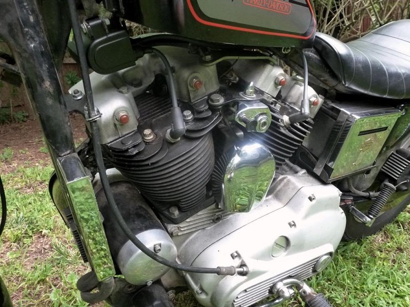
- 1977-1981 top frame mount locations:
- The center motor mount and frame bracket from previous years was deleted for these models years.
The head to head strap was still used, just not attached to the frame there.
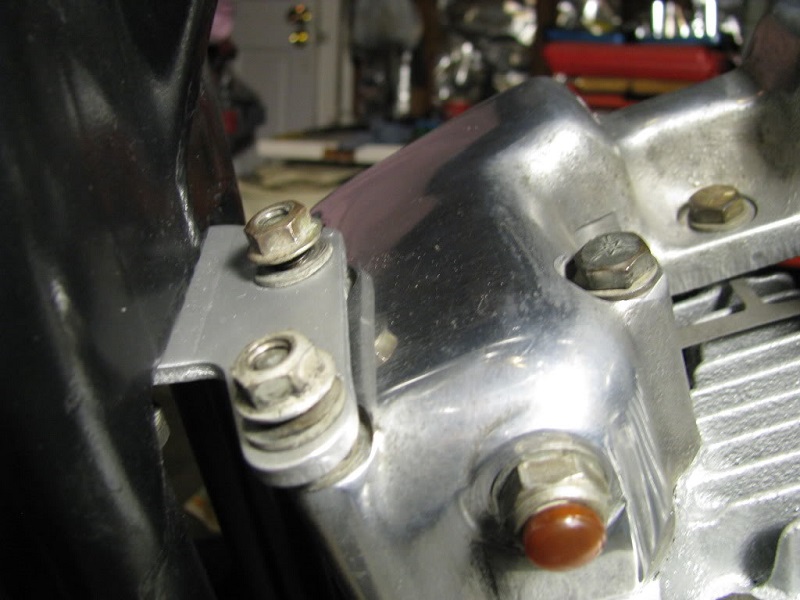
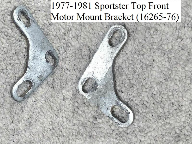
There are two motor to frame mounts on the top; an upper front mount to under the neck and an upper rear mount below the backbone. - The top front bracket (16265-76) is an “L” shaped piece with 3 slotted mounting holes.
It attaches to the front rocker box with 2 rocker cover mounting studs and also underneath the frame neck (by a 5/16“ x 18 bolt that screws in upwards).
If the front of the frame is stock, you should see the threaded hole by looking up with a flashlight. It should be tapped for 5/16”-18 threads.
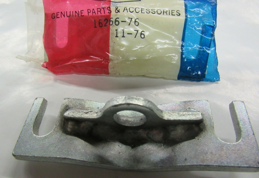
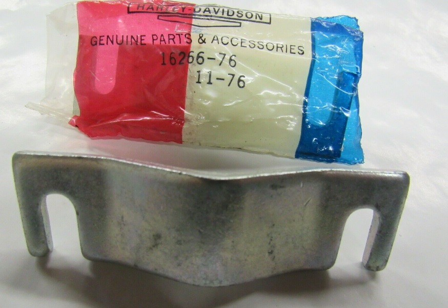
The upper front mount can be tedious to install. Easiest to install while installing the rocker cover while things are loose. 87) 88) - The top rear bracket (16266-76) has a hole in the top center at the frame mount and two open slots on the bottom to rocker box studs.
The same bracket is used from 1977-1981. The part that's different between 77 and 78-81 models is the fasteners used.
The 77 upper rear motor mount is attached to the rear rocker box with bolts where 78-81 models were attached with dual threaded studs.
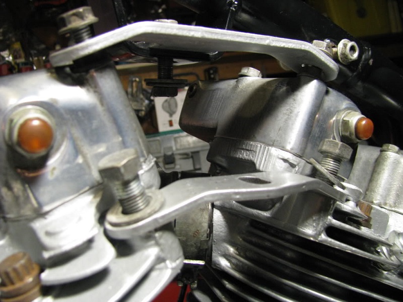
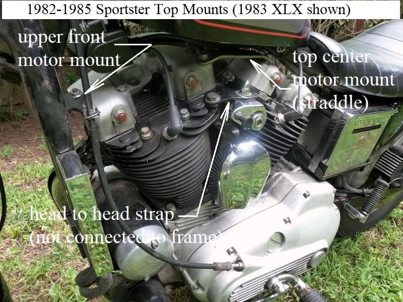
- 1982-1985 top frame mount locations:
The center motor mount was added back for these model years. However, the straddle mount system (between the heads) to the frame was redesigned.
There are two motor to frame mounts on the top; An upper front mount off the front rocker box to under the neck,
And a center mount bracket that sits between and attaches to both rocker boxes instead of the heads.
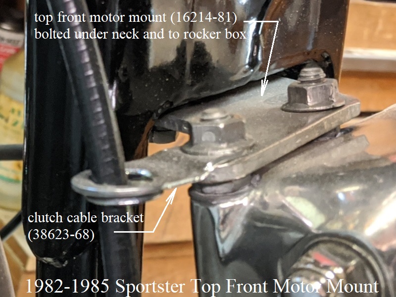
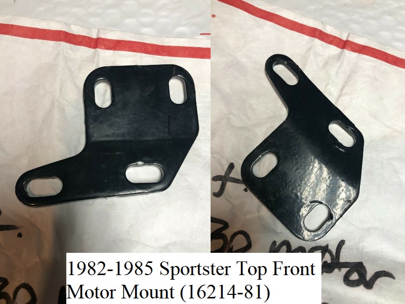
The head to head strap was still used, just not attached to the frame there.- 1982-1985 top front bracket (16214-81) is a wide “L” shaped piece with 4 mounting holes.
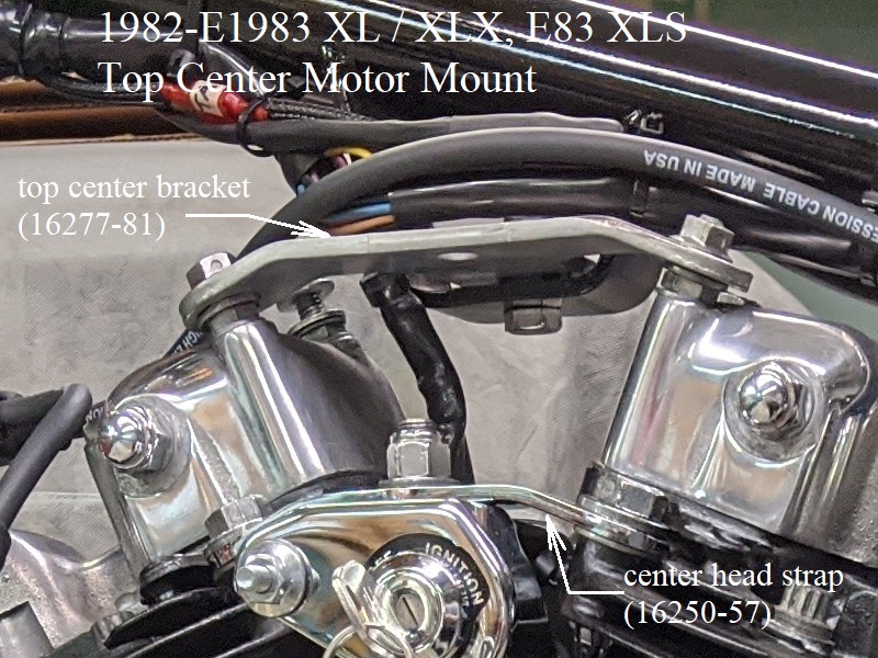
It attaches to the front rocker box with 2 rocker cover mounting studs and also underneath the frame neck (with two 5/16“ x 18 bolts that screw in upwards). - 1982-E1983 XL/XLX, E83 XLS top center bracket (16277-81) is a “T” shaped plate with 3 mounting holes.
- 1982 XLS/E1983 XL top center bracket (61021-82) is 2 piece with a “T” shaped plate with a welded extension and an interlocking straight bracket.
- L1983-1985 XL/XLX/XLS top center bracket (16277-81A) is a “T” shaped plate with 3 mounting holes and an additional hole in the middle.
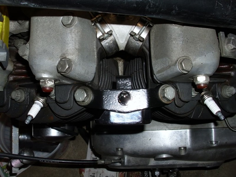
- 1977-1985 head strap:
The center head strap (16250-57) between the heads is black except for 79-E81 XLS which is chrome (16276-79).
It is not an actual motor mount but does keep structural integrity between the heads although it doesn't attach to the frame.
See details below.
Assembly
The order of installation written in the sections below can be adjust based on personal preference or ease of installation.
Use your own judgement.
Don't forget to shim as needed. The shimming is very important (for both the upper front and upper rear mounts). 91)
Shim these wherever so that when you tighten the fasteners there is no stress on any of the adjacent parts. Otherwise the mounts will break from vibration.
Read more about shims at the top of this page.
1977 to 1981 Sportsters
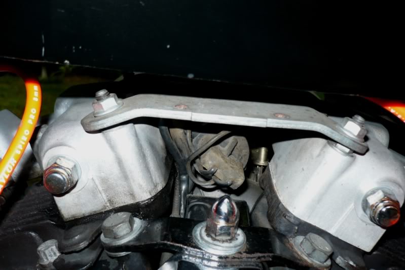
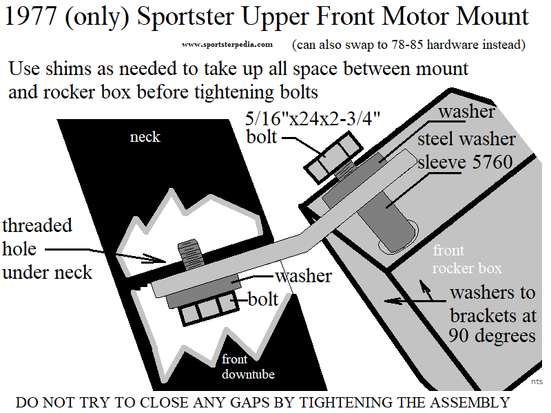
- 1977 (only) Top Front Mount:
- Install the mount assembly into the front two rocker box holes.
Two 5/16” x 24 x 2-3/4“ bolts (4725) each with a 1/16” washer (6316HW) under the head run thru the motor mount bracket.
A metal spacer sleeve (5760) goes on each bolt under the bracket to the mounting holes in the rocker box.
These bolts are used just for the motor mounts and are 1/2“ longer than the regular mounting bolts for the rocker box.
Do not tighten or snug the bolts just yet. - Install the mounting bracket to the frame neck and tighten.
The mount attaches under the frame neck using a 5/16” x 18 x 7/8“ bolt (3991), lockwasher (7041) and a 1/16” thick washer (6702) in that order. - Shim if needed. Click Here to read more on shims at the top of this page.
Check to make sure there is no free space left under the mount (between the mount and rocker box) before tightening.
Don't allow any of the mounts to be “pulled” into position by tightening the bolts. 92)
- With the bolts finger tight and “zero space” left over, tighten the bolts on top of the bracket.
- You can also swap to the 78-81 type fasteners as the same upper front motor mount is used with dual threaded studs into the rocker box instead of longer bolts.
The thread TPI and length into the rocker box holes is the same for both the bolts and the studs.
See below for more information.
- 1977 (only) Top Rear Mount:
- Install bolt assembly through frame sleeve and top hole in the mount and tighten.
The rear top mount bolts to the frame with a 5/16” x 18 x 2-1/2“ bolt (4068). The bolt has a 7/8” OD x 5/64“ thick washer (6333) slid on under the head.
The bolt runs thru the sleeve welded to the frame from the right side with a 11/16” OD x 1/16“ thick washer (6702) added against the left side of the frame sleeve.
The bolt then runs through the hole in the top of the mount.
A 11/16” OD x 1/16“ thick washer (6702) is added against the mount with a 5/16” x 18 locknut (7710W) on the end.
You can also add more washers to adjust (L-R) shifting of the mount or bolt length (mount has slots instead of holes at the rocker box). - Install the top rear mount assembly on the rocker box but leave it loose.
Two 5/16“ x 24 x 2-3/4” bolts (4725) each with a 1/16“ washer (6316HW) under the head run thru the motor mount bracket.
The mounting holes in the rocker box are recessed to where the mount will not touch the top of them.
Therefore to keep from breaking the mount, washers should be installed on the bolts under the mount to keep the mount off the rocker box.
Then the bolts go into the rocker box making up that assembly. - Shim if needed. Click Here to read more on shims at the top of this page.
Check to make sure there is no free space left under the mount (between the mount and rocker box) before tightening.
Don't allow any of the mounts to be “pulled” into position by tightening the bolts. 93)
- With the bolts finger tight and “zero space” left over, tighten the nuts on top of the bracket.
- You can also swap to the 78-81 type fasteners as the same upper front motor mount is used with dual threaded studs into the rocker box instead of longer bolts.
- The thread TPI and length into the rocker box holes is the same for both the bolts and the studs.
See below for more information.
- 1978-1981 Top Front Mount:
- Install the studs into the front two rocker box holes.
Two studs, (3412 except 79 XLS) (3417 for 79 XLS), install in the front rocker box to head holes instead of the normal bolts there.
A 1/16” thick washer, (6316HW except 79 XLS) (6002 for 79 XLS), goes under each stud before installing into the rocker box. - Place the mounting bracket over the studs. Per the parts books, the mounting bracket goes on top of the stud with no washer between the stud and bracket.
See below. - Install and tighten the upper front mount to the frame.
The mount attaches under the frame neck using a 5/16“ x 18 x 7/8” bolt (3991), lockwasher (7041) and a 1/16“ thick washer (6702) under the bolt head. - Shim if needed. Click Here to read more on shims at the top of this page. The built in stud hex nuts are faced (machined flat where the bracket sits) for a flush fit.
Check to make sure there is no free space left under the mount (between the mount and rocker box) before tightening.
Don't allow any of the mounts to be “pulled” into position by tightening the nuts/bolts. 94)
- With “zero free space” left over, install a 5/16” x 18 x 1/4“ locknut (7740) and 1/16” washer on top of the each stud and tighten the assembly.
The length of the stud above it's (built in) hex nut is 1/2.
The top of the stud should end up no shorter than flush to the top of the nut with the assembly installed and torqued.
- 1977-1981 Head Strap:
- 1978-1981 Top Rear Mount:
- Install top rear mount on the rocker stud assembly but leave it loose.
A threaded stud bolts to each rocker box under each motor mount bracket hole (slot) with a 1/16“ thick washer between the stud (nut) and rocker box.
The mounting holes in the rocker box are recessed to where the mount will not touch the top of them.
Therefore to keep from breaking the mount, washers should be installed on the bolts under the mount to keep the mount off the rocker box.
Stud: (3412, zinc) used for 78-81 XL, XLCH and 81 XLS. Stud (3417, black) used for 79-80 XLS. Both are the same size.
Another washer can be placed on top of each stud (nut) if needed (raising the bracket off the rocker box), then the mounting bracket, a 1/16” washer and a nut. - Install bolt assembly through frame sleeve and top hole in the mount and tighten.
The rear top mount bolts to the frame with a 5/16“ x 18 x 2-1/2” bolt (4068). The bolt has a 7/8“ OD x 5/64” thick washer (6333) slid on under the head.
The bolt runs thru the sleeve welded to the frame from the right side with a 11/16“ OD x 1/16” thick washer (6702) added against the left side of the frame sleeve.
The bolt then runs through the hole in the top of the mount.
A 11/16“ OD x 1/16” thick washer (6702) is added against the mount with a 5/16“ x 18 locknut (7710W) on the end.
You can also add more washers to adjust (L-R) shifting of the mount or bolt length (mount has slots instead of holes at the rocker box). - Shim if needed. Click Here to read more on shims at the top of this page.
Check to make sure there is no free space left under the mount (between the mount and rocker box) before tightening.
Don't allow any of the mounts to be “pulled” into position by tightening the bolts. 95)
- With all the bolts finger tight and “zero space” left over, tighten the remaining nuts.
Ensure the space didn't change under the bottom two bolts after tighten them.
The length of the stud above it's (built in) hex nut is 1/2”.
The top of the stud should end up no shorter than flush to the final nut on top with the assembly installed and torqued.
1982-1985 Sportsters
- 1982-1985 Top Front Mount:
- Install the studs into the front two rocker box holes.
Two studs, (3412) install in the front rocker box to head holes instead of the normal bolts there.
A 1/16“ thick washer, (6316HW) goes under each stud before installing into the rocker box.- Place the mounting bracket over the studs. Per the parts books, the mounting bracket goes on top of the stud with no washer between the stud and bracket.
See below. - Install and tighten the upper front mount to the frame.
The mount attaches under the frame neck using (2) 5/16” x 18 x 1-1/4“ bolts (2871W) and 5/64” thick washers (6333). - Shim if needed. Click Here to read more on shims at the top of this page.
The built in stud hex nuts are faced (machined flat where the bracket sits) for a flush fit.
Check to make sure there is no free space left under the mount (between the mount and rocker box) before tightening.
Don't allow any of the mounts to be “pulled” into position by tightening the bolts. 96)
- With “zero free space” left over, install a 5/16“ x 18 x 9/32” locknut (7531) and 1/16“ washer on top of the each stud and tighten the assembly.
The length of the stud above it's (built in) hex nut is 1/2”.
The top of the stud should end up no shorter than flush to the top of the nut with the assembly installed and torqued.
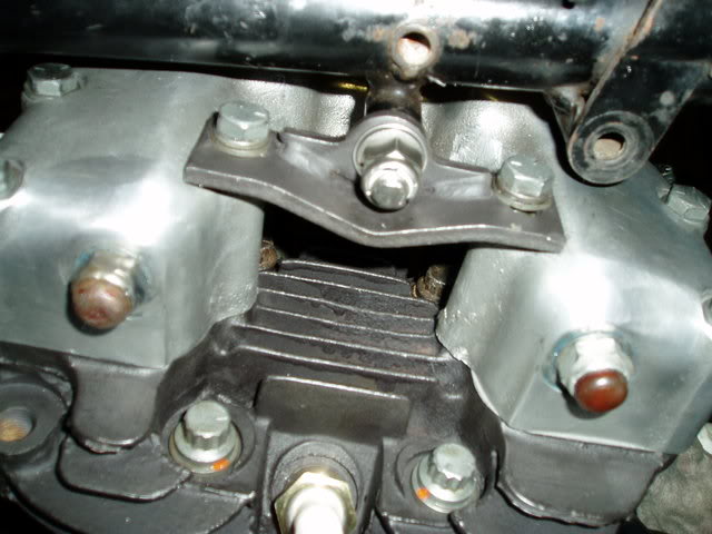
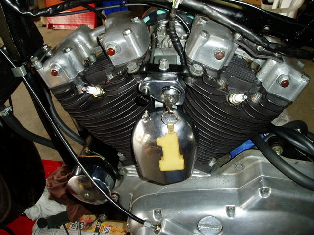
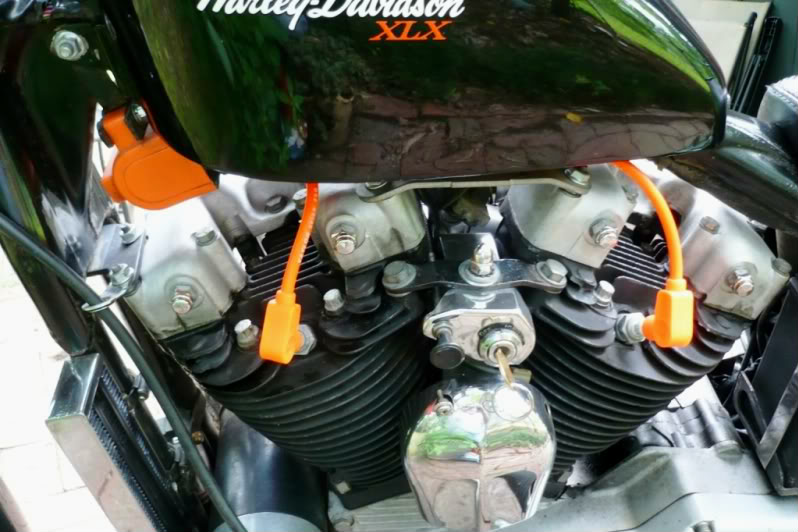
Pics of Top Mounts for 1977-1985 Models

Pics of Top Mount Locations for 1977-1985 Models (as mounted)
The pics below are specifically for showing the location / orientation of the mounts. Washer count and placement may vary on used motors.