Table of Contents

IH: Oiling & Lubrication - Sub-03G
57-76 Oil Pump Damage and Repair
See also bustert's videos on YouTube:
- Youtube video on an oil feed seal. Far easier and non destructive. 1)
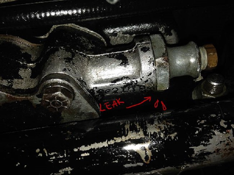
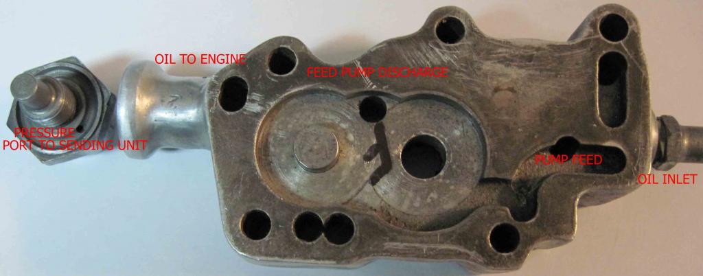
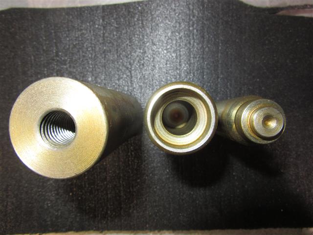
Leaking Around Oil Pressure Switch Connection
The threading for the pressure switch nipple is not a tapered pipe thread. 2)
It's a 15/32“-24. An oddball size, but that's what it is.
Cracked pumps are actually common. It's easy to over tighten the switch fitting.
You're tightening a steel fitting that has a less than 1/2” thread into aluminum with a large 1“ wrench.
It's not the thread that seals the oil, it's the flat surface of the pump body against the flat surface of the fitting that does that.
It only needs to be snug.
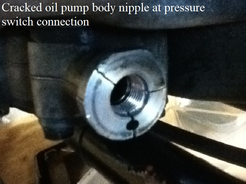
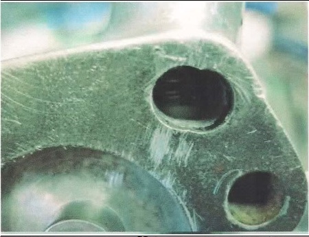
If you have a leak from the oil pressure switch nipple area, 99% of the time it is a cracked body. 3)
Pull the 1” hex nut and look for a crack on the flat face of the body at 6:00.
The crack will pass from the center hole, thru the small hole to outside of the body.
Fixing Leaky Pump from Sit Sumping
Oil getting into the crankcase from the act of the bike just sitting still is a common occurrence. 6)
It is commonly blamed on the oil pump check valve (ball) allowing oil from the oil tank to seep past it and flood the engine.
But it can also be coming in from the clearances of the gears as well as from the shaft seal between the feed and return gears.
Testing the oil pump for leaks
You could apply oil via the oil tank to the inlet nipple on an installed pump and observe if oil is leaking through the check into the discharge hole to the engine.
There is no reason to take anything but the front fitting of the pump off.
If you get nothing in the catch can obviously there isn't any oil getting to the spring side of check.
If there is, that can be from the return / vent line back feeding into the the camcase and collecting in the pick-up cavity.
From there it can drain down behind the check and leak into the can.
Or, it can be a leaking check on the feed side.
How do you pinpoint which one?
You block off the vent and return lines so the feed line becomes the only way for oil to leave the tank.
No oil in catch can now = a good check valve (ball).
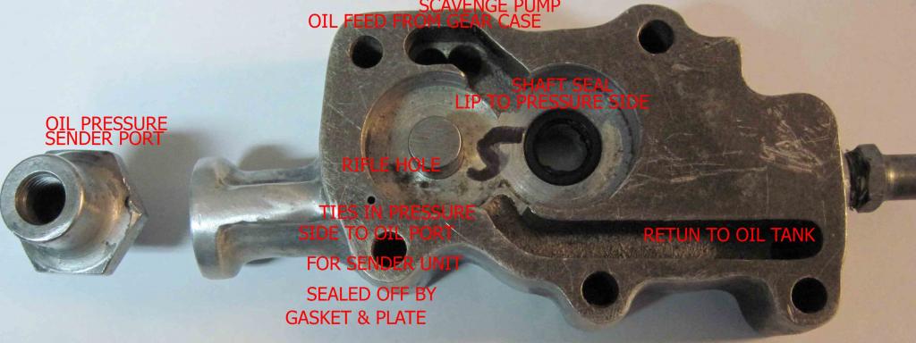
Another way to check the system would be to remove the pump, dis-assemble it and blank it off. 7)
Then you could pull a vacuum from the inlet nipple to see it the system is functional.
You could apply oil via a container to the nipple on a ready, install the pump and observe.
Then you can see if oil is leaking through the discharge hole to the engine or out the return to tank hole.
This would indicate ball or shaft. Just add oil until it leaks, easy to calculate hydrostatic head to know at what pressure it will leak at.
It is better to know the problem than to throw money at it.
Check Ball Seat Repair
When it comes to a 'fix' for a leaky check ball; 8)
On the human side:
The drive to better the way something works stands on its own and it does bring rewards (usually thru a string of failures).
Those failures will illustrate areas where we didn't think of something and it's thru those new understandings that we actually can make improvements.
Old man Honda said “There is no success for those who can not tolerate failure.”
On the mechanical side:
If your check doesn't close, it can be a pita.
That pain is nothing to the pain it causes when it doesn't open. For when it doesn't open, oil won't flow into your engine.
The ball is held to the seat by a spring.
Increasing the spring force increases the pressure the pump needs to produce to open it to oil the engine.
(whether from more preload, or stretching the spring, or using the -72 spring in a -62 pump)
Likewise, decreasing the area inscribed by the minor diameter of seat decreases the amount of ball area the pump pressure gets to act upon.
The force of pressure acts over the area where its applied, thus it's the product of the two that overcomes the spring force holding the valve closed.
(decreasing the area is tantamount to increasing spring force)
When you're playing around with the check ball / seat, you're playing with your heart valve here.
The only question on how to go about a fix is; can you accept your failures?
Below are methods both tried and used in the effort to stop oil leaking into the motor through the oil pump.
The FSM suggests the tapping method with a new check ball.
Others have been discussed and used by members of the XLForum and are listed as such.
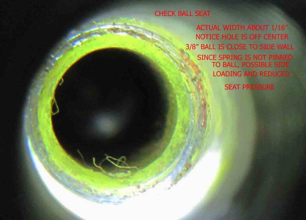
Over time, the ball will actually touch the shoulder and not seal on the bevel.
A little indigo paste on the ball will tell if this is happening.
The tapping method:
The traditional “tapping” method is described in the FSM. 9)
Using a light, inspect the valve (ball) seat in the pump body for pits and for dirty condition.
A small particle of foreign matter lodged on the valve (ball) seat will prevent the check valve ball from seating.
If the seat is only slightly damaged, place a new ball on the seat and use a drift against the ball and to lightly tap against the seat.
Then install a new spring along with the new ball. 10)
Basically, just stick the ball in the hole, push it tight against the seat with a drift and then give it a few light whacks with a small hammer.
The aluminum housing is not as fragile as it would seem. Just do not use an 8 pound hammer. 11)
This will remove small slight striation marks or pits.
It also says to replace the pump body if the valve seat badly damaged.
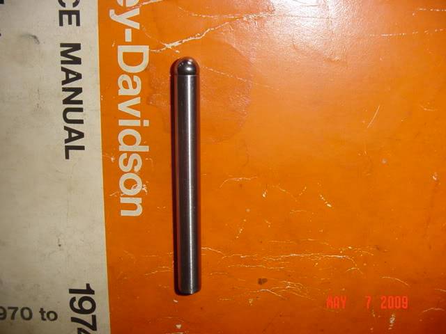
The lapping method:
The seat can be lapped with a clean bead blasted Evo pushrod end (it’s the same size as
the check ball). 12)
Basically you are reconditioning the seat where the ball sits so it creates a good seal around the ball.
The tool on the left is a homemade check ball lapping tool used to lap the seat where the check ball sits in the oil pump (57-76). 13)
It's made with a tool steel shank and a 3/8“ carbide ball tip on the end.
The pocket for the ball to sit was cut with a 3/8” ball end mill then a few drops of Loctite 404 to keep it there.
This is used as a traditional lapping tool would be. But it's not the best idea to use lapping compound in there. 14)
Particles of the very hard lapping compound will become embedded in the soft aluminum and stay there to grind up the ball in service.
Not to mention they can then come loose and circulate through your bearings.
 |
| Homemade check ball lapping tool 15) |
The burnishing method:
The tool below is a check-ball seat burnishing set. 16)
The idea is to turn the ball into the seat several times, thereby smoothing it to a very fine finish.
It works quite well with these old check valve seats, but you can and do use quite a bit of force with the cast iron for a good result.
The aluminum bodies on the Sportster pump would require a somewhat gentler application of the wrench.
But the result would be a micron finish on the seat that will hold those slippery oil molecules.
Problems with this procedure include factory machining of bore and seat rather badly out of alignment on a few pumps.
And pitted or damaged seats that no amount of force will correct.
You'd probably need a lathe, a tap set and the ability to braze or silver solder to make your own tool.
Although you might drill out and tap an un-needed pump nipple for part of the tool.
You can indicate the bolts in the chuck, face off the ends and then center drill them to provide a concentric pocket for the sphere to rest in.
Then, hold the whole mess in tension between centers as you soldered. They surely have to be straight or they aren’t much use.
 |
| Check-ball seat burnishing set 17) |
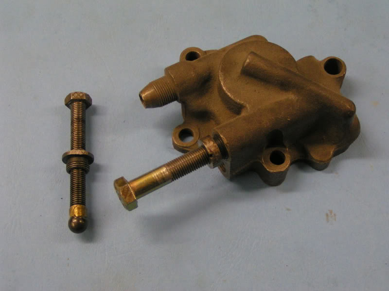
Centering the ball to the seat:
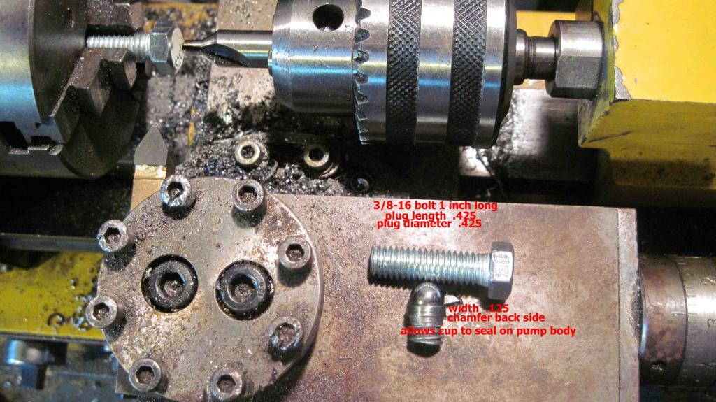
This was an attempt at keeping the ball centered, with a machined bolt. The very early oil pump's had a pin attached to the ball.
The information below is an extension of this video by bustert Youtube video on the check ball and wet sumping 18)
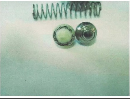
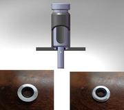
The spring and really does not home in on the ball, putting side loading on it and therefore not putting full force of the spring directly on top of the seat.
The second pic below is the homemade cup to fit into the hole.
The third pic below is of the cup installed in the body. It appears that the cup sticks up fairly high but that is not the case.
The extension is 1/32“ to 1/16” above the opening.

Cutting a spring seat in the check ball:
A spring cut was machined into the ball so that the spring is captured and can not wobble all around the ball.
Before, the spring was at an angle but now directly on top of the seat.
Since the steel ball is hardened, it must be ground in but an exotic point can cut the seat.
Imagining a Teflon ball to perform better, a spring seat was cut into it.
Since the ball is basically captured, the seat sides should conform to each other in short order.
Spring pressure:
The stock 1974 sportster spring has a collapse rate of 2.5 pounds. The difference between the cup hole of .220“ and the original pump hole of .312” is .092“. 27)
Now that sounds like a lot.
But run the sizes at a given psi through an orifice flow calculator and you will see there isn’t that much difference, especially at lower pressures.
Pascal theorem states that in a close system, the exertion of force applied is equal through as the fluid is not compressible.
Now this theorem can be modified to increase or decrease hydraulic force.
It is all in the square area of the two pistons. The smaller area must move more than the larger area but the force is multiplied and the reverse would be true.
Remember, the sportster pump system is not a closed circuit; the only thing the pump sees is the pressure or the spring and the restriction of the system.
The oil pressure gauge is reading system restriction.
Now we are going to forget totally about ball seat pressure, as it has nothing to do with oil pressure.
The spring applies its pressure to a narrow seat band and the pressure on the seat due to it's small surface is greater than the 2.5 psi spring.
It must be noted that the pump will not push the ball to total collapse of the spring; the cracking pressure is much lower than the 2.5 psi.
In calculation of the area of the stock vs. the installed cup, the ratios are .8 and .58 respectively.
This equates that for total collapse of the spring, for stock, the pump pressure would be around 3 psi.
The total collapse for the installed cup would be around 5 psi. This 2 psi is well within the range of the pump.
If you blank off the pump and run it, the pressure will be way above the restriction of the engine 7 to 14 psi.
Even at idle, when the pressure would be around 3 psi, the ball movement toward the seat would increase the output of the pump.
Now if you have a crappy high clearance pump with a lot of slip, the pump needs replacing.
Breather Gear Shaft Mod
The leaking check ball is the most popular theory out there. 28)
However, the check ball can be perfectly good and the bike will still wet sump.
The oil can go right up the pump shaft directly into the cam box.
There is definitely a clearance around this shaft for the leak, but the clearance around the check ball is reduced/eliminated by the spring pushing the ball shut.
There is a small oil seal between the feed and scavenge gears around the shaft.
The seal will harden over time and the elasticity will be moot so it is a replacement item.
However, even with a freshly overhauled pump there can be a sumping issue.
There was no seal until mid 1958.
Seepage into the return side from feed side will try to get into the cam case.
It usually don't though. It ends up in crankcase instead. Same with any oil that can back feed down return line.
Bikes that, when on the side stand, have the oil level in tank over top of the return or vent opening may siphon.
This is why the XLH oil level is high in tank but the XLCH horseshoe tank is way lower. Having the vent siphon is worse than return.
In the mid 60's, HD modded the XLH oil filter canister to break siphon on a rare circumstance that would really load the engine.
The oil passes in the gap of the top of the keyed feed gear to reach the breather valve shaft.
As the level in pump rises over time, oil passes between the shaft and it's bore in the cast iron top housing where it ends up around OD of the breather gear.
It runs up the gear/housing clearance until it sees the port for the crankcase scavenge air and starts filling the crankcase.
As an additional item when oil gets to the outside of iron housing tower thru the port, it can travel to front side of tower where it seeps into the cam case catch basin.
Although this isn't a big issue.
Oil in cam case is way more apt to puke out the breather than the crankcase oil. Guys with kickers will realize there are 2 different puke scenes.
- When you push the kicker thru for the first time you hear that the bike is gonna puke but it doesn't actually puke until 2 or 3 kicks.
This is crankcase oil. - As soon as you touch the kicker, oil is blowing out of tube. The cam case is full of oil.
This usually is a vent line back feeding tank oil to cam chest.
If you have this (2) scene cronic, it means you may be allowing the oil level to be so high its over the top of the vent in tank.
Or, the vent pipe in the tank is broken. Either way, that's not the only problem.
In order for oil to drain from the tank thru the vent line to cam case, air has to be able to get into tank.
Finding and fixing the air leak will make a world of difference.
Another point to ponder.
It was once common for the K model to never puked but just leak.
The few guys who still run the 62< spring loaded generator gear face seal will also have similar experience.
These bikes are just as apt to puke when kicking as any others. Once running, they are pretty self contained unlike the 63> washer type.
If you got an oil cooler or filter that's on the return line AND THESE ARE MOUNTED HIGH ON THE BIKE, THEY WILL GRAVITY BACKFEED into return side.
This can happen when the return port on the tank is above the tank oil level.
The replacement air flows into the open puke tube thru the cam chest into vent line and back to the tank where it gets sucked into the return line as cooler drains into motor.
For you efficiency driven guys. Why aren't you sticking a piece of 3/8” hose to the end of the puke tube and putting the other end back in oil tank?
And for those who can't or won't run the restrictive 62< setup. You may want to consider a virtual 62< setup. It works like this:
- Remove the tank cap.
- Fire the bike up.
- As fast as possible, plug the end of the puke tube with your index finger.
- Hold for 15 seconds.
If the pressure gets to high, pump more rpms to the motor and the pressure will lower. - Release your finger.
- Put the cap back on.
- Ride
High tech but xl's seem to tolerate it.
If you have a 70< that pukes after sitting and it still has a transfer valve or siphon tube 54<, try this the next time you park it.
Crack or remove the primary filler plug (XLH) and remove the upper primary inspection cover screw (tin cover bikes).
Put the plug back on just before your next ride and see if the puke goes away or gets better.
You may be observing something that was designed on purpose from the factory.
Below are some ideas for fixing a leaky shaft seal.
By bustert
Normally, you'd use precision equipment for this. However, below shows how you can do the job with common home tools.
The cost of this project would be $4.00 U.S. for the bushing and whatever you can find a milling bit for.
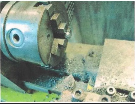
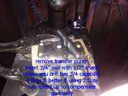
Done with a 1/2“ shank because most will not have a 3/4” capacity chuck.
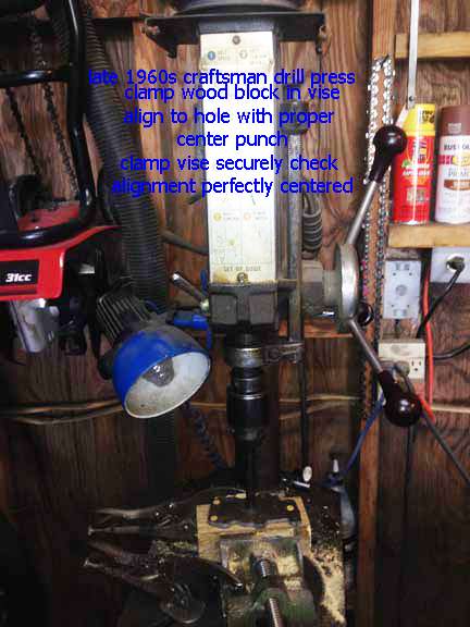
The late 1960s Craftsman in the jpeg below has 5/8“ capacity and is the original. The quill is still tight so accuracy is close enough.
As with any boring, keep the work as close as you can.
The 4 fluke would be better but if you speed up the drill, then it compensates, just go slow with lube so no chatter is induced.
The process:
- Square a block of wood thick enough to fit the vise and allow the extension to fit without bottoming out.
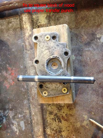
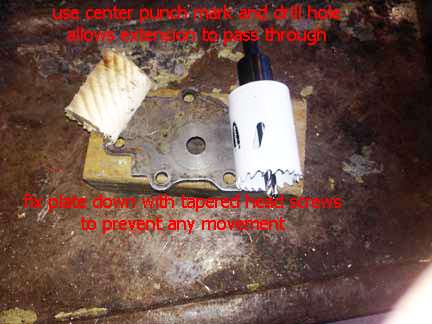
- Attach the upper plate to the wood block with tapered head screws to prevent movement.
- Use a transfer punch of proper size and mark the wood block, remove upper plate.
- Bore out proper size plug and insert the upper plate extension into the hole and fix with tapered head screws to prevent movement.
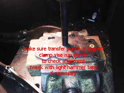
- Fix block of wood to vise and use proper size transfer punch to align to the quill.
Clamp vise securely and make sure punch is center and moves freely. If needed, tweaks can be made by sight taps to the vise. - Now you can slowly mill the hole. Take your time as the plate is cast steel.
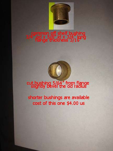
Now you have the hole. The bushing needs to be sized but you can find shorter lengths.
Now from the bottom of the flange, measure up 5/64” and cut the bushing and round off the radius to ease installation, just the very edge.
Do not get into the seating area.
Once this is done, place the upper plate on a block of wood with a 3/4“ hole drilled in it to support the plate when installing the bushing.
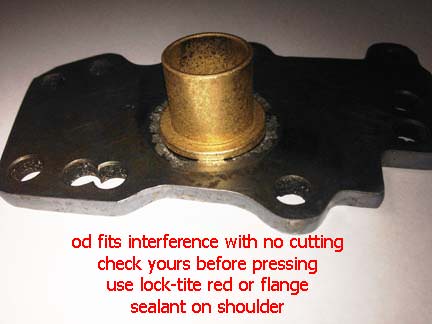
Make sure it is squeaky clean, add red Loctite or flange/bushing sealant to the underside of flange, install into the hole and let it set up.
As an option, you can slightly run a taper drift into the bottom side of the bushing and slightly taper out the hole to add more interference fit IF you want, the sealant should be enough to cement the bushing. now dress off the bushing flat to the plate and you are good to go.
Now all you do is insert the seal into the bottom of the bushing cup side down till flush.
These plates with extension can be made from regular steel and tubing.
By Ferrous Head
The pump already has an oil seal in the body of the pump.
This seal stops oil from leaking past the shaft on the scavenge side and into the feed side gears.
What HD didn't do was use an oil seal above the feed gears to stop oil leaking past the shaft into the pump tower.
So the shaft itself just runs against the cast iron pump tower until it wears enough clearance for itself to not interfere with the oils passage.
Once that happens the pump will leak.
With the bike leaned on it's kick stand, the oil leaks into the sump and then overflows into the primary case via the oil transfer valve in the left case half.
This really is a design flaw and should have never been allowed to persist.
This solution is to install a seal in the pump tower.
The biggest problem here is the area that should hold the seal is only about 3mm thick.
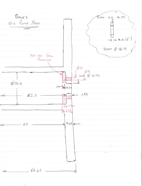
And the answer to that problem is to machine up a “top hat” to be pressed into the pump tower to hold the seal.
The seal used is the same seal used in the pump body (26227-58), about $4 worth.
The machining was farmed out to a local shop. It took them 1/2 hour to make two top hats, machine the towers and press in the top hats.
They also made two tools for the installation. Both tools are very simple for anyone with a lathe to make.
The first is a backing tool that stops the pump tower face from distorting (bending inwards) when the top hat is pressed into place.
The second is a seal installer. However, it can be dome without the seal installer.
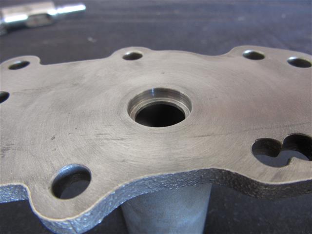
After the top hat is pressed into place, the pump tower face is faced off.
So, $55 for the machine work and $8 for two seals.
Below is a sketch of the top hat. The measurements are metric but can asily be converted to inches.
The machined tower with the hat already pressed in is to the right.
It should be clear to your machinist what is required from this. The actual line between the pump itself and the top hat is hard to see but it is there.
Click on a pic to enlarge.
Here are pics of the tools (made from mild steel) that were made for installation.
They are coated them with Soft Seal to keep them from rusting while waiting to be used.
As you can see, they are quite simple and can be made in a few minutes by a competent machinist.
One is used as “backing” or the pump tower when your installing the top hat.
The pump cover is only about 3mm thick and you could bend it when your installing the top hat.
Also below is the tool to install the oil seal. Not really necessary but it makes the whole job faster and easier to do.
By needspeed
When the pump is together there is a 3/16” space between the bottom of the breather sleeve and the top cover.
Enough room for a 1/8“ thick insert that holds the seal and is tight to the I.D. of the cover tube.
It has a relief cut to clear any radius or chamfer that sometimes is left at the bottom of the hole.
It also makes a space for any excess sealer that could be used. There are no mods to any part of the pump.
This was made from aluminum on a lathe.
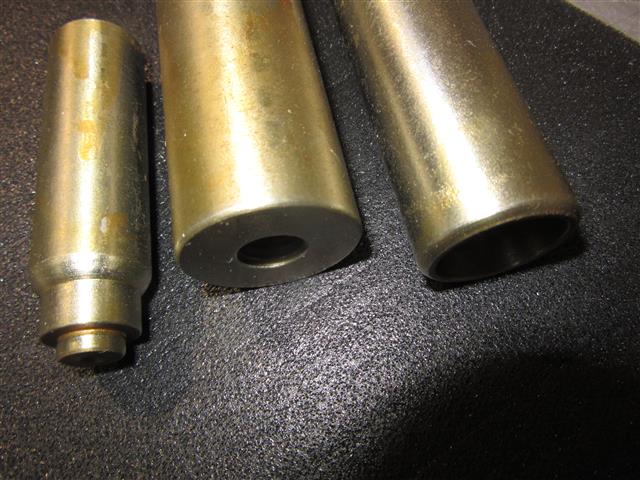
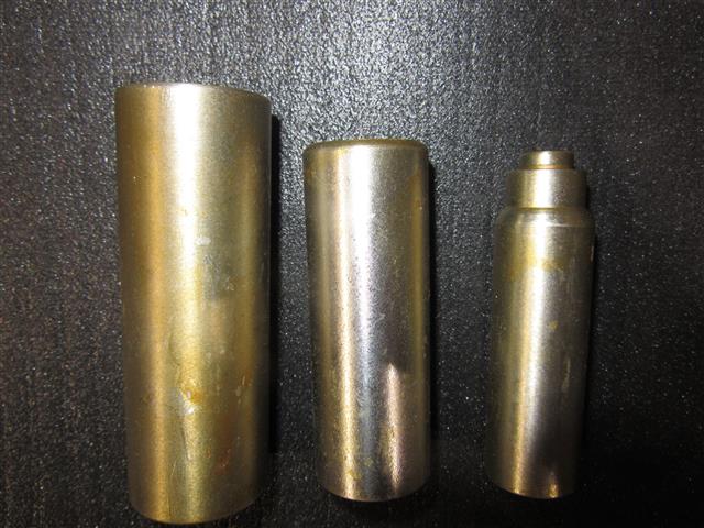
Pump Body Damage
1952-1976 oil pumps cannot be removed/installed without either removing the engine from the frame or at least leaning the engine over in frame.
This makes questionable imperfections more to a higher degree of scrutiny than 77-up gerotor pumps that don't require engine uprooting.
Below is a compilation of just a few oil pumps with various gear well damage.

Roll Pin Damage/Removal
Generally you have 3 lines of action depending on what you're up against. 42)
- Squeeze exposed od of pin so it gets smaller and releases the press fit in the hole.
- Make a “fishhook” tool with an eccentric lip that you can slide thru the center of the pin.
Then rotate 180° once the ecentric lip passes the blind end of the pin.
Put shank of tool in a vice and tap on part. PIA, but do-able in garage. Doesn't molest part. - The most extreme but the most effecient and most often the only option.
Get a drill bit that fits thru the center hole of the busted pin.
Drill clear thru parent part with this bit. Flip part over to get the far end of this thru the hole.
Sometimes you can get a drift in this new small hole and catch pin. Tap the pin out.
If you can't catch the pin with the drift, from far side enlarge small hole with bit bigger than 1st but smaller than actuall pin hole od.
Fit drift thru this hole and tap pin out. Original hole area remains uneffected. New pin will fit normal.
Idler Shaft Removal
If the idler shaft is damaged, you can remove it by applying heat (150°F) to the pump body and the shaft should fall out.
Heat the pump body to (150°F) to install idler gear shaft. Shaft may not protrude above either oil pump body face. 43)