Table of Contents

REF: Body Parts - Sub-30H
Rear Foot Controls
Forward Controls to Rearset Conversion
Article by Gone of the XLFORUM 1)
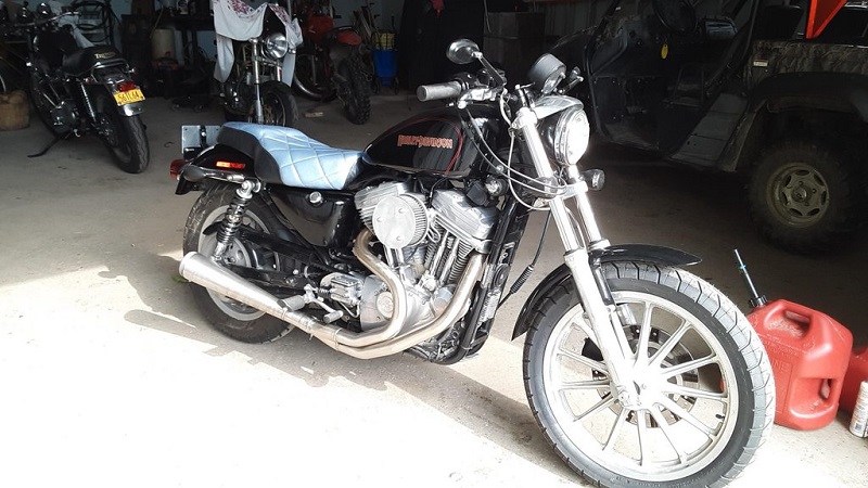
These are forward Controls to rearsets on a 2007 1200 Custom while keeping the parts as OEM as possible.
This conversion doesn't damage the forward controls, they can be reinstalled when required.
Extra materials: app $40.00
Total time to modify: app 8 hours.
The ground clearance is the same after the mod.
The lean angle still sucks on the pipe side as the pipes ground way before the pegs.
On the gear side, there is way more lean available.
Converting the pillion foot peg mounts:
The pillion peg mounting lugs were cut off which left a flat, round surface.
Two round steel spacers (1-3/8” Dia, 5/8” thick with a 7/8” hole through the center) were made on a lathe.
Weld one spacer to the outside of the brake side mount and the other to the inside of the gear side mount.
(this gets the foot peg spacing correct, equal distance on each side)
Make sure to center the spacers correctly.
Once welded, drill out the remainder of the mount with a 7/8“ drill bit.
The shift lever from a set of mid controls were used on the gearbox output shaft to get the shift rod high enough to clear the primary case.
However you could use the selector lever that comes standard with the Forward control setup.
Make an 'L' shaped bracket (about 120°) to attach the pushrod (5/16” alloy was used here and shaped round to match the gear lever).
It will have a 7/8” hole at the center of the 'L' to pass the foot peg trough.
(basically you make it the same shape as the inner profile of the gear lever.
Bolt the L bracket to the forward control lever using the hole that was used to mount the forward control pushrod.
The new lever is located by the foot peg shaft and held in place by the old pushrod bolt.
Then all that is left to do is make a new pushrod.
5/16” stainless steel rod ends and a 5/16” stainless steel rod were used here.
These are obtainable from most steel/engineering suppliers.
With the mounting bracket made, next assemble the brake lever and foot peg.
You will have to modify the brake lever mechanism.
A stainless steel plate (5-1/2” long, 7/8” wide and 1/16” thick) was used here.
Drill a 5/16” hole at one end and a 3/16” hole at the other.
And another 5/16” hole 2” up the plate from the 3/16 end (this hole is for the push rod mounting).
This plate mounts between the center locating bolt of the drive belt cover and the rear brake master cylinder pushrod mount.
You will need to buy two new bolts along with some lock nuts and washers;
One bolt to replace the locating bolt of the drive belt cover (it will need to be 1/2“ longer)
And one bolt for the rear brake master cylinder pushrod mount (1-1/2” longer).
The brake lever plate needs to float.
It must pivot on the center locating bolt of the drive belt cover and the rear brake master cylinder pushrod bolt (must be free to move).
That is why you need to use lock nuts and washers to lock the bolts in place and allow some endplay for the brake lever plate.
Once that’s done all you need to do is make the brake pushrod using the same type of rod ends and rod as used for the gear change.
And finally, 1-1/2” was cut off the pillion pegs to use those instead of the standard forward pegs.
This reduced the width of the bike added to the look.
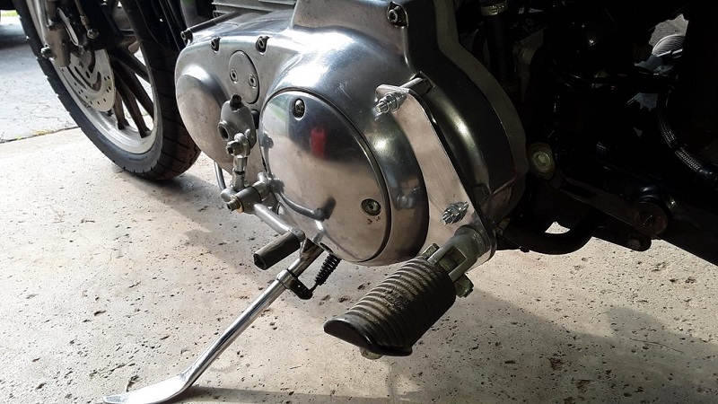
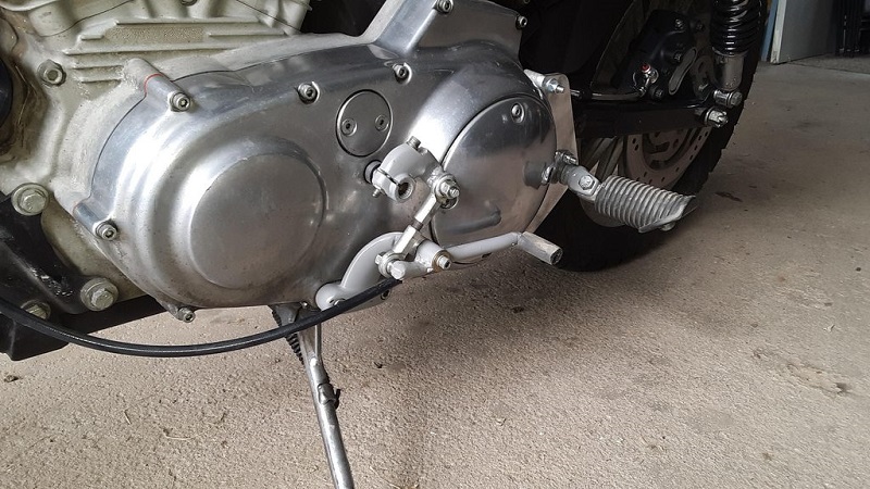
| Gear side controls. 2) | |
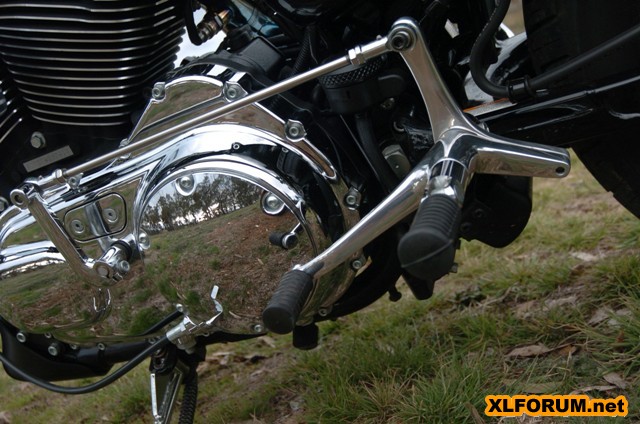 | 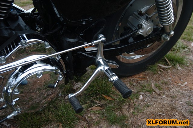 |
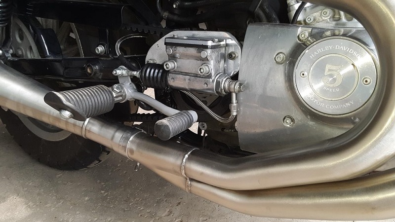
| Brake side Controls. 3) | ||
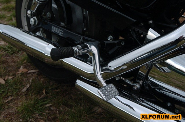 | 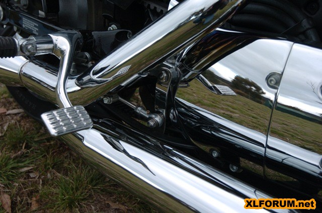 | 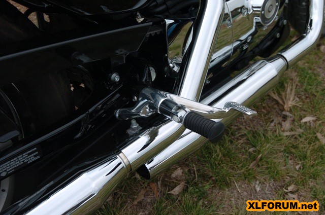 |