Table of Contents
This is an old revision of the document!

REF: Electrical System
Ironhead - Schematic Drawings (created with reference to the OEM manual)
1959-1985 Sportster Main Wiring Diagrams
The drawings below have been created using the factory schematic drawings from the FSMs as reference.
They are available here but are not intended to replace the factory drawings.
Some parts symbols are generic, may not represent the actual period parts and have been spread out for clarity from the originals.
However, the parts are labeled.
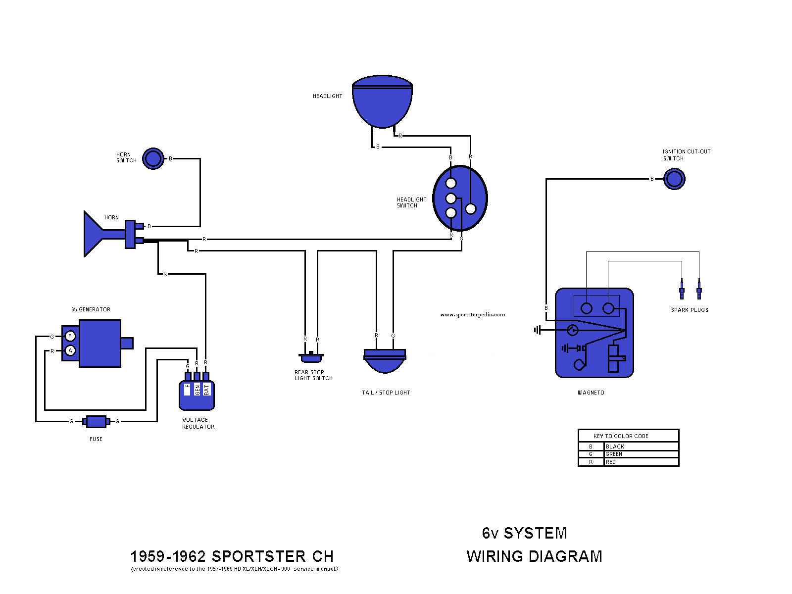
1959-1962 Sportster CH
Click on the drawing to enlarge:
1959-1964 Sportster H
Click on the drawing to enlarge:

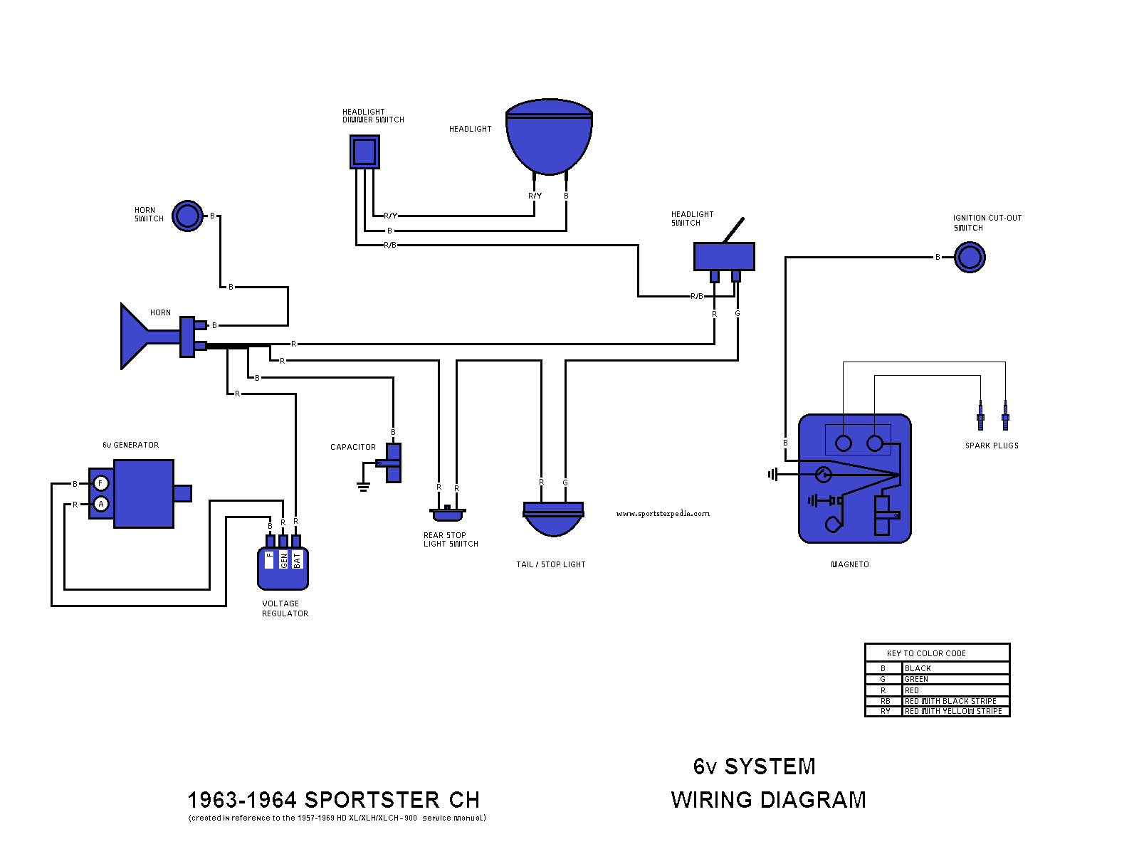
1963-1964 Sportster CH
Click on the drawing to enlarge:
1965 Sportster CH
Click on the drawing to enlarge:

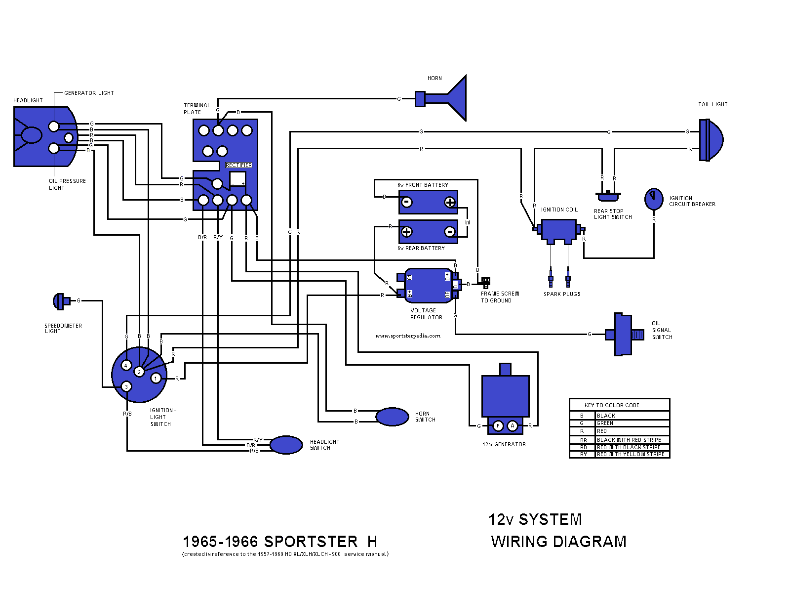
1965-1966 Sportster H
Click on the drawing to enlarge:
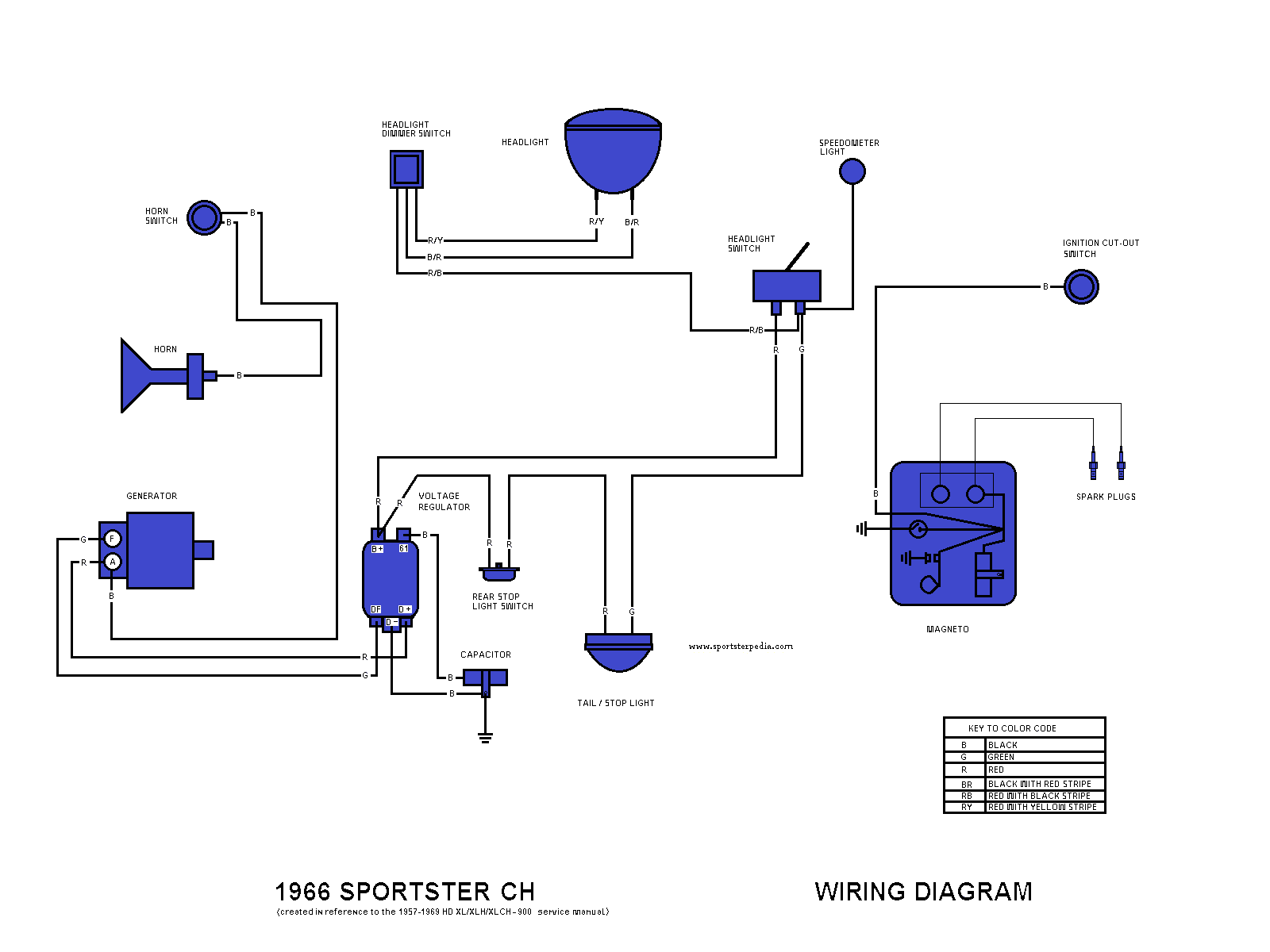
1966 Sportster CH
Click on the drawing to enlarge:
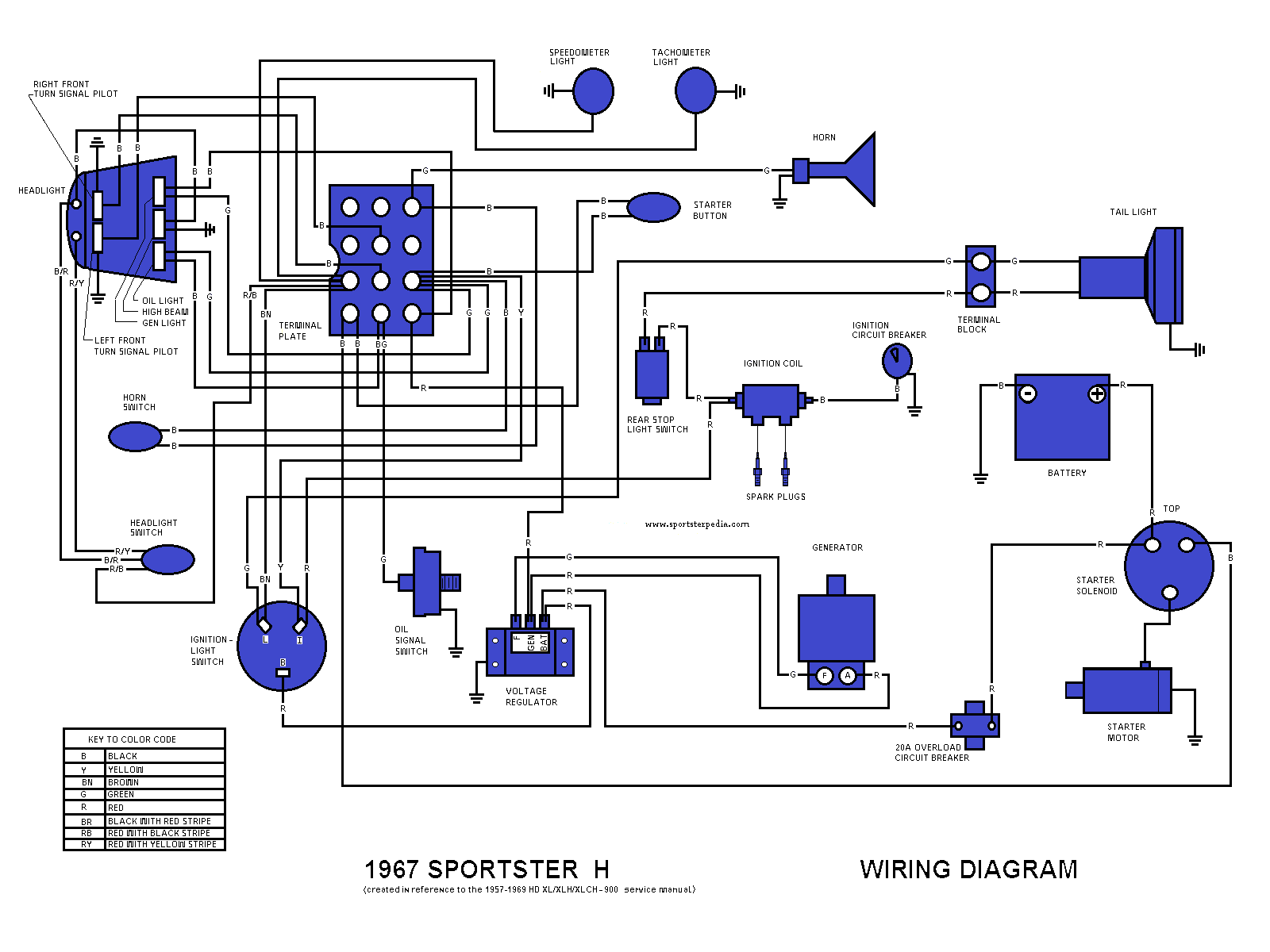
1967 Sportster H
Click on the drawing to enlarge:
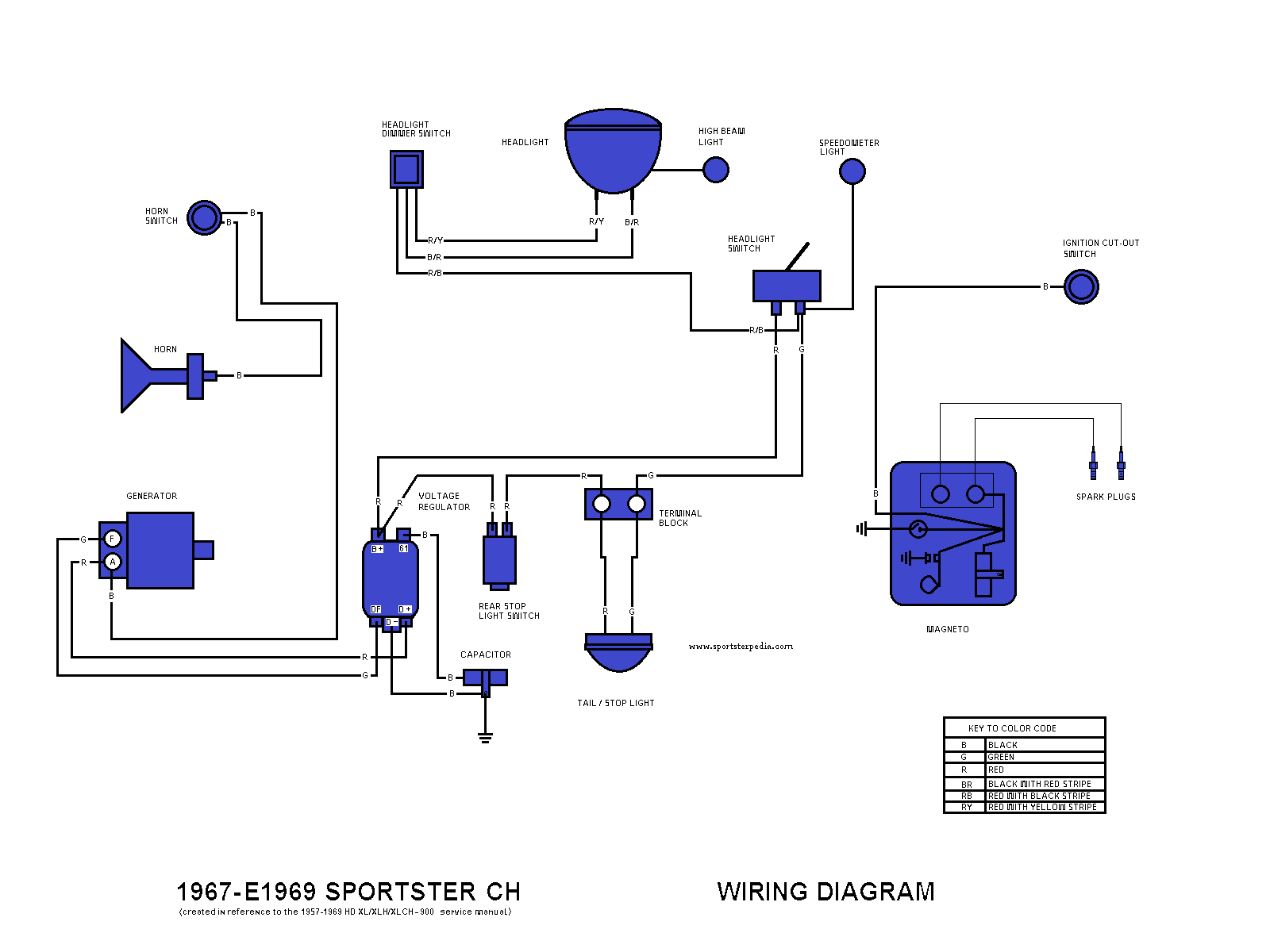
1967-E1969 Sportster CH
Click on the drawing to enlarge:
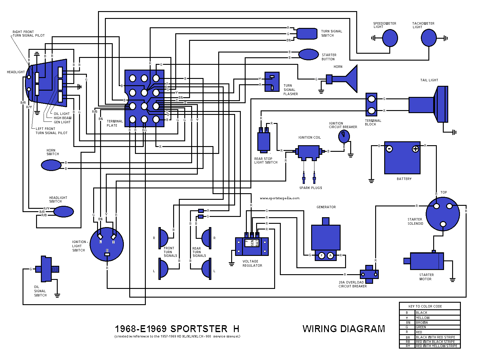
1968-E1969 Sportster H
Click on the drawing to enlarge:
L1969 Sportster H
Click on the drawing to enlarge:

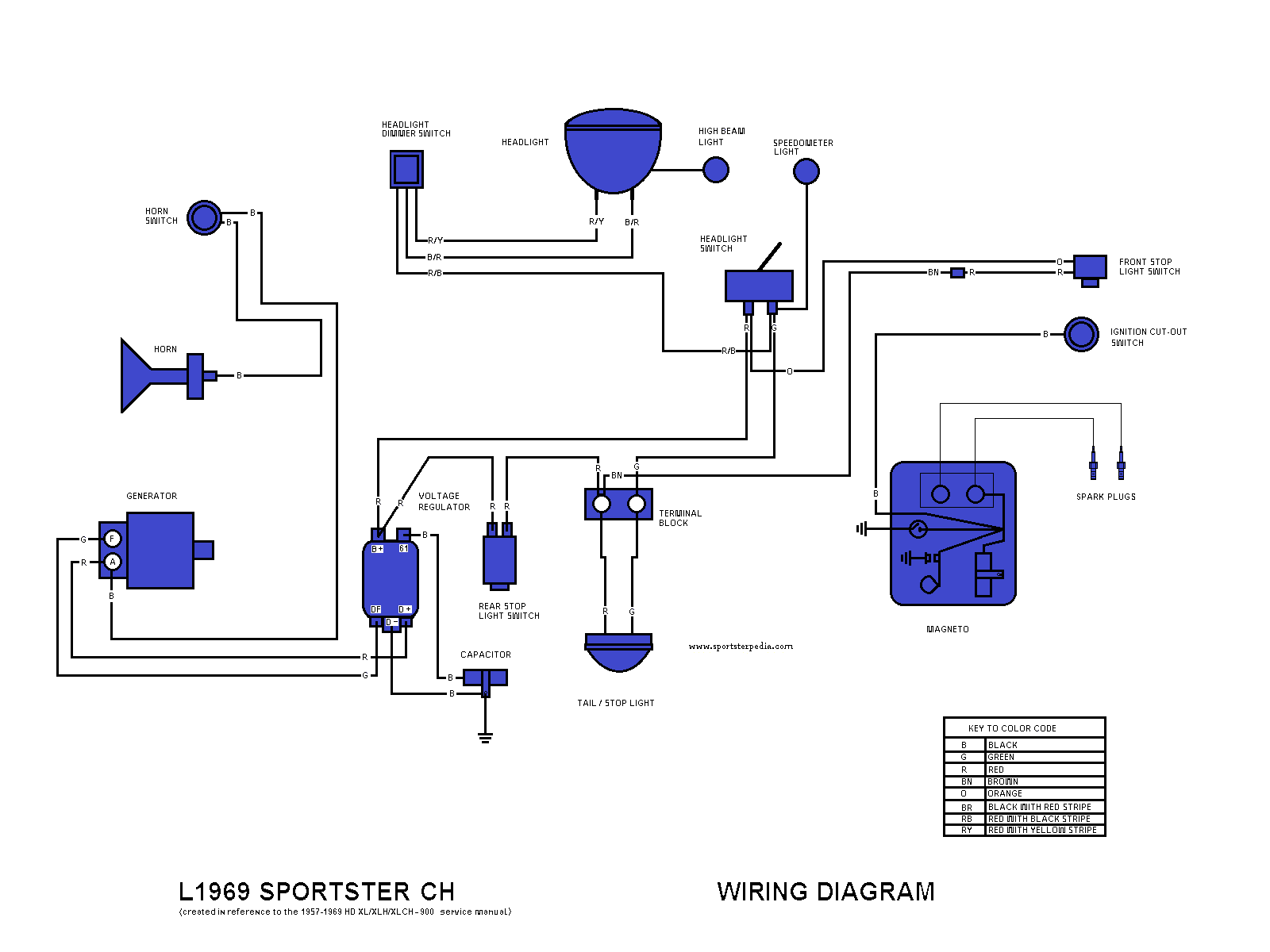
L1969 Sportster CH
Click on the drawing to enlarge:
1970-1971 Sportster XLH
Click on the drawing to enlarge:

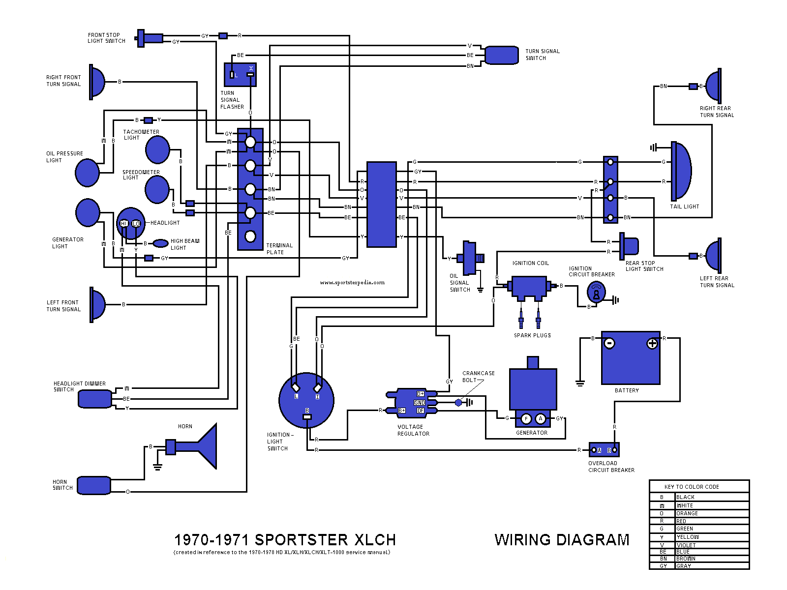
1970-1971 Sportster XLCH
Click on the drawing to enlarge:
1972 Sportster XLH - Standard Seat
Click on the drawing to enlarge:

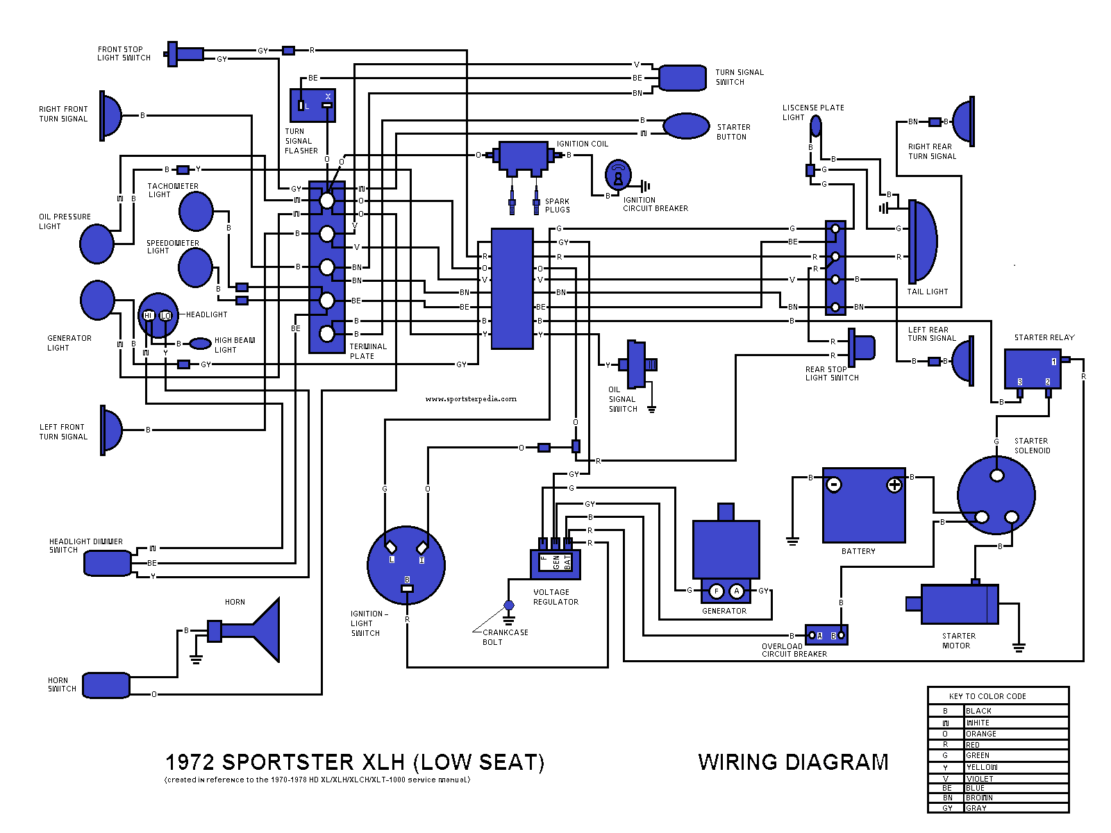
1972 Sportster XLH - Low Seat
Click on the drawing to enlarge:
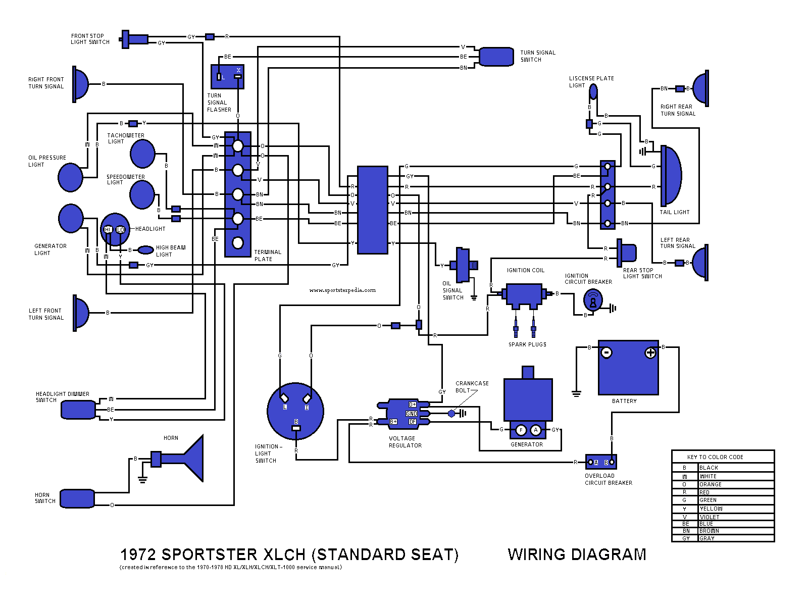
1972 Sportster XLCH - Standard Seat
Click on the drawing to enlarge:
1972 Sportster XLCH - Low Seat
Click on the drawing to enlarge:

1973-1974 Sportster XL
Click on the drawing to enlarge:

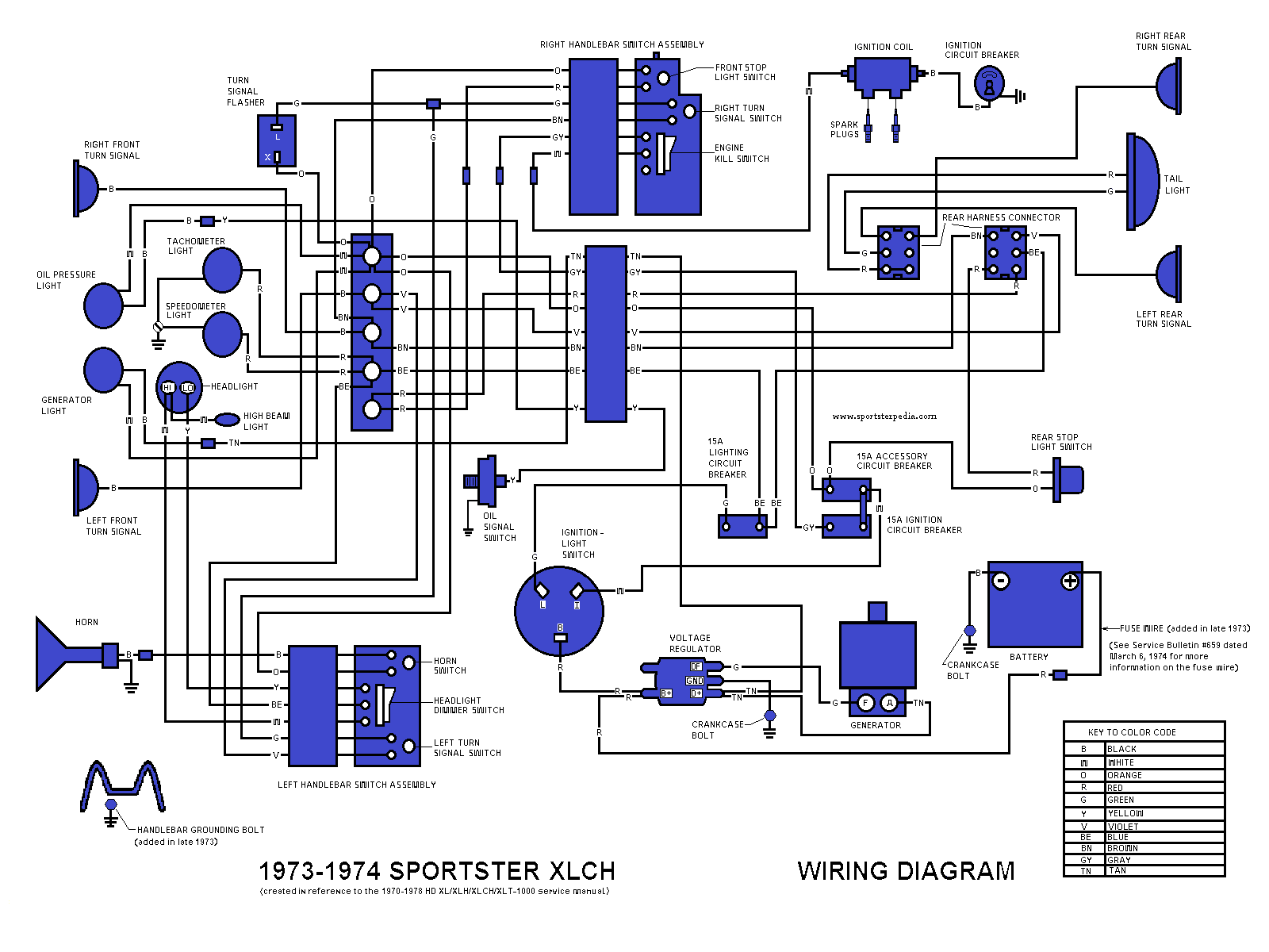
1973-1974 Sportster XLCH
Click on the drawing to enlarge:
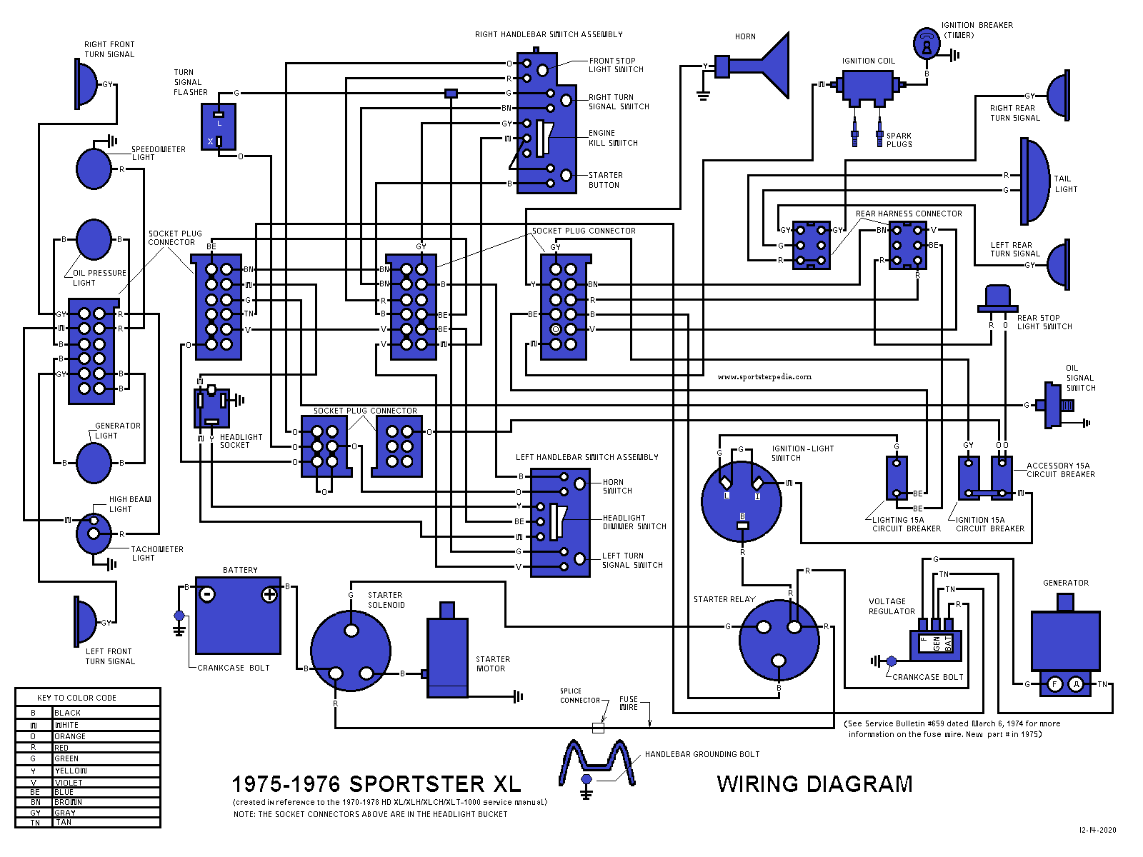
1975-1976 Sportster XL
Click on the drawing to enlarge:
1975-1976 Sportster XLCH
Click on the drawing to enlarge:

1977 Sportster XL
Click on the drawing to enlarge:

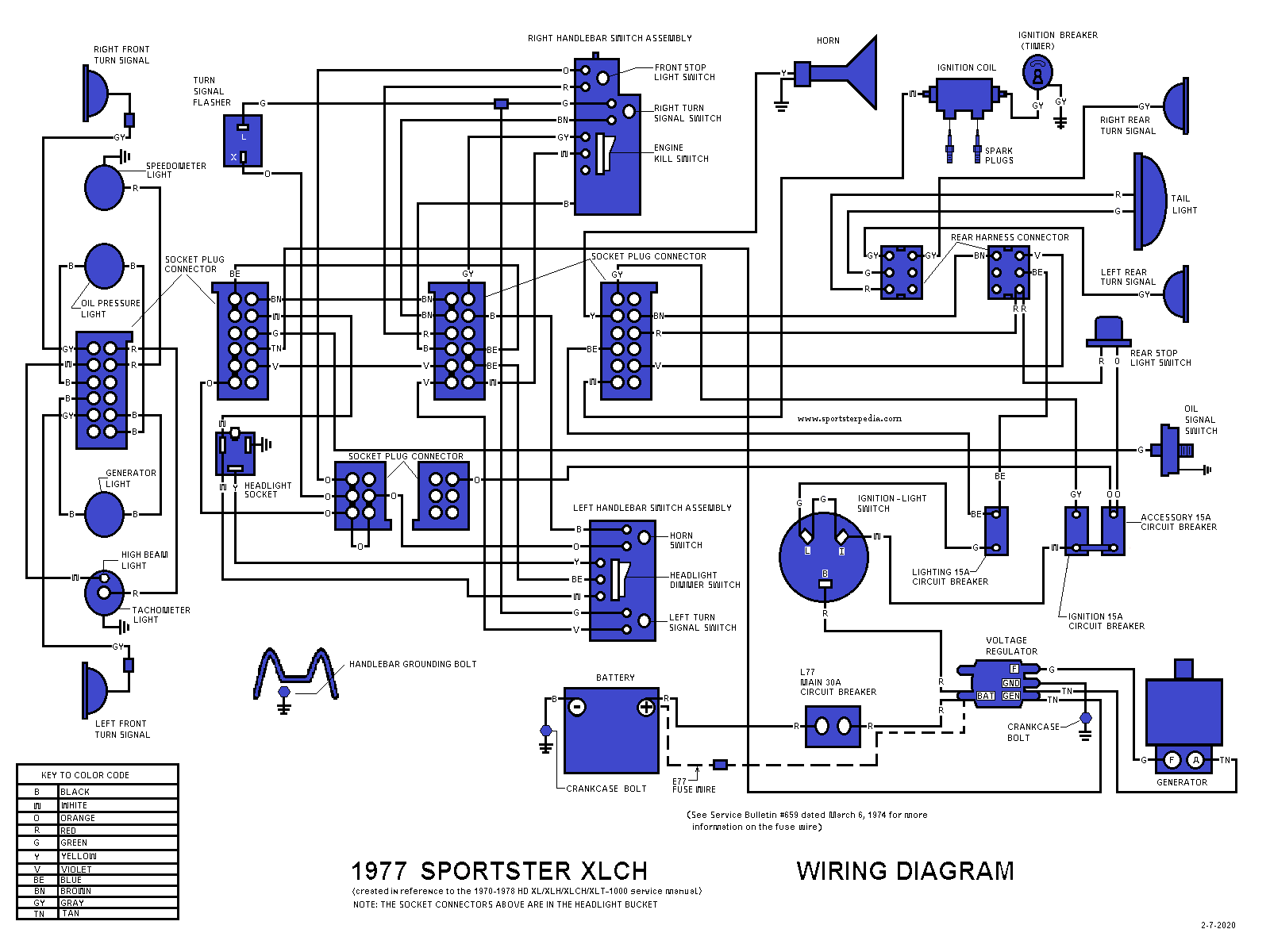
1977 Sportster XLCH
Click on the drawing to enlarge:
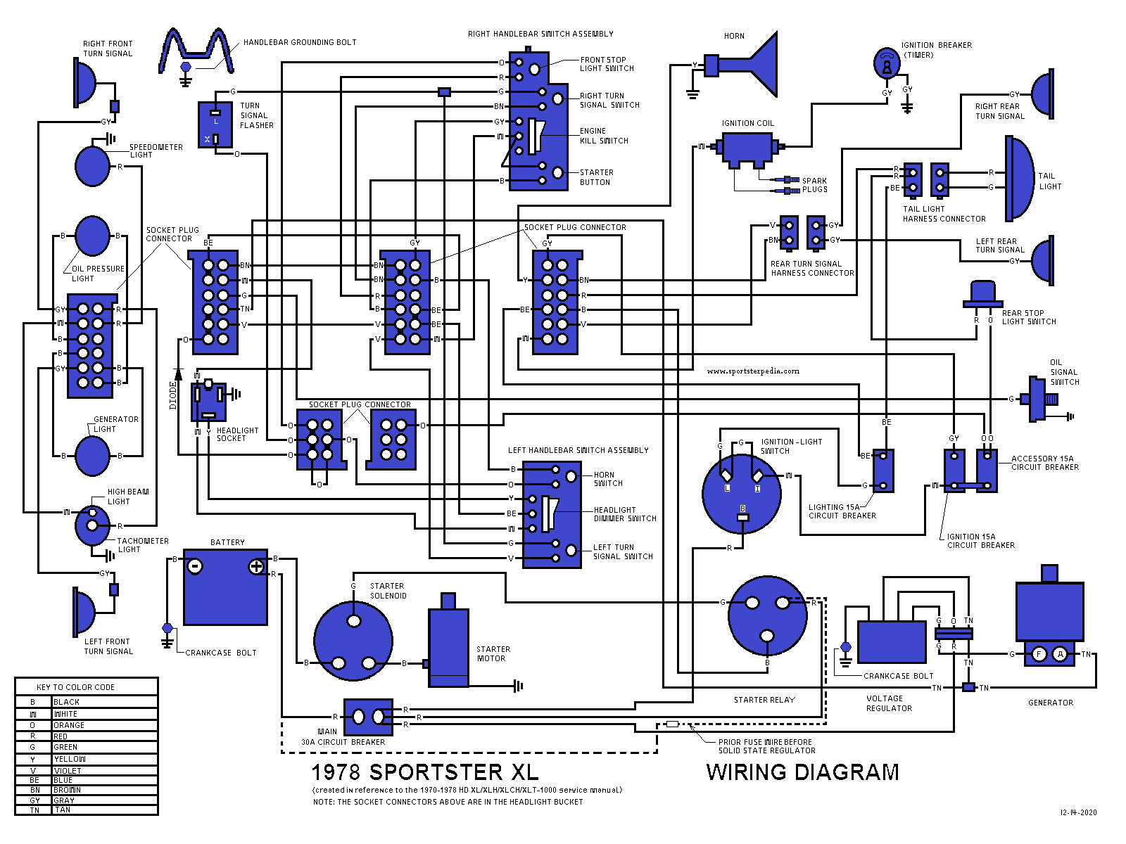
1978 Sportster XL
Click on the drawing to enlarge:
1978 Sportster XLCH
Click on the drawing to enlarge:

1979 Sportster XLH/XLS
Click on the drawing to enlarge:

1979 Sportster XLCH
Click on the drawing to enlarge:

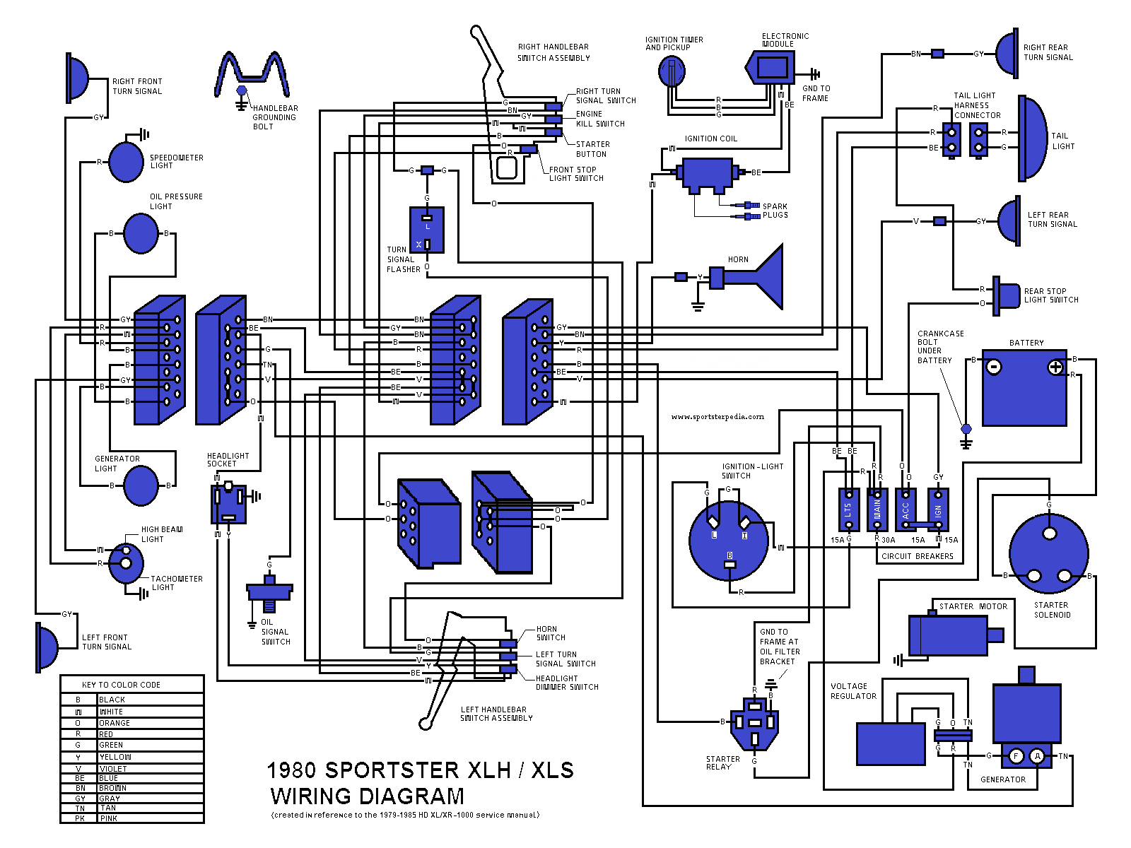
1980 Sportster XLH/XLS
Click on the drawing to enlarge:
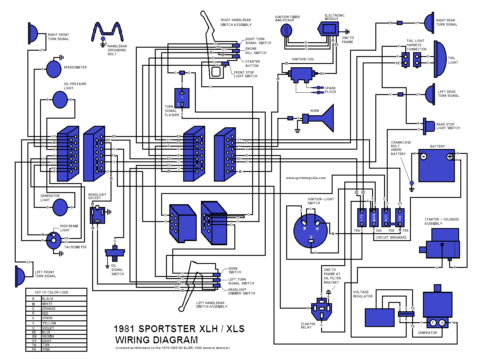
1981 Sportster XLH/XLS
Click on the drawing to enlarge:
1982 Sportster XLH/XLS
Click on the drawing to enlarge:

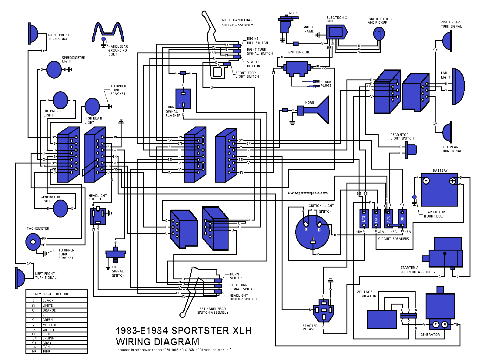
1983-E1984 Sportster XLH
Click on the drawing to enlarge:
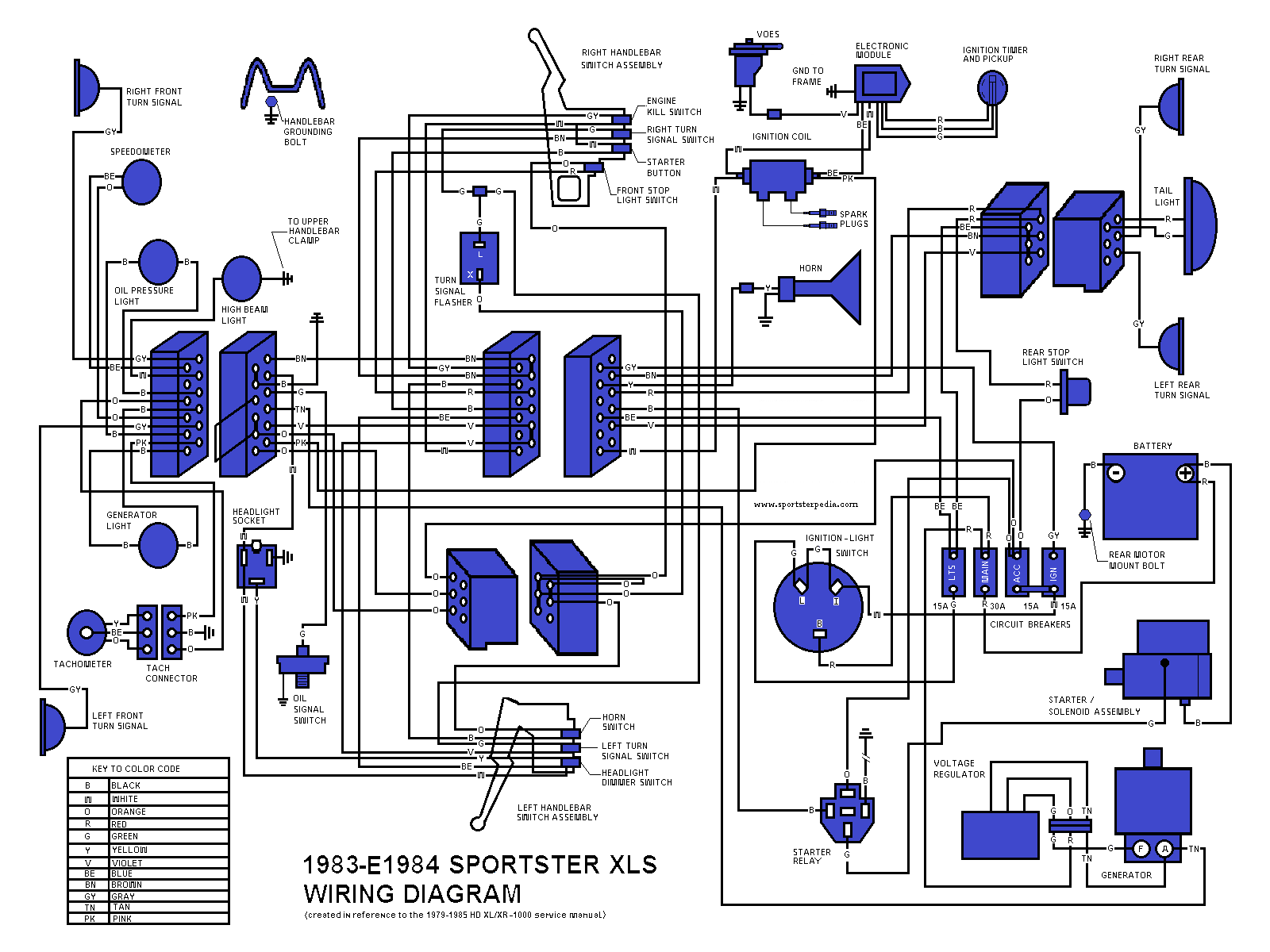
1983-E1984 Sportster XLS
Click on the drawing to enlarge:
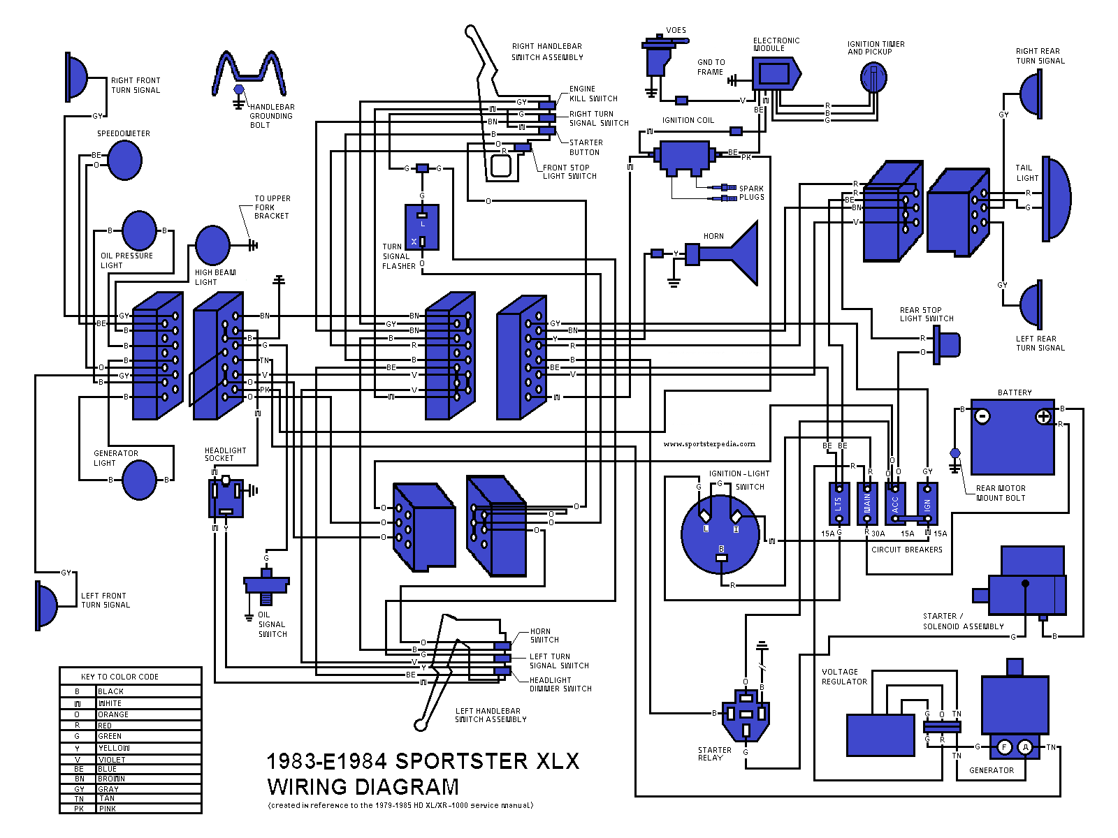
1983-E1984 Sportster XLX
Click on the drawing to enlarge:
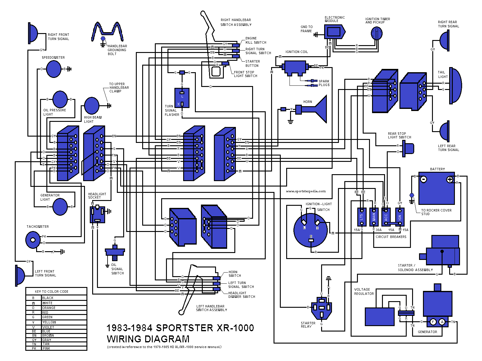
1983-1984 Sportster XR-1000
Click on the drawing to enlarge:
Ironhead - Simplified Wiring Schematics
This wiring diagram is a minimal config - No Starter - No Turn Signals - No Front Brake Switch - No Kill Switch.
The ignition module is an Ultima version and fits in the nosecone where previously only the cam sensor plate was mounted. In this diagram the Ultima Single-Fire Configuration is used, feeding separate trigger signals to the dual coils to fire the front & rear spark plugs separately (the Ultima BLUE wire fires the front coil & the Ultima PINK wire fires the rear coil).
If you choose to use a dual-fire configuration of the Ultima ignition, it will also work when you pair it to the appropriate dual-fire coil. In that case, you will only use the Ultima PINK wire to fire the selected dual-fire coil. (The Ultima BLUE wire will not be used at all with a dual-fire version.)
Using the VOES connection with either configuration (which helps with idle & cruising spark timing by providing more advance) is recommended by connecting the Ultima VIOLET wire to the VOES unit.
Implementing a tachometer is optional. If used, the Ultima GREEN wire will connect to the tachometer signal input wire. The tach will also need a ground connection on the bike and key-operated power for the tach light.
There are only six wire colors to minimize wire purchase: Black - White - Red - Blue - Yellow - Green. There are enough colors so that no connecting point should have the same color twice in order to make it easier to know which device is connected to/from another device.
This circuit uses the Frame/Engine for ground conduction. Be sure you have good ground points at the needed locations or run a separate black wire to those locations to assure a good ground.
Beware that the brake light shares the same fuse as the ignition circuit - So, if you have a short to ground in the brake circuit it will blow the fuse & kill the ignition. You could add a separate fuse for the brake light to avoid that potential problem.
The diagram shows an optional Gen Light, implemented with a diode and an incandescent bulb.
To implement the VOES, add it with a vacuum hose to the carb - then wire the single VOES wire into the Violet Wire of the Ultima ignition module.
To implement a tachometer, use a normal HD dual-fire tach and wire the input signal to the Green Wire of the Ultima module.

Some Other Simplfied Wiring Diagrams to represent basic wiring:
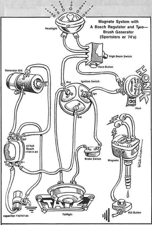
| Wiring for Magneto Fired Sportsters 35) |

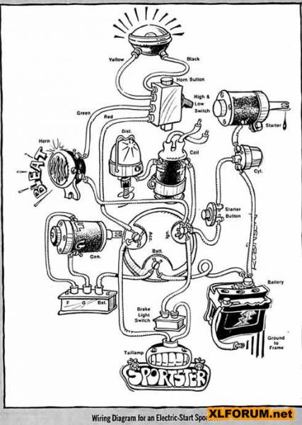
| Wiring for an Electric Start Sportster 36) |
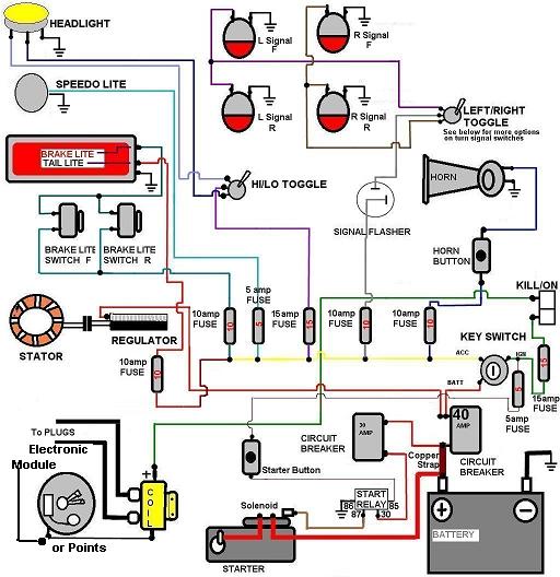
| Generic HD Wiring Diagram 37) |
| Ironhead CAD Wiring Diagram ('77) 38) |
