Table of Contents

REF: Engine Mechanicals - Sub-04L
Head Vents vs Cam Chest Vent
CC pressure (while venting thru the heads) was tested with a slack tube as in above.
Results of the testing showed that the test bike did perform as designed using breathers in the rocker boxes.
Sustained RPM on a street bike can be up in the 4000-5000 RPM range at highway speeds.
The test bike showed a positive charge forming in the crankcase around 5000 RPM.
This positive charge is responsible, in part, for oil puking out the vent(s) if the pressure gets too high.
So the farther past 5000 RPM, the more positive pressure is created.
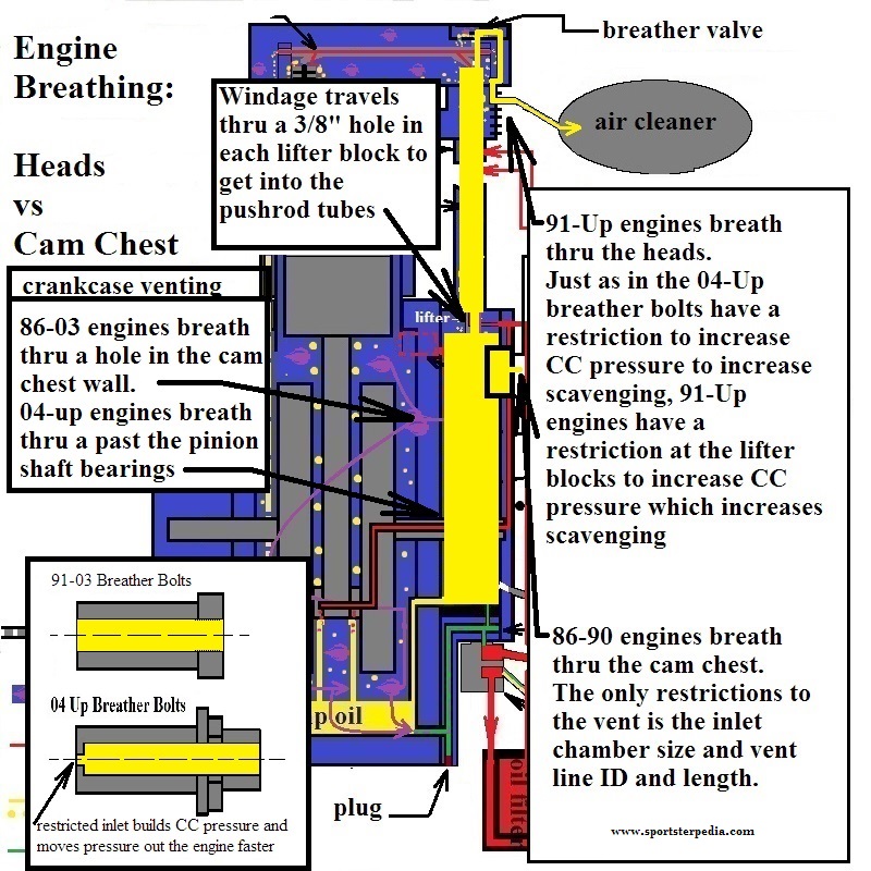
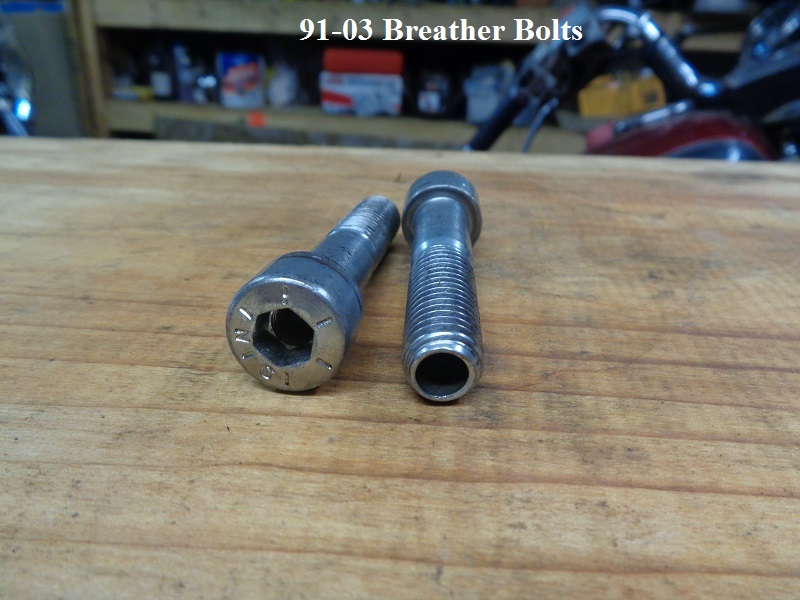
91-up Breather Bolts
The MoCo manipulated crankcase pressure with the different size holes in the breather bolts.
The crankcase splash holes were restricted in 2000 to keep more pressure in the crankcase.
Then the holes in the wall was closed up in 2004 to accommodate the addition of piston jets to cool the pistons.
The piston squirters (feed pressure from the pump) added the same amount of oil into the crankcase at a faster rate.
But the scavenger gerotors were not redesigned larger until 2007 to remove the oil faster from the crankcase.
So on 04-06 models, they got the same scavenge return rate (as previous models without the added oil).
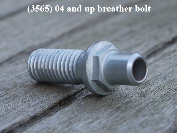
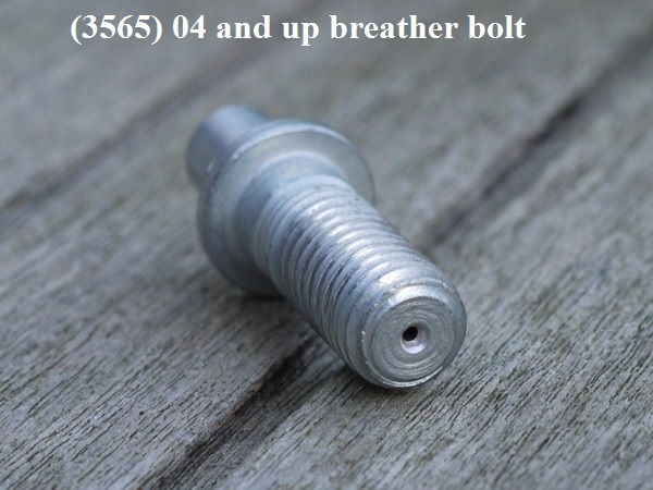
The holes in the 04 Up bolts are stepped. They are smaller on the head side as above but bigger on the A/C side.
First, that creates more of a restriction than 91-03 models. The restriction can do a couple things:
It will create more backpressure inside the engine until a stronger force is applied from inside.
That stronger force would be the air created on downstroke. In a perfect world, the downstroke won't be impeded so the force won't slow down.
The higher positive pressure assists in oil scavenging (the pressure inside builds a little more from that restriction). 2)
But it only bottles up pressure on downstroke and only to a point. That little more positive pressure is an extra push on the lower end toward the sump scavenge port.
Another result would be air moving out at a faster rate thru the smaller hole. The smaller hole creates higher pressure. Higher pressure equates to faster flow.
Head Drainage
The debated question on head breathing systems is;
When the engine is running at high speed, is there any kind of pressure being created that might slow down the drainage from the top? 6)
The oil feed to the top end is pressurized and the return is gravity fed. 7)
The drain for the top end is at least 2-3 times larger than the hole in the pushrods.
It's been said that CC pressure moving up the pushrod tubes interferes with drain oil traveling down the tubes. 8)
However, drain oil mainly goes into the head / cylinder drain holes from the rocker arms spraying the valves.
And liquid oil is much heavier than air moving up the passage.
Separated oil from mist falls back into the tubes. But that oil is also pulled down on piston upstroke and air/mist once again goes up on piston downstroke.
The higher venting from the heads also gives any oil that may be being carried along with the gas time to “drop out”.
(which returns the oil back to the cam chest vis the pushrod / lifter block drain holes via gravity)
Obviously, there is less time for oil to drop out of suspension while breathing out the cam chest instead.
The slack tube testing shows there is a predominate vacuum in a running engine until after 5000-6000 RPM.
Any output pressure in the head venting system has to travel up through separate pushrod tube passages to get out of the engine.
Any separated oil gravity falling from the rocker arms would overpower the positive upward push of crankcase pressure until the oil hit bottom.
An exception would be in high sustained, high RPM where there is excess ring flutter adding to equalized pressure in the crankcase.
(as in racing conditions).
Testing the Head Drains
Test performed by cjburr of the XLFORUM 9)
Disclaimer:
For this to be more accurate, the oil flow rate of the engine when at high RPM would need to be evaluated.
This test was done with engine shut off.
However, the engine was able to get a quart of oil poured into it straight from the bottle with no problem with drainage.
The test can be made scientific with a little ingenuity. \\
This was a test to get an idea of the level the oil would need to get to in the heads to submerge the valve seals.
(before it went to the drain on the exhaust side and if it would pool up enough to submerge the exhaust side)
The head was installed on the bike with a jack under it so everything would be level.
Oil was poured into the head to watch it drain and see if the seal became submerged.
Conclusion:
The seals shouldn't become submerged from watching how fast the head drained.
However, there will be oil around the spring seats at all times.
To be 100% certain on this, the bike needs to be running but was beyond capabilities at the time of testing.
The springs and valves normally only receive splash oiling.
Oil was poured into the head from the bottle and monitored with very fast drainage in the ports.
CJ was 95% sure of his conclusion upon testing.
A whole quart of oil at room temperature flows slower that oil at operating temp.
That's pretty conclusive (at this level anyway).
Testing continued to see if perceived normal oil flow would flood the valve seals.
Oil was introduced into the head with a with a turkey baster.
(which is probably a higher volume of oil than it normally sees from the splash oiling)
However, if the drains were plugged, oil would overfill to the point of spewing oil at the seams and submerge the seals. 10)
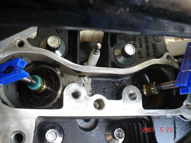
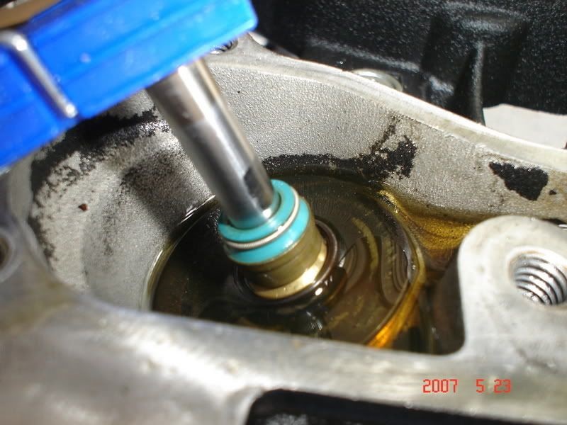
| Head ready for testing. 11) | Oil poured in and draining. 12) | Oil level at the intake valve when it starts to drain to the exhaust side. 13) |
 | 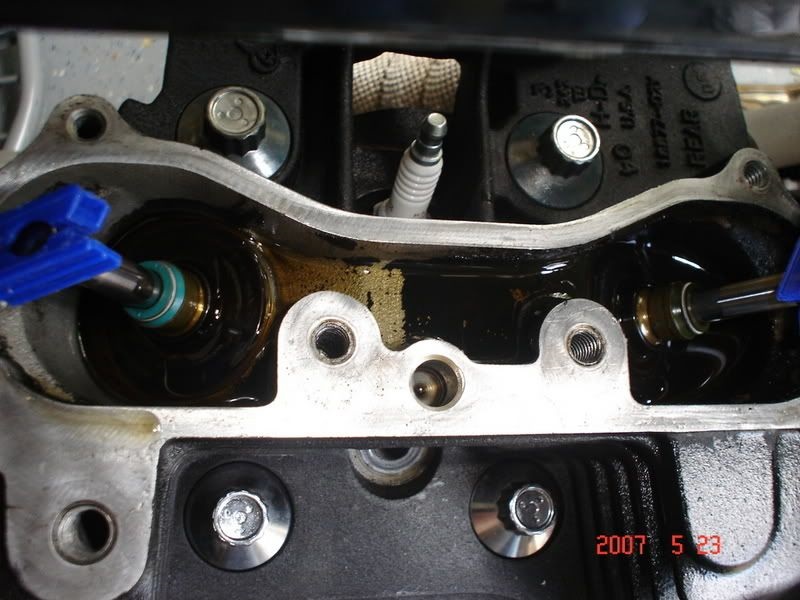 |  |
The oil you see in the first pic below is held there by the spring seat.
At no time did the level become so great as to submerge the exhaust valve seal.
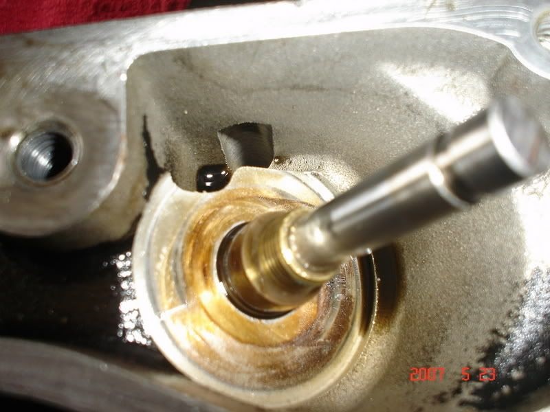
You might be able to dress up the entrance to the exhaust drain with a burr to enhance flow to the drain.
But it may not be necessary as it does drain really well and the spring seat above it might negate any advantage you got from doing so.
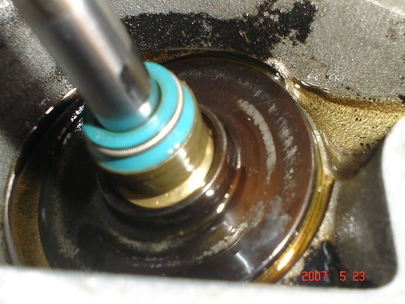
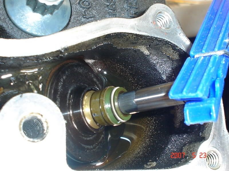
| Oil level at the exhaust valve when draining stops. 14) | This is as high as the level got at the intake valve. 15) | This is the drain in the exhaust pocket. 16) |
 |  |  |