Table of Contents

REF: Engine Mechanicals - Sub-05E
Adding a Vent Between the Oil Tank and the Cam Chest
Article by Deimus of the XLFORUM 1)
Also see Crankcase Ventilation in the Evo section of the Sportsterpedia for pics and info on the OEM breathing system.
Background:
This mod was attempted to improve crankcase pressure venting for more efficient oil flow, lower oil temps and neutral pressure inside the oil tank on 04 and up Sportsters.
(even though the vents are different on earlier Sportsters, engine breathing is the same concept)
Before this mod, the tank oil gauge would readily hit 250°F, the oil would look foamy after running hard and the top end was much noisy.
The idea was to install a PCV valve inline on the vent line from the oil tank to the cam chest in addition to the head vents.
Results of this mod:
This mod was deemed not to work properly at high RPM as oil would back up into the added vent and cause higher oil temps.
It was eventually reversed with a solid hose replaced as in the OEM configuration.
Then the cam cover was fitted with a vent and PCV valve which did work.
However, others have done this mod with positive results. Other engine mods, specific setups and riding style will vary results.
Click here to view that article in the Sportsterpedia … Installing the Ultimate Crankcase Vent
Installing the PCV in the Vent Line
Note, use at your own risk!:
Again, this mod was proven to Not work on the subject engine.
The process is detailed below for historical and educational purposes only until proven or revised!
- Parts:
- 3/8“ barbed tee.
- 2 feet of 5/16” fuel line (5/16“ was used since it is more flexible than 3/8” line)
- 6 small clamps
- A high quality inline PCV valve.
Automotive PCV valves do not completely prevent new air being sucked back in through the vent.
(as well as not being able to respond as quickly as our engines need).
The inline PCV valve used here was from ET Performance part number ETSE.
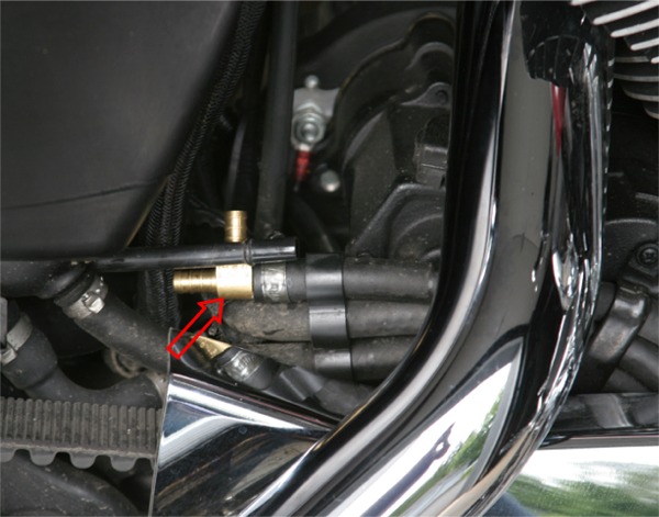
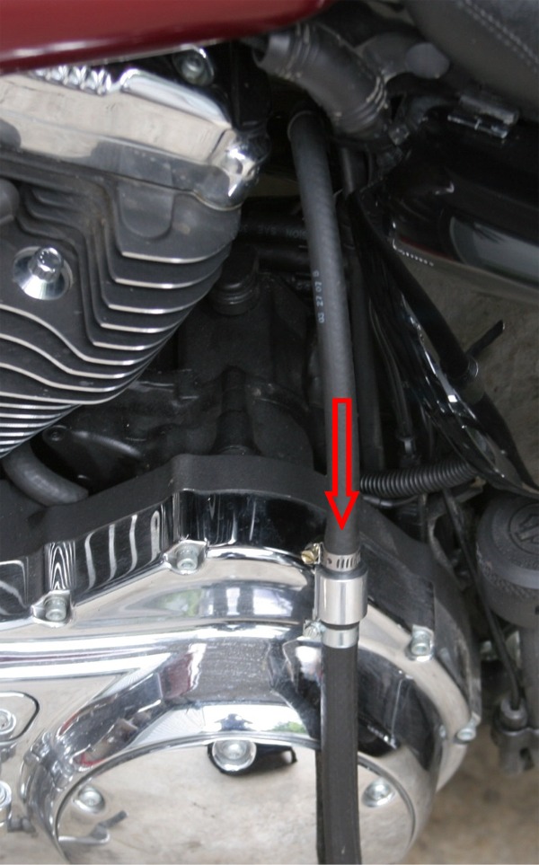
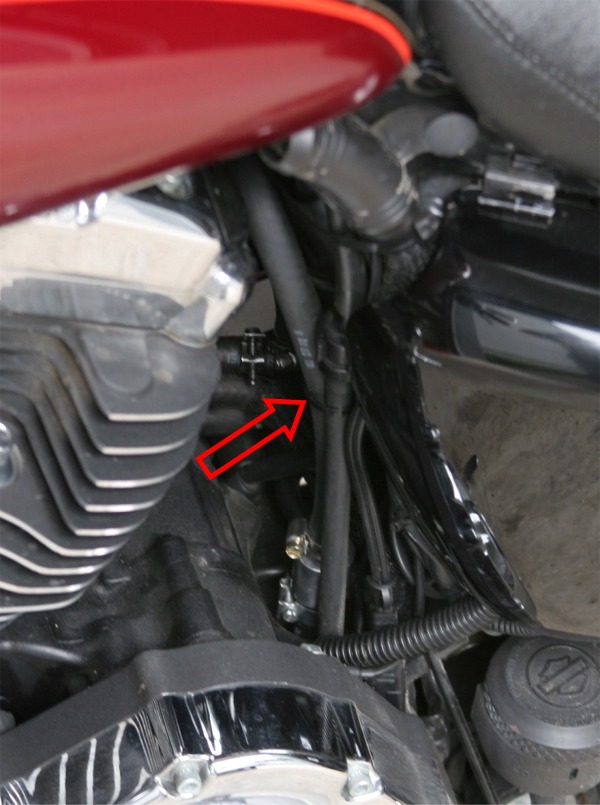
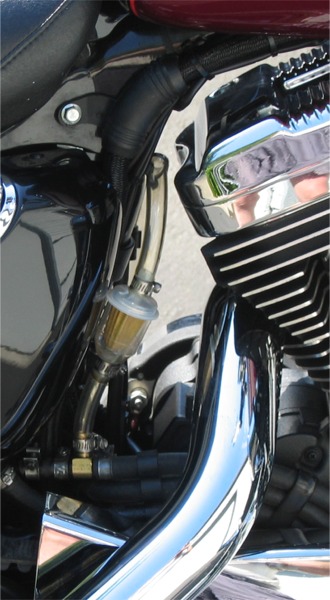
You will find the oil tank/cam cover vent line on the right side of the engine.
It will be the top line of the three you see running back to the oil tank from the engine.
It will be the only line that includes a plastic tube section.
The first thing you will do is to separate the vent hose from the plastic tube section.
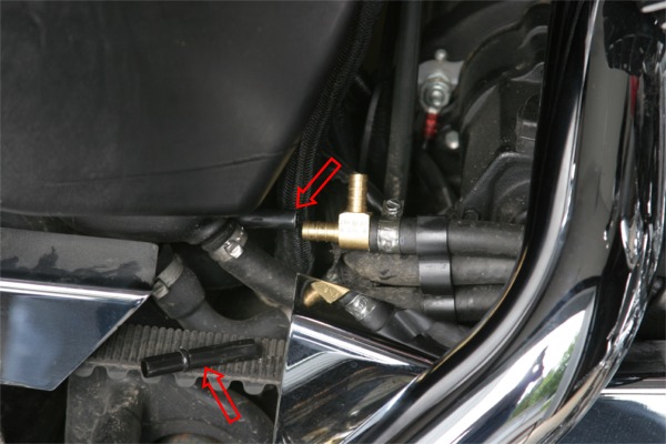
| Install the tee in the hose with the tee pointing up. | The plastic tube needs to be clipped. The excess piece is sitting on the belt. | Connect the tee with a short piece of 5/16“ hose. Connect the tee to the plastic tube. |
 |  |  |
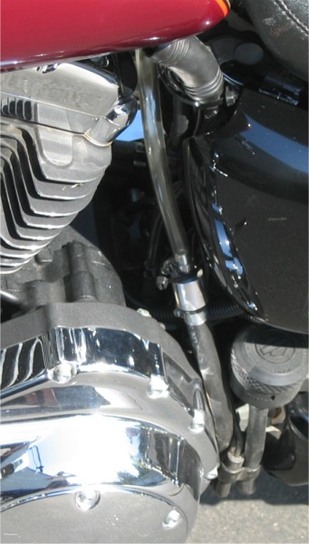
Next, loop the new vent line up the frame tube and then run it back down.
- The length of hose going up will give an opportunity for any oil mist in the air being vented to collect on the insides of the hose.
(and drain back down staying inside the engine) - The vent inside the oil tank is on the left side of the tank.
- When the bike is on the jiffy stand with the engine idling, if the oil level is high then oil might find its way down the vent line.
By having the loop in place, the tee is not the high point so the oil should drain down into the cam chest and be recycled back into the oil tank.
However, if the oil level is too high then the excess oil will be pumped out of the vent. - This will only expel the excess oil so don't overfill your tank.
- A wire tie used to secure the loop so it will stay in place.
The wire tie is actually connected to a pair of wire ties connected together then attached around the frame tube.
Otherwise there's nothing here to tie the hose to.
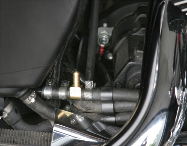
| New vent installed and secured. | ||
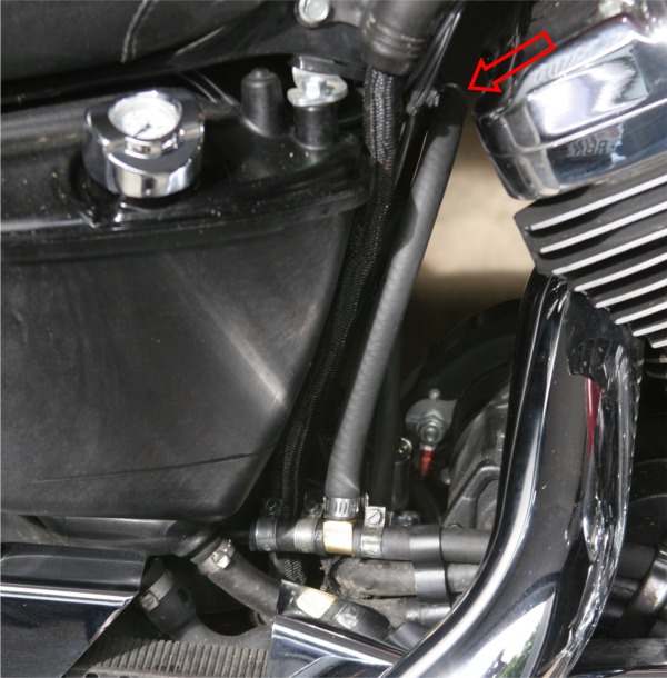 |  |  |
The new vent line is hardly noticeable and stays tucked close to the frame tube.
By locating the tee close to the frame tube and trimming the excess from the plastic tube instead of from the original hose.
| Original finished product. | |
 |  |
First Ride report: 2)
The trip was over 2,200 miles consisting of cool areas, warm areas, and very hot areas as well.
So all conditions were encountered. The bike ran well the entire time. It never got hot nor foamed the oil.
However, the oil consumption was not solved. Every time I stopped, drips of oil came from the vent hose.
And my back tire and wheel definitely showed that the oil consumption was going out the vent.
I got over 50 miles to the gallon always. I would hit reserve between 175 and 185 miles on the trip odometer.
So I'm very pleased with how the bike ran. I just need to figure out a way to remove the oil from the air being vented.
The original design of the vent with only the PCV valve did not solve the oil usage problem.
The bike ran great but it constantly vented oil a drop at a time. I added 3 quarts of oil during the 2200 mile trip.
First attempt to remove oil vapor - terrible idea:
The first idea was to slow the vent air speed so the oil might settle out of the vent stream.
(This is how sediment settles out of river water. The river widens, the flow slows and the sediment settles out)
Since the vent already runs into the oil tank;
You'd think you'd be able to use the large air space in the oil tank to slow the vent air speed enough to allow the oil vapor to settle out.
The vent tube inside the tank is at the top.
You can remove the vent line from the tank and attach a piece of hose to the tank fitting.
Then blow air into the hose and it shouldn't bubble in the oil tank.
There should be a hiss from the air coming out.
This means you can remove the tee and let the cam chest vent line run straight into the oil tank.
Then drill one hole in the tank for the exit vent line.
Result:
With a hose attached and the PCV valve on it, when the brakes are applied as in stopping, oil would puke out of the vent.
Do not drill any holes in your oil tank. The air space in the oil tank isn't always air.
During the normal course of riding, oil sloshes all around in there so any exits you create will eventually be submerged with oil.
So the hose was removed from the tank and the hole plugged and the tee was re-installed in the vent line.
Second attempt to remove oil vapor - better idea:
This seemed to work better. Two changes were made.
The first was to remove the head breather banjo bolts because these leaked some on the trip.
Two solid 1/2” bolts were used in there place.
This is also a possible cause for some air to come back into the engine to be recycled and re-vented.
(any leak out of the crankcase is a potential source of air being sucked back)
Next, a clear paper media fuel filter for small engines was added to the vent mod between the tee and the PCV valve.
The fuel filter is used to separate the oil out of the vent air stream and installed right above the tee.
Clear tubing was used for a visual to see the results.
Result:
After 100 miles on this setup, the vent pipe remained dry and it was shiny inside before the filter.
Any oil that collects out of the air stream can simply drain back into the engine.
The engine continues to run like it did on the trip… that is, quieter than before adding the new vent as well as running about 200 degrees.
With the added inline fuel filter to strain out the oil vapor from the vented air, no drips were seen in the 100 miles ridden.
And with the fuel filter being placed before the PCV valve, the oil should remain in the engine. 3)
 |  |
Result: 4)
The paper element in the fuel filter became saturated with oil after 150 miles of riding and the vent hose connections began to leak.
So the paper element filters are not appropriate for this application.
With the filter changed to a mesh type:
A glass inline fuel filter was used to replace the paper element filter.
It contains a mesh filter and it can be opened so the media can be cleaned or replaced.
Result:
The first 350 miles of the ride were along back roads with medium speeds. The bike ran great and didn't consume any noticeable oil.
The last 200 miles were open highway and Interstate at 75 to 80 mph with strong gusts of head winds.
Again, the inline filter was overwhelmed, the hose connections leaked and more than a quart of oil was lost.
This suggests that the vent in the cam cover becomes saturated with oil when the engine is being run hard.
Cam cover vent baffle added:
Caution: The rocker box should be loosened / removed before removing the cam cover to prevent damage to the cam bushings.
See Removing the Rocker Boxes in the Evo section of the Sportsterpedia.
See also Removing the Cam Cover.
This was done to reduce the amount of oil that is making it into the vent line itself.
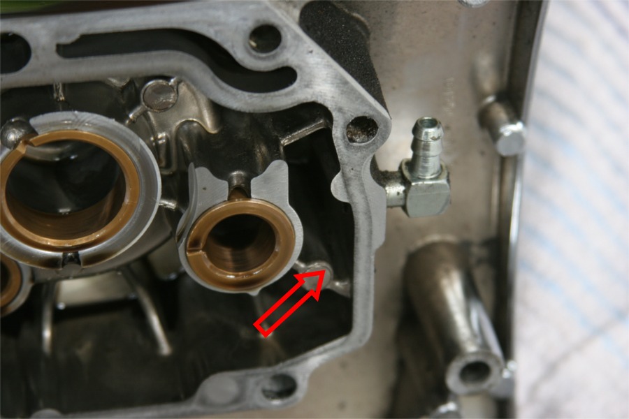
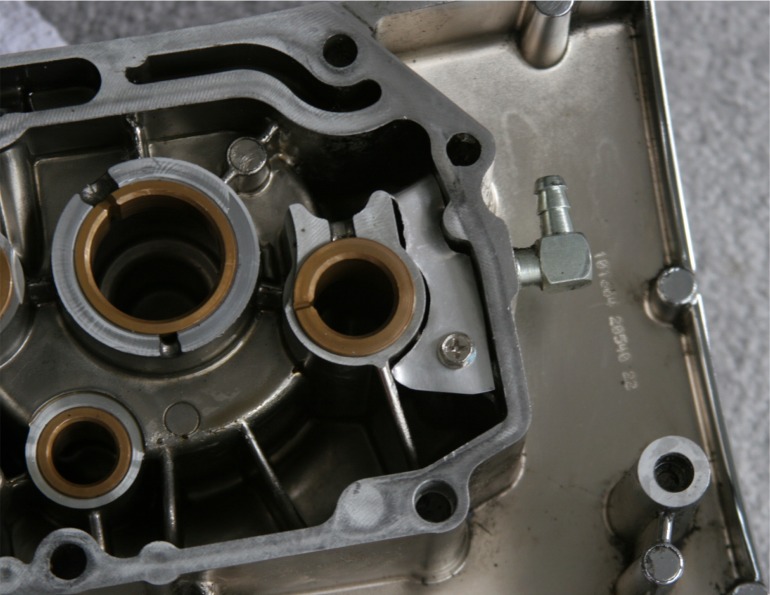
The oil tank vent fitting is located right beside one of the cam gears.
It has its own (inlet) compartment from the oil tank.
This compartment was wet with oil when the cover was removed.
Notice that the top of this compartment has a notch.
#1 cam gear rotation is counter-clockwise looking at the inside of the cover (as indicated with the arrow in the first pic below.
Under load, this could sling oil up and then drain down into the vent compartment.
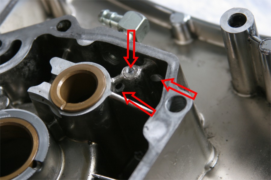
| Vent location inside the cam cover. | A screw hole and two drain holes drilled. |
 |  |
| An aluminum baffle was fabricated. | Finished baffle shown. |
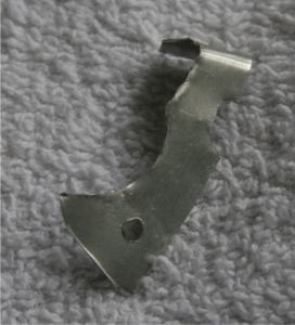 |  |
Result:
The current modified state did fine on short test rides.
However, on the interstate at continuous speeds of 80mph, engine temps hit 245°F for the first time since the vent was installed.
(presumably caused by the restriction from the in line fuel filter clogged with oil)
Additional changes:
Two more changes were added:
First, holes were poked in the mesh filter element with a needle to help keep it from stopping up.
Before doing this it was hard to blow through the filter and after doing this, air flowed freely through the filter.
Second, a new oil baffle was made to go inside the cam cover to protect the vent opening from oil splash at higher RPM.
The new baffle looks very much like the one in the original photo only it was made more precisely so it fits tighter.
In addition, Permatex black silicon was used to seal the edges of the baffle.
Now the only openings to the vent in the cam cover are the two holes drilled in the bottom of the vent compartment.
Result: 5)
Previously when the inline filter was restricting the air flow, the engine oil temp readily hit 245°F.
Now with the inline filter free breathing, the engine oil temp hardly got over 200ºF.
Clearly the engine needs to be able to breath in order to avoid high oil temps.
As to solving the problem of oil dripping out of the vent line, no solution has been found yet.
With the inline glass filter and clear hose, you can clearly see oil gurgling inside.
Conclusions from this mod
Installing a PCV on the oil tank vent line did not help in creating more efficient flow of oil in the subject engine.
In fact, it increased operating temps and didn't stop the loss of oil.
Having a check valve is part of the solution. 6)
Allowing a pulsing of air into and out of the engine can only compound the oil venting problems at best.
A worse effect is that the presence of that air in the crankcase on the down strokes of the pistons will cost some engine power as these gasses are compressed.
The engine is working harder with this fix to sustain 80mph than it did to sustain 4000 rpm in 3rd going 60mph.
This should explain the temps in the different situations: 7)
Running 4000 rpm going 60mph, the temp was 220°F.
Running 60mph in 5th gear and the temp was only 200°F.
Running 80mph in 5th and the temp was 250°F.
These three examples were all sustained runs of 15 minutes or more in each situation.
The location of the factory vent fitting in the cam cover that was used for the “Tee” vent mod is very close to the cam gears. 8)
The Tee mod worked pretty well except for high speed cruising.
So much oil is being slung around that fitting in those conditions that adding a vent there will be oily.
Based on these findings, adding the custom vent in the cam cover along with an oil splash guard is the better way to go.
That mod is detailed here: Installing the Ultimate Crankcase Vent