Table of Contents

REF: Engine Mechanicals - Sub-05I
79-85 Breather Vent Mod - Adding a Secondary Vent Hose at 6:00 Position
See also in the Sportsterpedia:
- Breather Venting / Relocation (especially the sub documents at the top of the page)
- Using / Diagnosing with a Slack Tube (Manometer) (to test crankcase pressure)
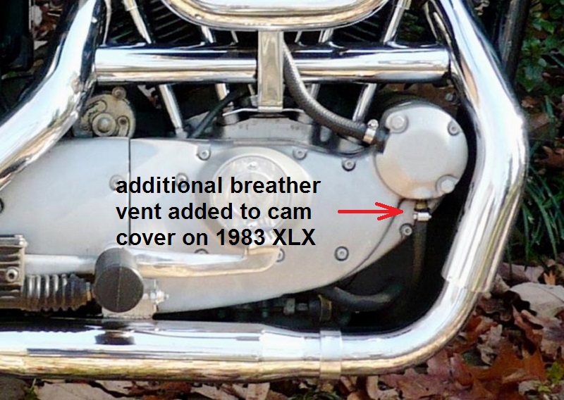
- 79-85 cam covers can be modded to accept a secondary breather vent hose.
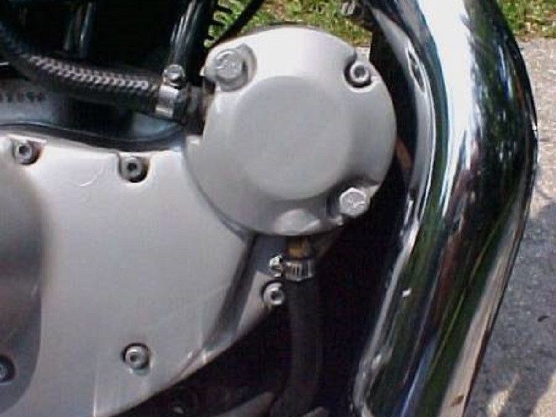
- There is a plugged hole at 6 o'clock below the 10:00 vent line (to A/C) in the cover (when looking at the cover installed).
- Older bikes were originally plumbed into the A/C from a vent in the 6:00 position with a metal tube as a vent dumping to atmosphere. 1)
It would mist a small amount of oil while riding but not a major oil slick. - 79-up Ironheads can benefit from removing the 6 o'clock plug from the cover and adding an additional breather hose there.
It is said to allow the crankcase pressure to evacuate faster, resulting in the motor being a little more free-revving.
A side benefit is that it will largely eliminate the “oil in the air cleaner” syndrome, assuming the original breather is left in place.
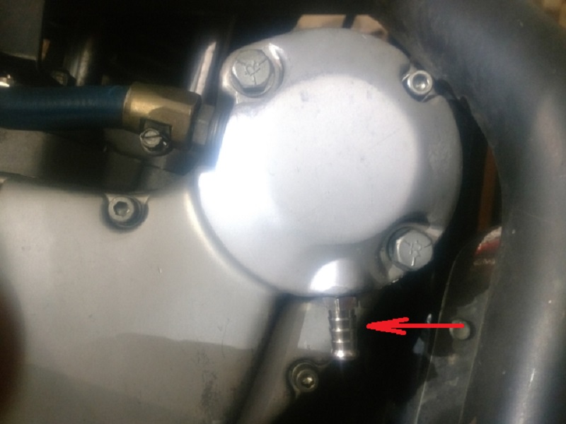
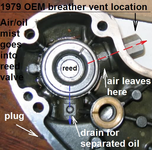
You can terminate the extra breather hose under the engine. However, it will drip a spot or two of oil there when parked or after a “spirited” ride. - In the pic below, you can see where the oil normally drains back into the engine.
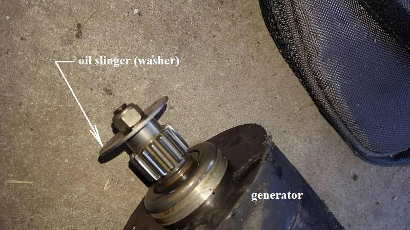
Air and oil mist (oil that gets past the oil slinger on the generator) gets blown into the reed valve.
In the cavity behind the reed, oil drops out of suspension and drains back.
At the same time, the air is purged out the vent hose.
- Considerations:
- With the cam cover off, you can see a tiny hole drilled at the bottom of the cavity that by-passes the breather vent.
This hole drains separated oil that collects in the cavity back into the motor.
Be aware that opening the bottom port in the breather can affect the oil drain-back feature.
A hose connected to that position can still dribble oil out in small droplets from time to time.
If the motor is pushing oil out the breather, you may have a ring seal or other problem.
Adding a second breather hose will not fix that. It could be a bad breather valve causing that also. - Engine crankcase pressure is designed to have a slight vacuum with the engine running.
That is a little confusing as it is a variable (mean vacuum) pressure measurement based on ring seal and RPM.
You'll have the most vacuum at idle. As the RPM rises, you'll have less vacuum.
Around 5000-5500 RPM, ring flutter will turn the vacuum into a positive (pushing) charge. - All you are affectively doing with this mod is enlarging the vent outlet size past the breather valve.
Enlarging the vent size can raise vacuum and increase ring seal. (see Theorizing the Affects of the Second Hose below)
Note: if your spark plugs get real black and cruddy looking, you might want to remove the internal breather valve and install and external breather valve. - It's never a bad idea to periodically test crankcase vacuum with a slack tube (manometer). That way you know what the mod is doing to the inside pressure.
See the link at the top of the page. - If installing an external breather valve.
If you decide to go this route, remove the internal valve as it will also change crankcase pressure with 2 valves in line.
Then, you might want to consider installing something like the external Krankvent or others.
Click here to see the Converting Head Breathers to Cam Chest Breather page in the Sportsterpedia.
That page is for an Evo conversion to cam chest breathing but the Krankvent and plumbing is shown. - Do not install a filter on the end of the vent hose.
It's not at all necessary as there is normally no vacuum on the outside of the breather valve (just a slight escape of crankcase gasses).
(unless your breather valve isn't working properly)
The filter adds resistance to the vent pressure coming out of the engine. This resistance can add to goop in the line / filter later.
A stopped up filter can also increase the vacuum inside the engine, which on a street bike, translates to weeping gaskets.
Click here to see more on installing a vent line filter.
- Installing the extra hose:
- You do not need to remove the cam cover to do this. The 6:00 o'clock position has a 1/8“ NPT Allen head plug.
(same plug as on the corners of the rocker covers)
- Simply remove the plug and replace it with an 1/8” NPT hose fitting and hose.
Theorizing the Affects of the Second Hose
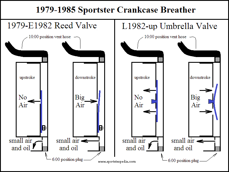
- In 79-up engines, there should not be a time when the breather vent is pushing out air except on the initial downstroke.
- When you first fire up, air in the crankcase is pushed out the breather valve.
Then the breather valve closes on upstroke and reverses the air pressure to a negative (vacuum).- If the breather valve is working right, there is no more air being pushed out then.
And the push - pull condition of air pressure is between the valve inward. - If the vent is pushing out air frequently during operation, the valve is not working properly.
With a bad breather valve, air is push-pulled from the vent area past the breather and involving extra air intake to the system.
- The breather valve is in a built in pocket in the cam cover (see the pic above).
- Forget about the breather vent for a second. Air/oil mist enters the pocket and flows past the valve.
- Just past the valve (between it and the vent outlet) is another smaller chamber.
That is the final separation chamber for air and oil.
Oil droplets fall out of suspension there and down into a small hole between the valve and the cover which leads back into the gearcase. - Air in that small chamber is sent out the 10:00 vent hole. The 6:00 plugged hole comes out of that same final small separation chamber.
- So the two vents are coming from the same chamber and both are past the breather valve and final separation chamber.
However, one caveat may be if the 6:00 hole is part of the bore for the drainback hole. - The bottom of the separation chamber where it says “reed” in the pic below is not really the bottom of the chamber.
There is a space (final separation chamber) behind the reed (between the reed and the cover).
That is where oil droplets are pulled back into the gearcase that make it past the reed.
Vacuum in the bottom end pulls oil from that chamber back into the gearcase. - Since both vent holes are past the breather valve, there is no need to add a valve on the 6:00 hole. It already has one.
- Adding the extra vent hose simply removes some of the restriction working back against the valve (every action has an equal and opposite reaction)
You just have to make sure that valve works. One way to do that is to test it with a slack tube.
Here is a pic of the internal reed valve on a 79 model on the left.
You can see the 10 o-clock fitting and the 6 o-clock fitting both enter the same cavity.
The oil slinger is the big fat washer on the end of the generator in the (R) pic below.
 6)
6)
- 1977-2003 Sportster engines are very similar as far as crankcase pressure is concerned. 1979-1985 models may have more or less vacuum given piston and seal differences etc., but they can be compared.
- The standard conversion from PSI to Inches of Water is 1 PSI = equals 28“ of Water Column (overall vertical movement).
- Manometer testing on a 1998 XL1250S resulted in -0.75 PSI of crankcase vacuum and that is an average pressure, not an absolute pressure.
Now figure just how little restriction it takes on the vent side to bottle up -0.75 psi.
You can probably sneeze harder than that. But that does change things inside the motor.
- This also has to do with how fast or to what state the breather valve operates.
- Added restrictions on the vent side of the valve affects it's operation.
We talk of the piston up and down movement as if you could watch it rise and fall.
And consequently visualize and measure pressure in it's actual state of stroke position. - The internal pressure is ever changing + to - with piston up and down movement. It doesn't keep a steady vacuum but rather a mean vacuum.
- Example: With both pistons traveling up and down at different times at idle of 1000 RPM;
Means that forces to and fro are acting on the breather valve at possibly 4000 RPM.
One piston is at BTDC and is about to build vacuum on the way up at the same time the second piston is coming down.
So there is an overlap at TDC and BTDC that should be the point where pressure is most stable.
Now add the fact that the crank is at 1000 RPM.
Instead of a lab test of how much pressure builds on up or down stroke, this is the reality of the speed in which pressure changes. - The faster an object moves back and forth, the less turbulence is created and more of an average pressure is created between strokes.
- Coming back to the breather valve, it's fluctuating in tandem with piston movement and potentially 4 times faster.
It can't react as fast as the pistons do if the outlet downstream is restricted.
The more the restriction, the more it “flutters” close to it's center of travel (the breather valve travels both out and in).
This means that instead of reducing vacuum with more restriction, (which does reflect the testing results);
It may be better put as not allowing the breather valve time to fully close with more restriction on the vent. - So we have mechanical limitations to how much vacuum is created and we have situational conditions that change those limitations.
- Adding the extra hose removes some of the restriction working back toward the breather valve.
It allows the breather to work more efficiently. Again, this is assuming the breather valve is in good working order.
Moving the 10:00 Hose to the Bottom to Use an Aftermarket Air Cleaner
- Moving the line is relatively easy.
- Remove the upper hose (10:00) and fitting. Install a 3/8” NPT pipe plug in it's place.
Then remove the lower (6:00) 1/8“ NPT pipe plug, install a hose barb fitting and a hose. - Both upper and lower vent holes access the internal valve equally and function the same way.
- Considerations.
- However, plugging the upper 3/8” outlet and using the lower 1/8“ outlet may reduce crankcase vacuum.
You also may get more oil drips simply because it is at the bottom (gravity). 7) - With this mod, you are reducing mean vacuum in the crankcase. This WILL affect crankcase pressure.
Reducing the outlet size creates less mean vacuum in the crankcase (more positive pressure).
This is good for oil scavenging but not as good for ring seal.
However, if you are dealing with oil weeping or leaking at gaskets / seals, this may help to lower vacuum that may be creating it.
The best advice is to repair / replace the breather valve and / or bad gaskets or seals.
Repeated need for replacing these things is a good indication of too much vacuum.
Here is a 1980 XLH with the 10:00 fitting plugged and the 6:00 hole being used to vent the crankcase.
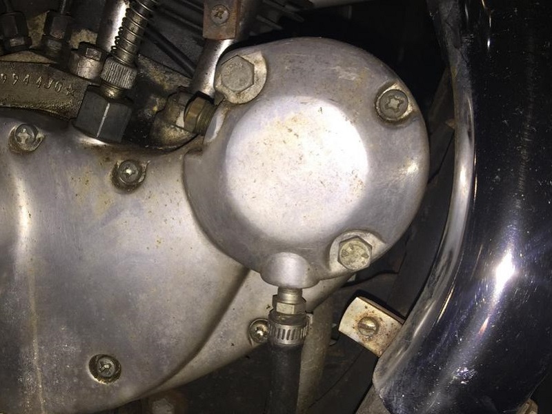 8)
8)
2)
drawing by Hippysmack
5)
photo by 83XLX of the XLFORUM, annotated by Hippysmack https://www.xlforum.net/forum/sportster-motorcycle-forum/sportster-motorcycle-era-specific-and-model-specific/ironhead-sportster-motorcycle-talk-1957-1985/128453-crankcase-breathing-cycle/page3?t=1332902&page=3