Table of Contents
This is an old revision of the document!

REF: General-MSR 07
Diagnosing Catastrophic Engine Failure in Evo Engines
Determining the exact cause of an engine seizing up is often not that easy.
Its kind of a cascading problem since when one part fails, other parts are damaged also and the hunt begins uncovering similar causes and affects.
It could be described as a “Chicken or the Egg Syndrome”.
Spun cam bushings are usually thought of as a poor oiling issue.
This might cause enough heat to expand their bores and loosen the bushings, allowing them to seize to the spinning cams.
Possible Causes of Spun Cam Bushings
On the cam bushings in either the cover or cases you have 3 different metals with different expansion rates so what really happens? 1) 2)
- Installation error. These items will begin a natural degradation of improper oiling/ heat related failures:
- The OD of the bushing should match the ID of the bore before installation. That has to be measured before installing the bushings.
- Bushings not reamed to proper clearances using the service manual.
- Bushings not properly seated during installation. Each bushing has to butt into the cam wall. That sets the proper side play.
If the bushing doesn't install against the cam wall, side play is to little which creates heat during operation. - Camshafts and bushings not properly lubed for initial start-up.
All cams and their associated bushings should be slathered in thick lube during installation else initial startup could create enough heat to spin the bushings.
- After engine is broken in:
- Cases get hot and shrink the bushings.
- Bushings get too hot and stick to the cams then spin in the case.
- Camshaft to bushing clearance out of spec.
If there is too much clearance, the cams can turn out of center and bind against each other causing enough heat to lock the bushings on the cams. - Cams get hot and stick the bushings then spin in the case.
- Too much camshaft to bushing clearance.
- Contamination of the oil.
- Wetsumping and other oil system related issues, clogged oil lines etc.
- Locked up oil pump or worn or out of service limit geroters.
- Crankshaft Failure allowing metal grit to get splashed between the bushing and camshaft.
- Sheared pinion shaft key under oil pump drive gear stopping the pump from working.
- Sheared pinion shaft key under pinion gear allowing it to turn and change overall cam timing.
This results in a valve slapping a piston and the force travels back to the cams knocking the shafts into a bushing and spinning it.- When the valve opens, pressure is exerted in 2 directions (cam to valve and valve to cam). 3)
The valve opens due to that being the weakest point (sprung) when the lobe lifts. The cam has no springs.
The sudden jolt of the piston hitting the valve can transfer back down the path.
(and push the spinning cam's shaft against a bushing it's not suppose to be touching while spinning)
Thus catching and spinning the bushing (no oiling issues to seize the bushings)
- Repair. When the bushings spin in the cases, they don't leave a perfectly round bore. As they spin, they rip/ream some of the bore I.D. and may move the bore center.
Finding that center with oversize bushings should be done by a qualified machine shop. - Dark Horse Crankworks offers a replacement service for spun bushings. 4) Click here for the link.
They can also upgrade them to bearings like the 4-speeds had. However, the cost of either service might approach the cost of a new set of cases.
Check with them and check with your dealer. New cases will be stamped with your VIN.
You literally have to turn in your old cases, or at least the portion of them that has the VIN, to buy new ones. - Easter MC sells oversized cam bushings to replace bushing number (25598-91). 5)
+.005“ oversized bushing (A-25598-91+5). Click here for the link.
+.001” oversized bushing (A-25598-91+1) Click here for the link.
Affects of a Spun Pinion Shaft Gear
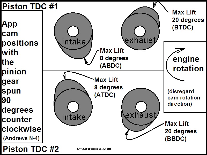
The drawing below shows 2 valve trains at the same time on the same cylinder using Andrews N-4 cams. 6)
It represents cam timing/valve opening and closing times in respect to piston position.
The blue directional arrow represents engine rotation direction. The orange and green lines represent cam/valve lift and / or position at the specific crank locations in degrees.
So you are seeing the piston movement in degrees and the position in degrees of each cam lobe. Max lift is exactly in the middle of each opening and closing times of each valve.
You'll see in this drawing that normally, at TDC and BDC, max lift on the cams will not happen at either location.

Now with the pinion gear rotated 90º counterclockwise, the same exact opening and closing times happens in the valve train.
Cam timing remained the same respectively but they just happen 90º later than they were originally.
A notation was made on the drawing to mark the approximate point of max lift for each valve.
There is more to max lift than just the valve opening. But this is for example only to illustrate where the highest lift might occur during TDC.
As you can now see, max lift will occur at or near TDC. TDC happens twice per 1 revolution of the cam/valve opening.
So in this example, the degree wheel below turns 2 full revs to make 1 full rev of each cam, thus valve train.
In the drawing below;
The intake cam lobe center (point of max lift) is now resting at app. 8º after BDC.
On the next TDC event (360º of crank movement), max lift (180º of cam movement) on the intake valve will occur at 8º after TDC.
Next TDC event, max lift will be back at 8º after BDC.
The exhaust cam lobe center (point of max lift) is resting at app. 20º before TDC.
On the next TDC event (360º of crank movement), max lift (180º of cam movement) on the exhaust valve will be app 20º before BDC.
Next TDC event, max lift will be back at 20º before TDC.
So in this example, the intake valve should take the first hit before the exhaust valve would due to the proximity to the piston during rotation.
Note: all you have to do is turn this drawing upside down, change BDC to TDC and you'll see that the intake valve is at or near full extension when the next TDC rolled around.

The drawing below is in conjunction with the drawing above to visualize cam lobe positions.
Disregard cam rotation direction as the drawing is showing cam lift / valve opening.
This is simply to show which direction the cam lobes face in the spun pinion gear scenario.
Crankshaft Out of True
See Measuring Pinion Shaft Runout in the REF section of the Sportsterpedia.
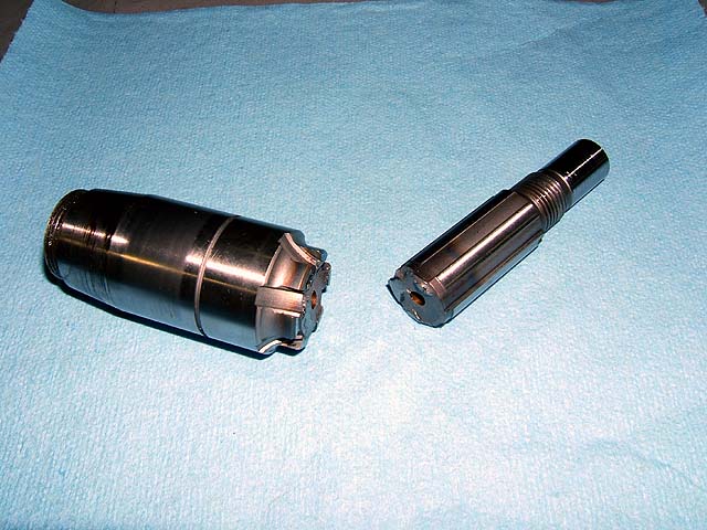
Here's the worst symptom of an out-of-true crank. The pinion shaft snapped. 8)
This particular one happened at roughly 180mph. I had qualified the bike at 207 and change, and was on my backup pass.
Everything was going smooth, I had it wound out in 4th, I eased off the throttle, clicked it into 5th, eased out the clutch and rolled back into it and …
Nothing. The fire had completely gone out.
I said a bad word. I pulled off the course and noticed the timing rotor wasn't turning (it's exposed on this bike).
One time several years ago, HAMMER Dan called me from a race he was at, out east somewhere.
He was all in a panic because it was Friday afternoon and he was sure he had bent a valve and wanted me to overnight him some valves with Saturday delivery.
After chatting with him a bit I convinced him to look a little deeper before we started jumping through hoops … he got a rocker box top off and sure enough, nothing was moving.
He had done the same thing.