Table of Contents
This is an old revision of the document!

EVO: Suspension - Sub-03A
1998 1200S Swingarm Bearing / Bushing Inspection and Replacement
Prep Work
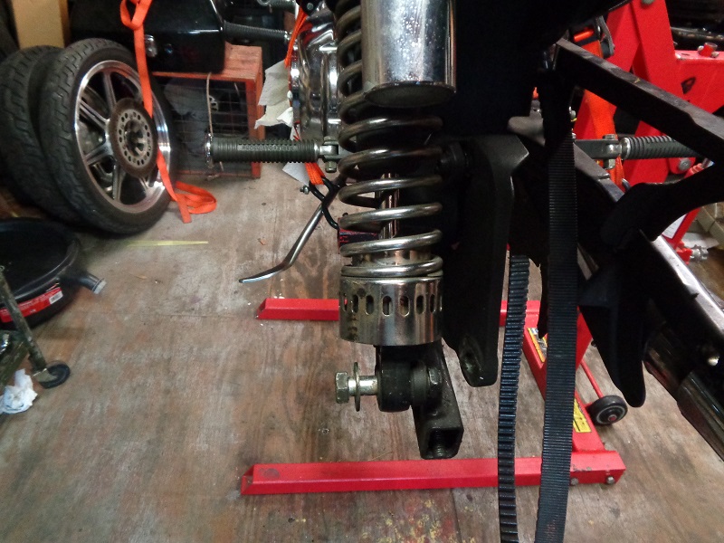
The rear tire and lower shock mount(s) must come off before you can remove the swingarm.
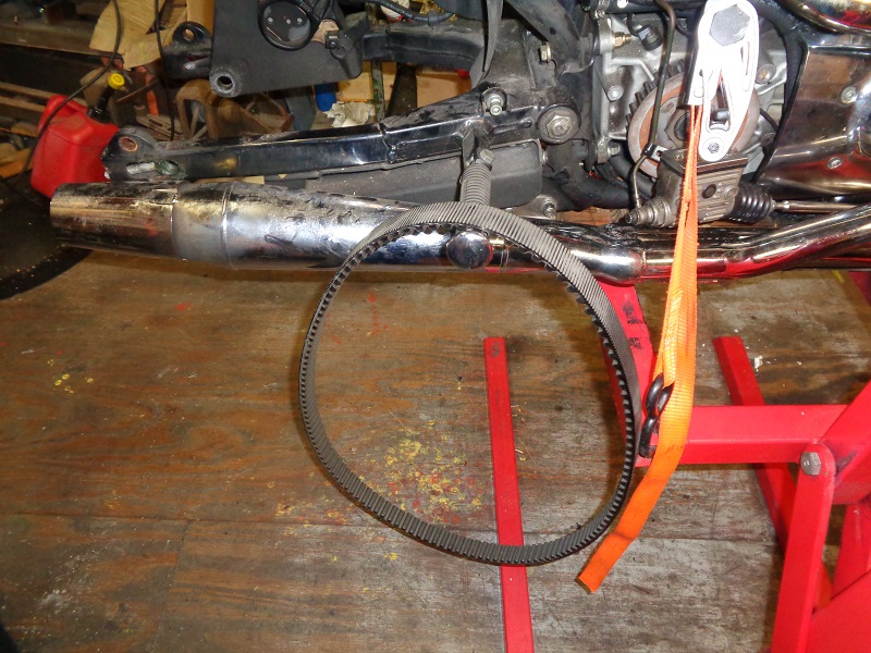
The belt doesn't have to come off but has been removed below.
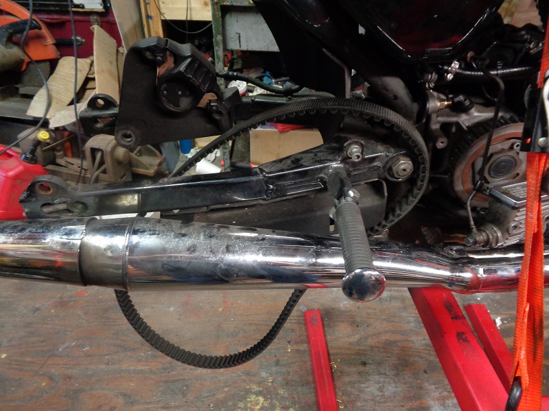
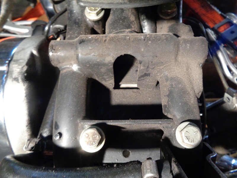
| With the belt guard removed, the belt just slides around and out of the swingarm. 3) | ||
 |  |  |
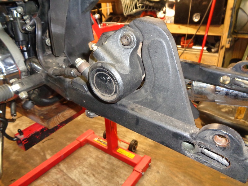
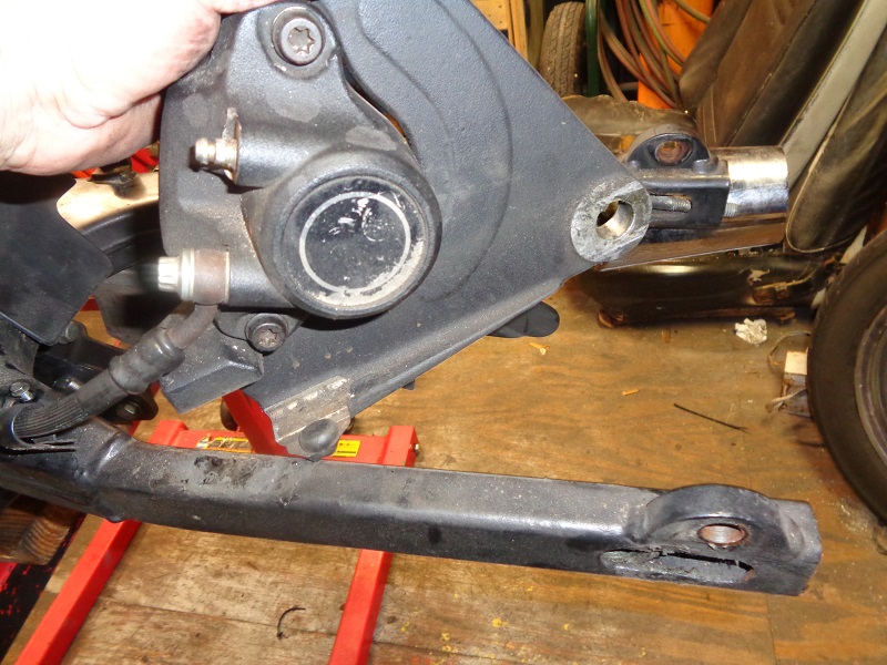
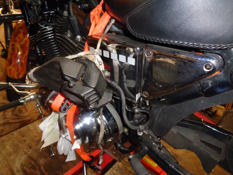
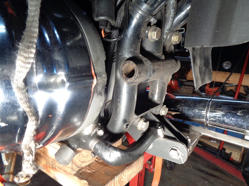
| The 98 style brake caliper still on it's bracket simply lifts off with the wheel removed. It can be hung from the bike out of the way for swingarm removal. 4) | ||
 |  |  |
Removing the Swingarm
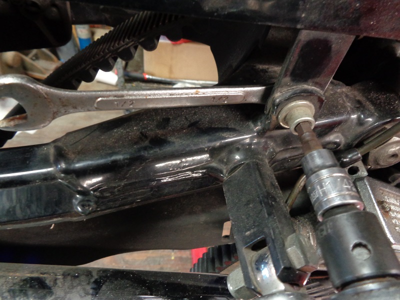
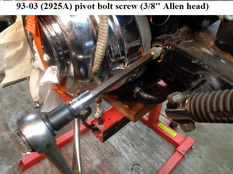
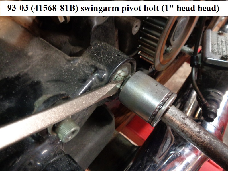
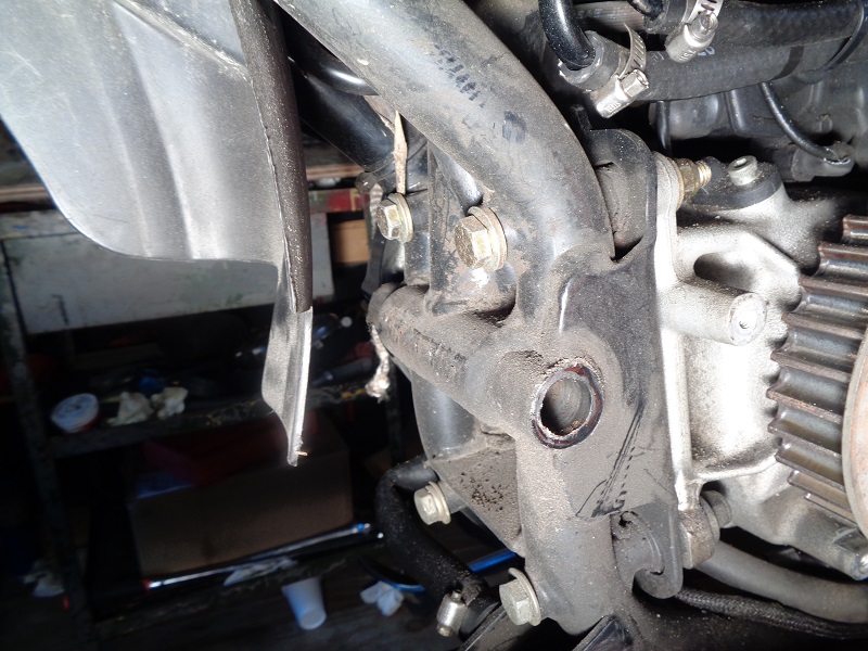
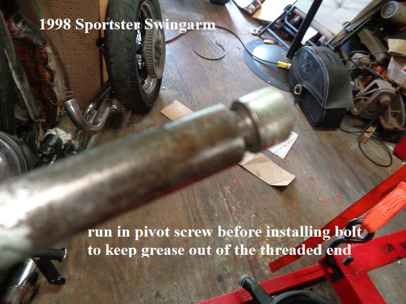
Remove the pivot bolt screw (left side) and turn the bolt (right side) a few turns to loosen it up.
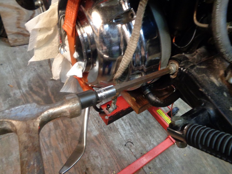
Put the pivot bolt screw back in a few turns and whack it with a hammer to initially drive the bolt out toward the right side.
Then use a screwdriver to pry the bolt outward while turning the screw. Continue turning while giving up pressure on the wrench to back the bolt out.
Or you could use a drift and a hammer on the left side to punch the bolt out but be careful not to damage the internal threads of the bolt.
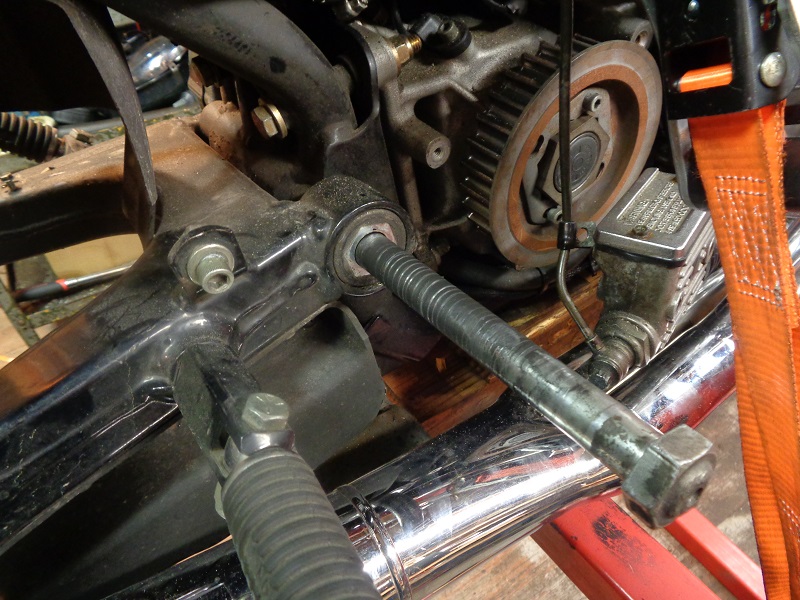
The sleeve on the frame that the bolt runs through has a hole in the middle where water can get onto the middle of the bolt and cause rusting.
So you may have to get creative when knocking the bolt out (which is the reason for turning the bolt out instead of knocking it out).
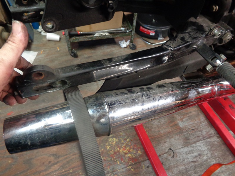
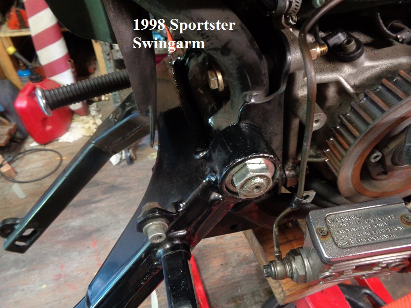
Once the bolt is removed, the swingarm just falls away.
Inspecting the Swingarm and Parts
Note: The maintenance schedule in the FSM suggests to inspect the pivot shaft and swingarm bearings every 5,000 miles.
Then to lube the swingarm bearings every 10,0000 miles. 9)
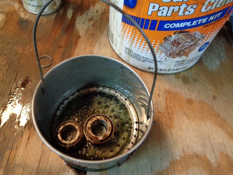
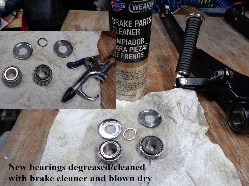
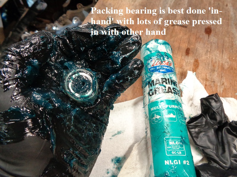
However it doesn't take but just a couple minutes to hose down the bearings with carb cleaner, blow dry and repack them with fresh grease.
(since you have the pivot bolt out for inspection anyway)
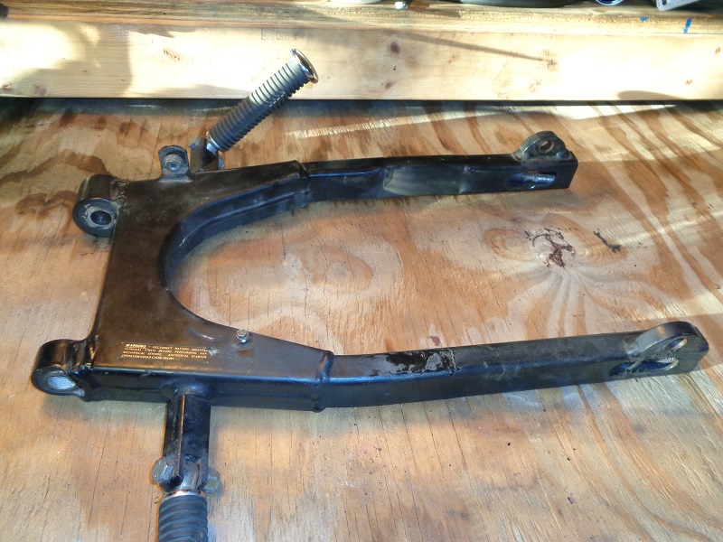
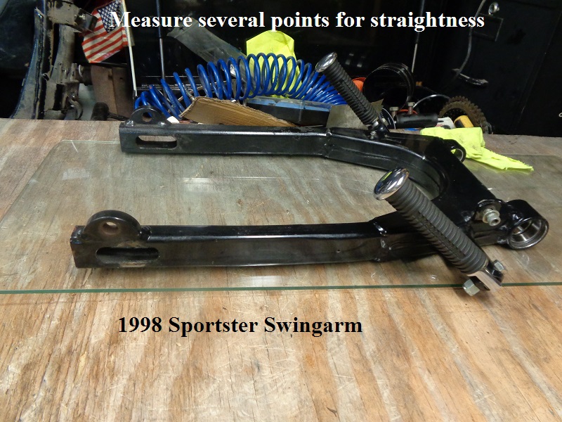
Check that the swingarm isn't warped, damaged or rusted.
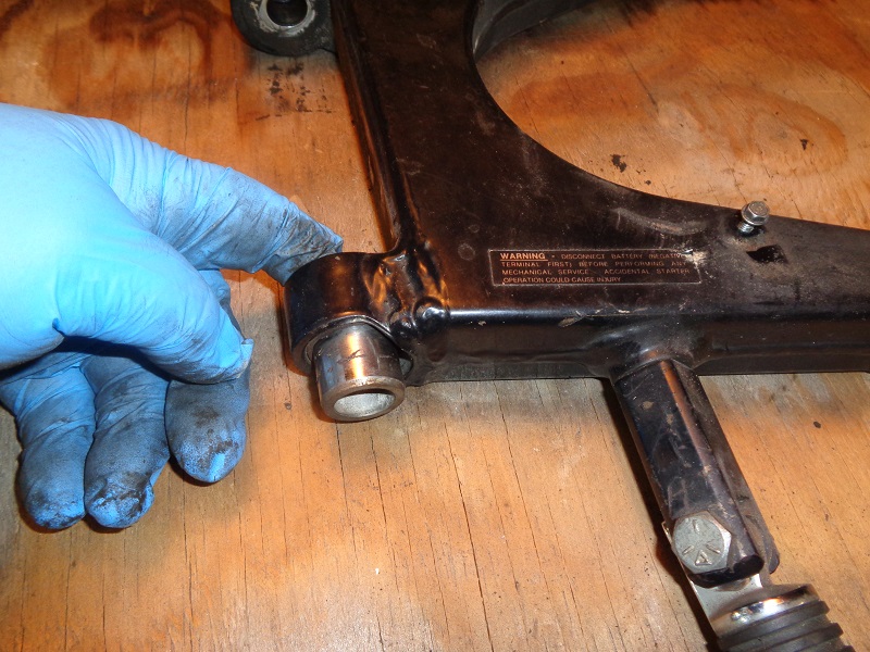
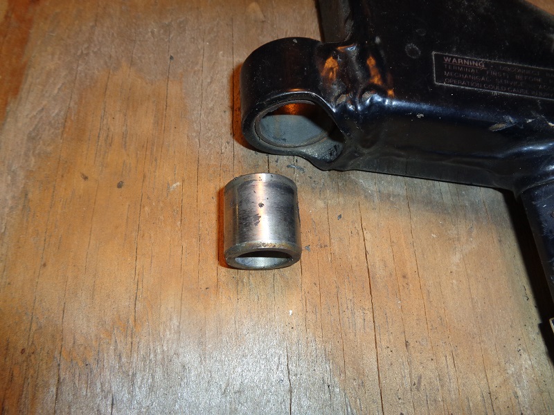
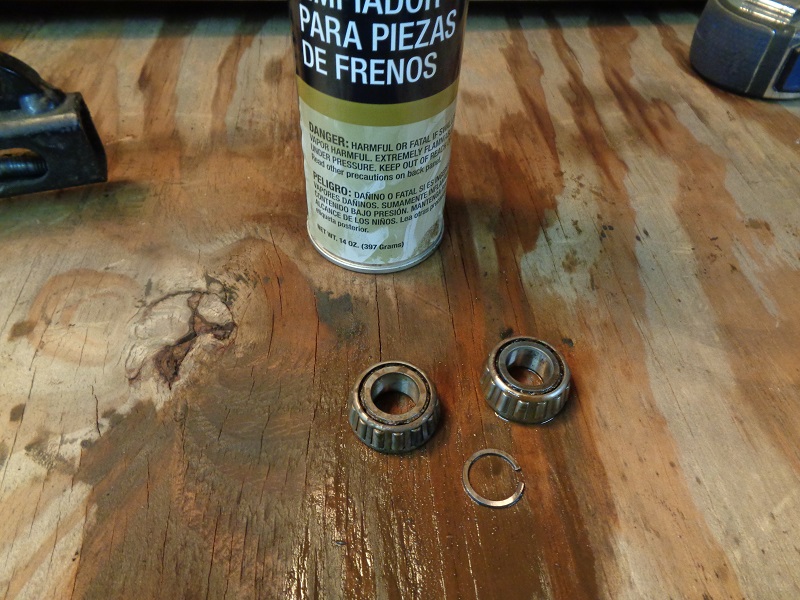
Remove the pivot bolt spacer and inspect both the spacer and it's bushing in the left pivot for damage or pitting.
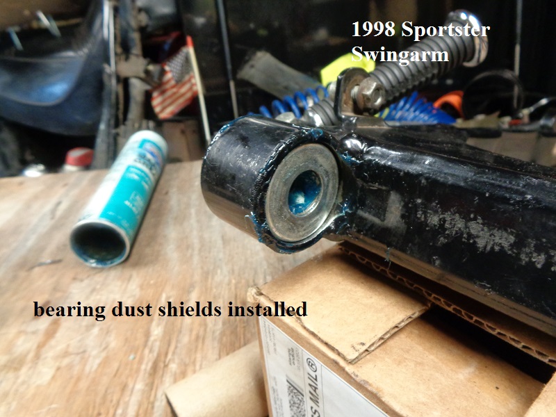
Remove the bearings from the right pivot.
You may be able to simply push a finger in the hole and wiggle the dust cover off or you can use a small pick to pull it out then remove the first bearing.
From there you just push the other bearing out through the pivot.
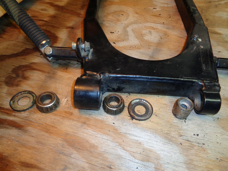
Hopefully your bearings won't look as bad as the ones below. You can spray them down with brake cleaner to clean off the old grease.
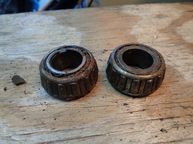
With extreme buildup, you can simply dunk them in a gallon of carb cleaner and let them soak for a couple hours and spray them down with water and re-lube them.
However you clean them, the old grease needs to be removed so it won't contaminate the new grease.
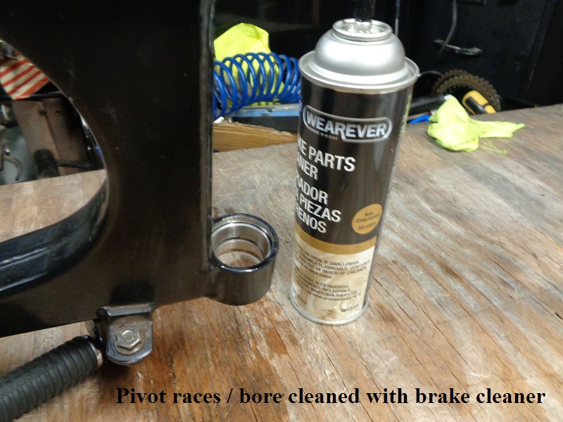
Clean both bearing races and inspect them for smoothness, pitting and out of roundness.
The races below are damaged and have to be replaced.


Bearing Outer Races
Removal


Installation
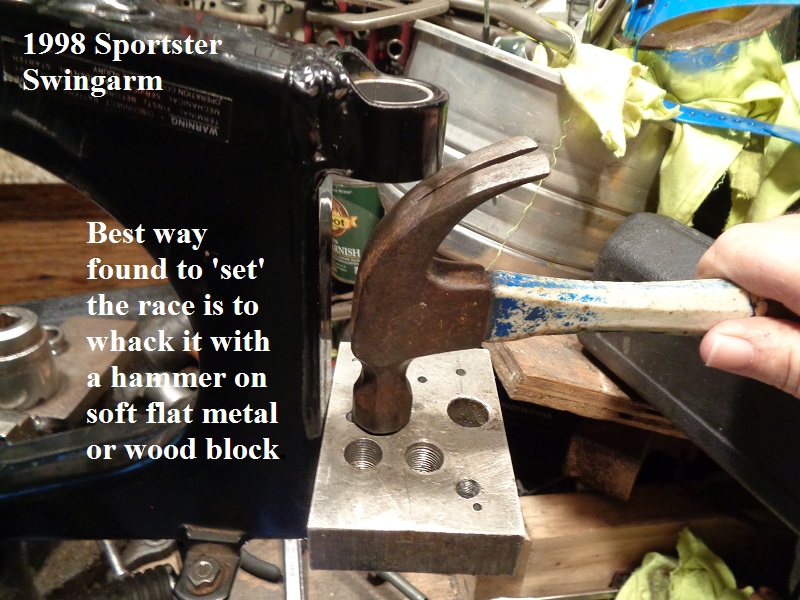
The race has to be installed straight in the bore. Getting it to go in straight can be very difficult however.
Tool list is a little hazy since several methods were tried to see what was most effective.
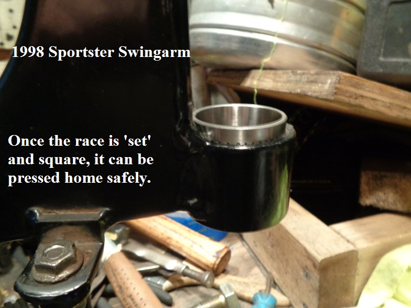
The best tools ended up being a flat aluminum scrap piece and a hammer to 'set' the races in straight and a threaded rod and socket press to pull the races home.
Just slight tapping was all that was required to get them started.


Pivot Spacer Bushing
Removal
The FSM says to replace this bushing only if needed.
However, there is no criteria / spec to determine if it's needed. Use your best judgment.
If it's really in bad shape, you'll know it when you see it.
Also, there is no clearance spec in the FSM for the spacer to bushing fit.
The bushing is pressed in and likewise will have to be pressed out. They make a special tool for removing / installing the bushing.
The rig below can also be used as a remover / installer tool.
- Parts:
- A length of 3/8“ threaded rod.
- (2)- 3/8” nuts and washers
- (2)- Sockets (you'll have to measure what you have on hand for proper fitment).
In this case, (1) 1-1/8“ and (1) 25/32” socket was used.- 1 has to either fit inside (outer races removed) or outside (outer races installed) of the right pivot.
The one used below was set against the bearing lockring in the middle of the right pivot.
Caution, do not use a socket on the inside if the races are installed. That could mar the internal bearing surface. - The other has to fit inside the right pivot and only a few thousandths (preferably) smaller than the bushing O.D.
Too small and it will mushroom the inside of the bushing.
Too big and it'll get stuck in the pivot.
Caution, measure to make sure it's smaller than the I.D. of the pivot before using it.
- (1) 1/2“ washer (optional).

Install the tool snug by hand and double check that the sockets are centered before tightening with a wrench.
Begin tightening and it will get hard to turn, then it'll eventually pop. It may sound like you just cracked the swingarm.
At any time, you can loosen / remove the tool and check the progress to make sure the socket isn't mushrooming the bushing instead of pushing it out.
It will probably be very tight will possible rust buildup and time.
But always keep in mind it may be tight because the socket got sideways and is now pulling against the pivot instead of the bushing. Double check if needed.
You can damage / crack the swingarm if this is not done properly.


It may 'pop' several times before it breaks free enough to pull out easy.
When this happens, pay attention to the bushing. You'll see it pull out more when you hear the pop.
Of course, the bushing may come out easily depending on what state it's in.
Just be aware of this so it doesn't surprise you. Keep turning the nut until the bushing slips out.
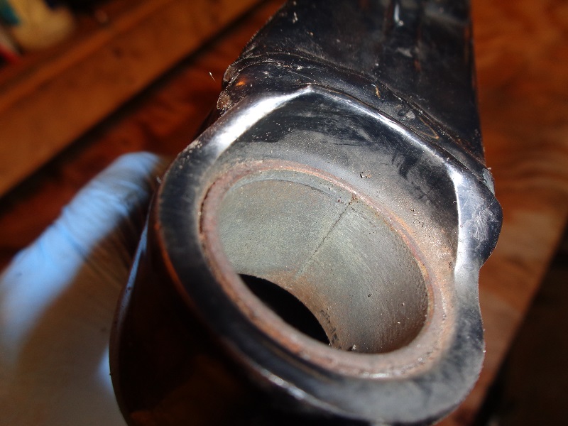
Then inspect the pivot bore for rust, pitting, cracks etc. Replace or repair the swingarm as needed.


Installation
Clean the pivot bore and the new bushing with solvent, acetone, brake cleaner etc.
It has to install dry with no grease in the bore on the bushing.

Install the bushing with the beveled end toward the bore. If both ends are beveled, it installs either way.
Line up the bushing square to the bore. The socket below had rounded edges which allowed it to kick sideways when torque was applied.
So a larger 1/2: washer was used to create the flat surface to initial pull in the bushing and keep it straight in the process.
Once you get the bushing snugged up by the tool, you can give that nut a sharp whack with a rubber hammer to 'set' the bushing face in the hole.
Then snug it back up, check for square and start pulling it in with the tool.


When you start tightening the tool, the nut will get hard to turn as the bushing gets squeezed into the bore.
But once it starts pulling in, the pressure should be consistent.
If the nut gets hard to turn all of a sudden, don't be afraid to remove the tool and check for obstructions and alignment.
Actually, a cheater bar was used on the wrench to pull the bushing in on the last 1/4” or so on this one.


Check to make sure the bushing wasn't damaged on installation.
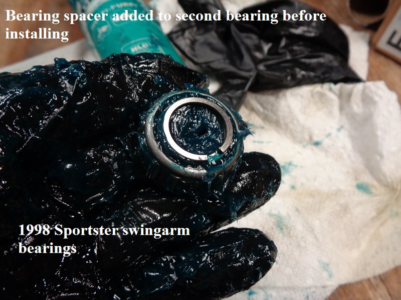
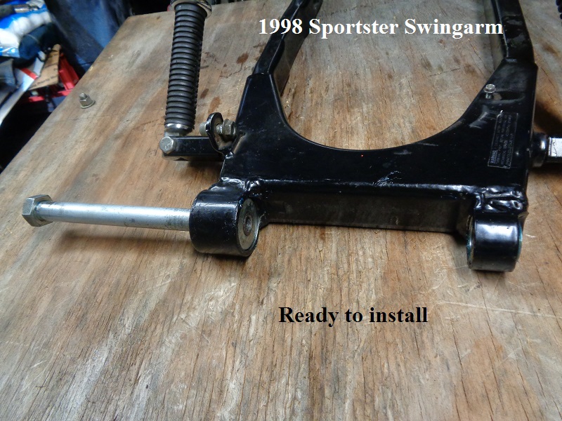
Install the pivot bolt spacer to make sure it glides freely without bumps or stops.
The spacer is a slip fit and should not bind during operation.


Removing the Bearing Lockring
Caution: Use eye protection as the lockring may pop out on you.
There is no reason to replace this ring unless it's damaged or rusted to the point it will hinder proper bearing race installation.
The races butt up against this ring on both sides and that determines distance apart from each other thus how far the inner bearing race sticks out the end.
So the races have to be installed correctly.
The ring can be used for both internal and external applications. However, the tool for these rings only works on external applications.
It pushes each end outward to expand the ring to remove it from shafts and the like.
There are no known pliers to compress the ring due to it having no holes or slots for pliers.
So it will need to be pried out with screwdrivers in a circle pattern to get the ring out of the groove in the pivot.
Once the ring is completely out of the groove, you can push it out of the pivot with a socket sized smaller than the pivot and near the same size as the ring.
Or it may just pop out on it's own. 17)


The ring needs to be installed with a tapered sleeve so you can set it in one side and knock it into the bore while the sleeve taper narrows the ID of the ring.
But without having that tool, a socket was bolted up into the bearing bore sitting on top of the open end of the ring to keep it from popping out.
Then the other side of the ring was carefully knocked into the bore with a wooden dowel and a hammer.
Once the ring was fully in the bore, the socket was used to know the ring down so it snapped into the groove. 18)


