Table of Contents

IH: Engine Control - Sub-01A
Battery Ignition (circuit breaker/timer)
57-78 Sportsters (except XLC and XLCH)
- The circuit breaker ignition system has two circuits; (1)-the primary and (2)-the secondary circuits. 1)
- The primary circuit includes the battery, switch, primary coil and the breaker points.
- The secondary circuit consists of the secondary coil and the spark plugs.
- The breaker cam and contact points open and close the low tension circuit between the battery and the ignition coil.
(which causes the coil to produce high voltage discharge to the spark plugs) - The circuit breaker also times the discharge for proper engine firing.
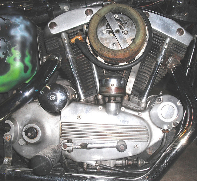
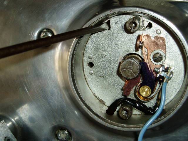
External Circuit Breaker (57-70)

- The circuit breaker ignition was not factory installed on XLCH engines.
- However, they provide consistent lighting for riding at night.
- The magneto has been changed out to a circuit breaker ignition on many XLCHs
| Circuit breaker ignition on a 70 model XLCH 4) |
 |
- You've got 2 sets of gears that turn the circuit breaker. 5)
- The pinion turning the cam gear.
- Then the cam gear turning the circuit breaker (distributor).
- Each gear set has to have a certain amount of looseness or backlash.
- Then the cam and the distributor shaft run in bushings (which can suffer wear.
- The cam also gets affected by the fact it's also opening and closing a valve.
- If you've got advance weights, they and the point cam can become sloppy.
- So there's a lot that can contribute to the timing jumping around.
Contact Points
Single Contact Points - Manual Advance
A single contact point circuit breaker is operated by a cam with a narrow lobe and a wide lobe. 6)
- The narrow lobe times the front cylinder.
- The wide lobe times the rear cylinder.
- A single ignition coil fires both spark plugs at the same time.
- One cylinder on compression stroke, firing the combustion gas creating the power stroke.
- The other cylinder through the exhaust stroke (wasted spark).
- The non-firing plug will run at the same temperature as the firing plug as long as they're all the same heat range. 7)
- If the firing plugs aren't building up carbon, the “spares” shouldn't either.
- A spark plug's running temperature/heat range isn't correlated to being connected to the coil.
- Timing is advanced or retarded by manually rotating the circuit breaker base in relation to the breaker cam.
 |  |
| Single Point Circuit Breaker on a 57 XL 8) | |
Single Contact Points - Auto Advance
The single set of points are operated the same way as the manual advance (by a cam with a narrow lobe and a wide lobe) with the addition flyweights.
(the spark timing cam is advanced automatically with engine speed) 9)
- The narrow lobe times the front cylinder.
- The wide lobe times the rear cylinder.
- A single ignition coil fires both spark plugs at the same time.
- One cylinder on compression stroke, firing the combustion gas creating the power stroke.
- The other cylinder through the exhaust stroke.
- Timing is advanced or retarded with an increase or decrease of engine speed by the action of the flyweights.
Dual Contact Points
Two independent sets of points are operated by separate cam lobes (each having it's own cam). 10)
- Each breaker cam opens the points individually which fires to the alternate cylinders with every revolution of the crankshaft
- Dual ignition coils (one for each spark plug) fire each cylinder independently.
- Timing is advanced or retarded by the breaking of each set of points by the single lobe cam on the timer shaft.
Setting / Adjusting Point Gap
Point gap should be set before ignition timing adjustments. Incorrect point gap spacing will affect timing. 11)
Single Contact Point Circuit Breaker. 12)
Point gap spacing should be exactly .020“ (measured with a feeler gauge) when the fiber cam follower is on the highest point of the cam.
- Loosen the points lock down screw and use the eccentric adjusting screw to move the point gap to the correct setting.
- Tighten the lock down screw and re-check the gap, repeat if it moved.
Dual Contact Point Circuit Breaker. 13)
Point gap spacing should be exactly .022” (measured with a feeler gauge) when the fiber cam follower is on the highest point of the cam.
Check ignition timing whenever dual points are adjusted.
Any change in the rear point gap affects timing.
- Front (marked with an “F”) and rear points are adjusted separately.
- Loosen the front lock down screw and use the eccentric adjusting screw to move the point gap to the correct setting.
- Tighten the lock down screw and re-check the gap, repeat if it moved.
- Then repeat the procedure for the rear points.
- Both point gaps should have the same gap spacing.
Setting /Adjusting Ignition Timing
Manual Advance Single Point Circuit Breaker
Auto Advance Single Point Circuit Breaker
Manual Advance Dual Point Circuit Breaker
Internal Circuit Breaker (71-78)
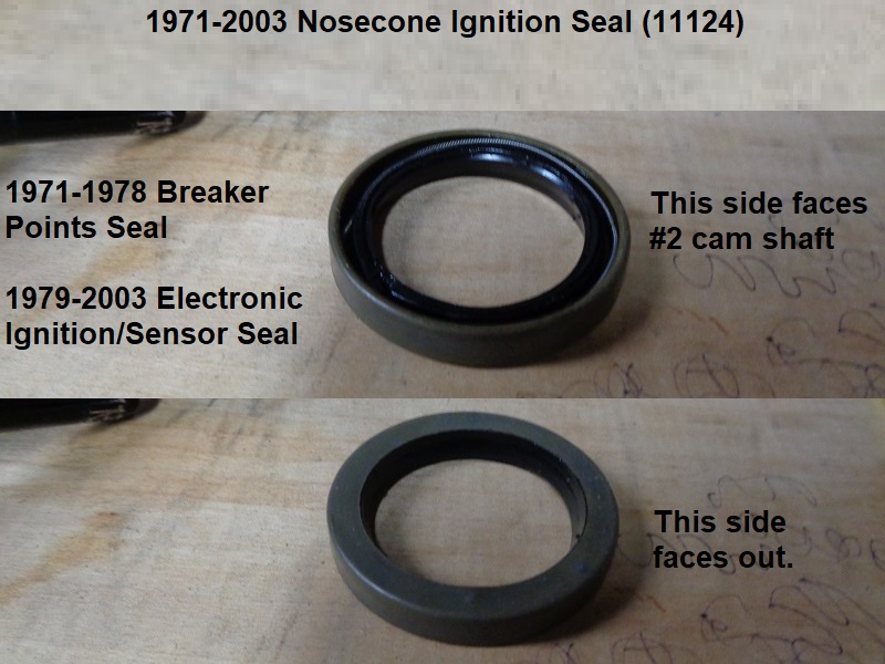
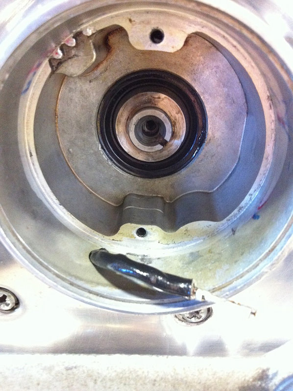
Breaker Points Seal
This is a steel shell radial shaft seal (HD# 11124) installed in the cam cover.
It surrounds and seals #2 cam when the cover is installed. Also used on 1986-2003 model Sportster cam covers.
Dims per XLForum member, Fizzle:
OD 1.570“ (39.878mm)
ID 1.050” (26.67mm)
W 0.248“ (6.2992mm)
Other brands include James (JGI-11124), Cometic (C9355), Athena (51-A210), Custom Chrome (54-043).
The rubber shell HD Genuine double lip version is part number (11124-DL).
Other brands include James (JGI-11124-DL).
NOTE: SKF makes a radial shaft seal with a part number of 11124 but that IS NOT AN HD PART NUMBER.
SKF 11124 IS TOO BIG TO FIT THE COVER and they don't show a compatible seal in their catalog for this application.
HD Seal (11124):
Roll Pin
AKA “split pins”. These are hollow pins that have a split in them and are held in holes by their own spring tension. 15)
It is possible to have it 180° out by mashing down the pin while tightening everything up. 16)
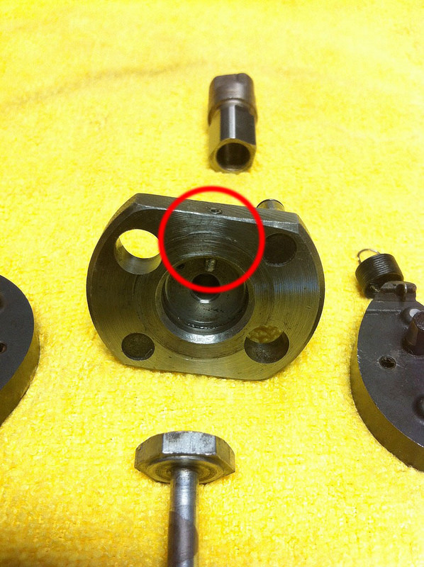
It's also common for the breaker cam pin to be sheared off flush with the base and covered in grime so you can't tell the correct orientation for the cam.
It'll install both ways like this, but only one position will fire the plugs correctly. 17)
If the first roll pin is pushed too deep, it can cause problems with getting both gaps even.
It will cock the advanced unit and not let it seat flush on the cam. 18)
If the bike will backfire, spit and cough very badly with the cam plate adjusted,
Check for missing, bent or destroyed roll pins on the plate. 19)
| The 1st roll pin is on the top side of timing plate assembly. 20) | The 2nd roll pin is on the back side of the timing plate assembly. 21) | During installation, the back side roll pin aligns with the notch in the #2 cam 22) |
 |  |  |
Ignition Timing
Setting Ignition Timing with a Cigarette Paper
Also, see this video on setting the timing 23)
This can be done without a strobe light or a multi-meter. 24)
This is the old fashioned way of timing a points equipped Harley (providing the ignition system and cam gears are in good condition).
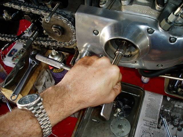
- Pull the spark plugs out to make turning the engine over easier.
- Remove the bolt holding the condenser and move the condenser out of the way.
(The wrench will not get in to turn the cam with it in place)
Setting Points Gap
- Set the points gap with a set of clean feeler gauges.
- Standard setting is .018”, with a .020“ max and a .016” min.
- To set the points gap, loosen off that pesky bolt in the middle of the points cam VERY CAREFULLY.
Nudge the cam while tightening that bolt, VERY CAREFULLY.
That big bolt head is on a skinny 3/16: bolt shank and should be tightened to just more than finger tight with no Loctite needed on it. - The points open the widest just as they are initially opening.
If you keep turning the engine to the middle of the lobe, they close up a couple of thousandths.
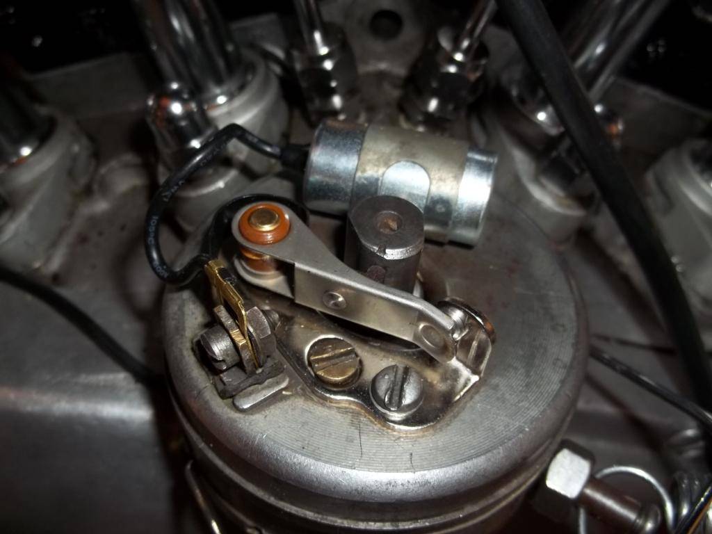
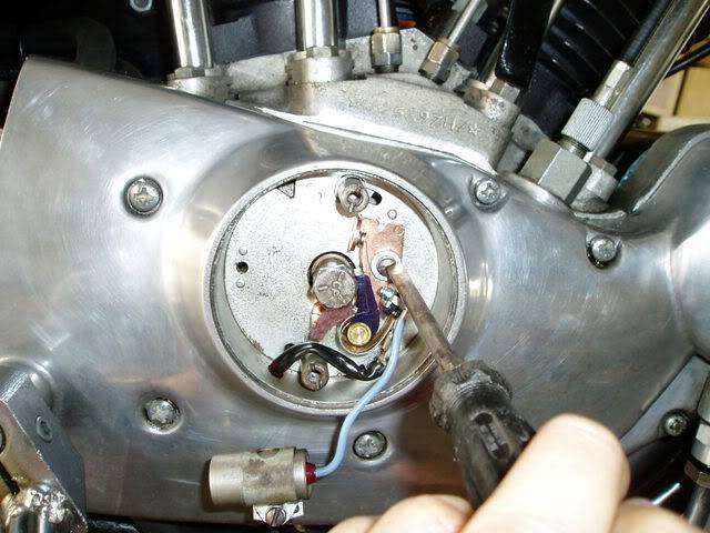
| This is the locking screw for adjusting the points gap. Note, leave the condenser hanging out for room to do the timing, later. 25) | This is the notch to lever the points adjustment to open or close the gap. 26) | Holding a 3/8“ socket drive like this won't allow you to get too much leverage and break that skinny bolt. 27) |
 |  |  |
Timing Adjustment
- First, set the front cylinder on the compression stroke.
You can watch for both front push rods to become bottomed out 28) (collapse the push rod tubes to see the push rod action)
See also Using the finger method to find the compression stroke and Using a TDC Whistle to find the compression stroke. - Next, remove timing hole plug from the left crankcase.
Put the front cylinder advance timing mark in the center of the hole while still on the compression stroke. - This sets the front piston at 40° before Top Dead Center (TDC) on the compression stroke.
(where the spark occurs when the engine is revving at high revs, with the auto advance unit at full advance).
| Front flywheel timing mark in inspection window. Front cylinder on compression stroke. 29) | Rear flywheel timing mark in inspection window. Rear cylinder on compression stroke. 30) |
 | 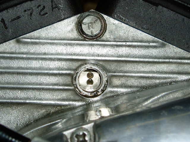 |
- Then leaving the engine in that position with the flywheel line in the middle of the inspection hole, go back around to the points.
- Now, it is time to get out the cigarette paper and do the circuit breaker points static timing.
- Tear the cigarette paper in half lengthways and insert it between the points. They will need nudging open with your finger to get the paper in there.
- The object is to position the points so that they are just opening at the full advance position.
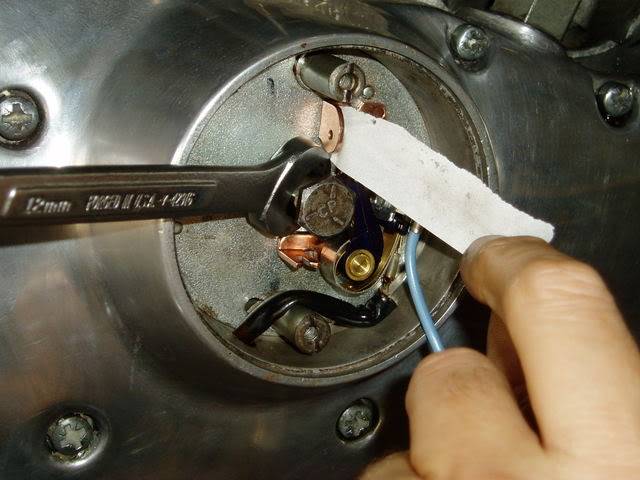
Pull gently on the paper, which is held firm by the points. - You can use a 12mm wrench, or pliers, and turn the points cam counter-clockwise.
- When you feel the points cam hit the end of its movement, the cigarette paper should just come lose and start to slide, with a bit of drag, out of the points.
- If it sticks there, or slips out before the points cam reaches the full advance position and stops, adjust the points backing plate to move the points to the right position.
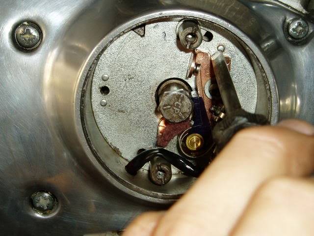
| Cigarette paper in place, spanner to turn points cam to full advance. 31) | This screw, and the one at the top, anchor the backing plate and must be loosend to adjust timing. 32) | Then, lever the whole backing plate a fraction back or forth using this notch for your screwdriver and then tighten up the locking screws when your done. 33) |
 | 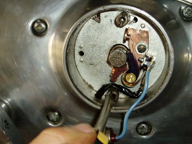 |  |
- It might take a few tries to get it.
(so the paper pulls loose as the points cam hits the full advance stop and the timing mark is in the middle of the window). - Then, check the points gap again and if it is too far out, repeat the whole process until it's right.
- Then, bolt the condenser in back into position.
- When the timing is done for the front cylinder, the rear cylinder timing should also be spot on.
- However, with worn or mismatched parts, this might not be the case.
- This process can be repeated for the rear cylinder (on compression stroke).
Troubleshooting
- If your advance cam will not move, you need to take a look at the advance unit in behind the point plate. 34)
- It may be damaged or froze up.
- Point gap should be the same between the large and small cam lobes. 35)
- If point gap exceeds .004” between them, the cam lobe is running eccentric and it should be corrected.
- Loosen the center bolt and reposition the advance weight assembly toward the widest point gap to equalize the gap. 36)
Auto Advance / Breaker Weight Springs
- Starting on January 3, 1969, the MoCo changed the size of the wire of the two ignition timer weight springs on Electra Glide and Sportster models to increase the speed at which timing advance occurred. This was to insure that the spark timing would be fully retarded at cranking speed and will advance gradually as RPMs increase to the fully advanced position. 37)
- Auto advance 1st appeared on the 1965 XLH. It was also used on the 1966 XLH also. 38)
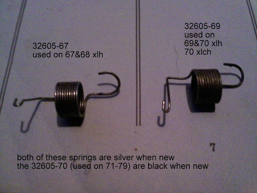
- The black -70 springs in these timers don't seem to work nearly as good as when using either -67 or -69. 43)
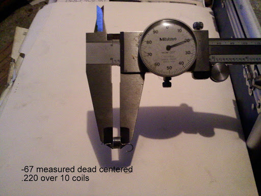
| 1967-1968 XLH | 32605-67 using (0.022“ wire) - fully advanced at 1600 RPM 44) |
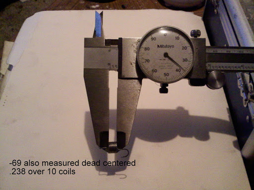
| 1969-1970 XLH 1970 XLCH | 32605-69 using (0.016” wire) - fully advanced at 900 RPM 45) |
| 1971-1979 XLH / XLCH | 32605-70 46) |
- Before checking ignition timing, remove the circuit breaker plate nuts and plate cover to make sure the flyweights will move freely. The cam must return back to retarded position when the engine is stopped. If it doesn't retard fully, it usually causes failure of the starter drive. 49)
- Also, on 1967 and later models, make sure that the bent end of the flyweight spring is hooked through the bottom hole and the upper loop grips the retaining groove in the pin tightly. 50)
- Replace the breaker plate cover and set the point gap at 0.020“ before checking / setting the advance timing. 51)
Circuit Breaker Cam
The circuit breaker cam, or ignition timer cam, (newly designed for the 1971 model year) was redesigned for the 1972 model year and was recommended as a replacement for parts order on 1971 model Sportster, Electra Glide and Super Glide models. The 1971 (32542-70) cam had a more rounder profile while the 1972 cam (32542-70A) was more radical with sharper corners at the sides with a flat or straight edge ascend to the cam top center from each side. The 1972 cam allowed greater range in point gap adjustment making (the adjustment less critical) and timing more consistent from cylinder to cylinder. Point gap specs remained the same between the two cams but the dwell changed from 90° to 140° with the '72 cam.
| Ignition Timer Cam | ||
| 1965-1970 | XLH | 32542-64A |
| 1970 | XLCH | 32542-64A |
| 1971 | XLH/XLCH | 32542-70 (original) |
| 1971-1978 | XLH/XLCH | 32542-70A (new design) |