Table of Contents
This is an old revision of the document!

IH: Engine Mechanicals
See also Crankshaft / Flywheel Tools in the Reference section of the Sportsterpedia.
Sub-Documents
Gearcase / Cam Cover
| Cam Cover (casting 25202-52A) 1) |
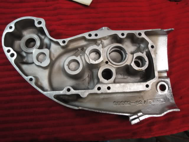 |
Cam Cover Bushings
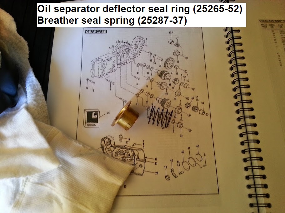
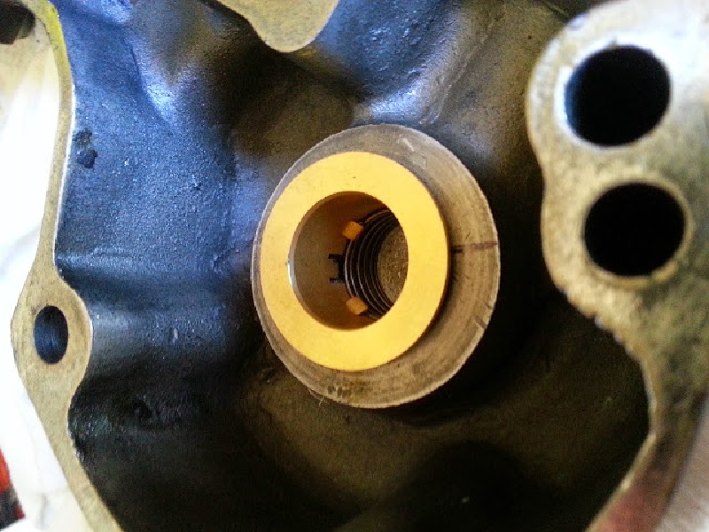
Oil Deflector / Separator Bushing Assembly (57-62): (or spring loaded top hat)
Looking at the brass part, you can see how the spring catches on the inward bent tabs. There are also unbent tabs on the brass. 2)
These, when bent outward just a little, fit into slots on the far side of the steel bushing pressed into cam cover.
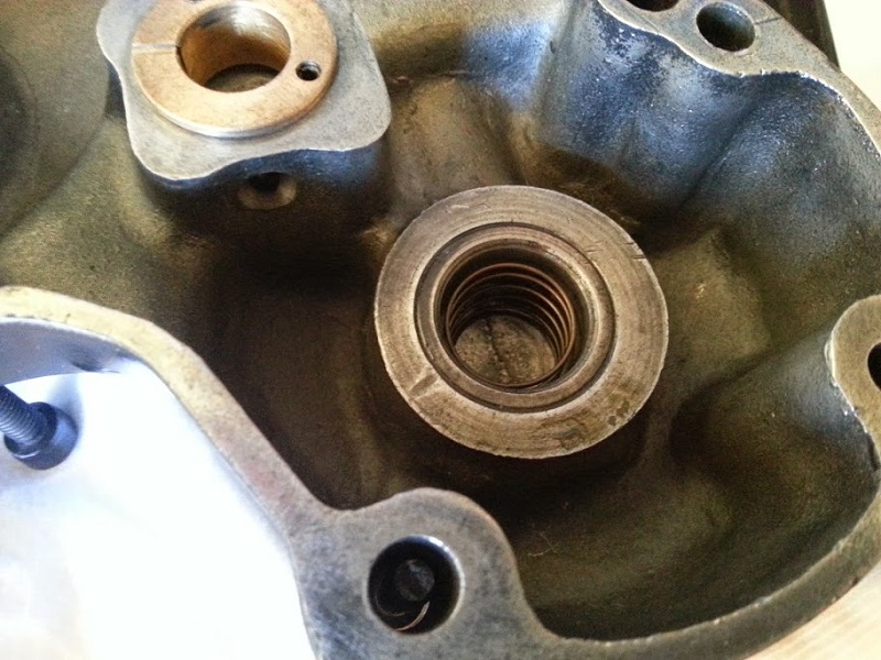
Here's how the factory assembled this thing.
They had pre-assembled the brass to the steel before the steel was pressed into the cover.
Then dropped the spring into the cover and pressed the brass/steel assembly into the cover as a unit (and manipulated the spring to sit correctly if needed).
However, it is possible to assemble the unit without removing the steel from the cover. 3)
You can bend the tangs out without having to remove the steel bush with a screwdriver and a hammer to bend the 2 locating tabs out.
Notes:
The tabs must be bent outward enough that the brass stays keyed to the steel at full spring compression.
You don't want the brass hat to 'unkey' when the generator compresses spring.
The brass needs to be able to 'plunge' in and out under the spring pressure once the tags are bent.
If you get too aggressive, you can cause deformations in the brass that allow it to hang up in it's sliding fit to the steel.
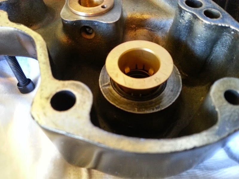
These outward bent tangs do 2 things.
- They keep the brass hat and spring captive in the cover upon generator removal.
- More importantly, they key the brass to the steel to prevent the brass from rotating with the generator gear.
The brass is unable to rotate by the tangs keying into the slots.
Inspection:
Check the operation of the oil separator bushing assembly.
The spring should have free action and be fully extended in the gearcase cover.

Flywheel
Sub-Documents
Commonized Flywheels
- In May of 1981, the MoCo issued a bulletin stating that product and quality improvements have brought about a commonized flywheel taper design.
All tapers were communized at 6° and all keyways were standardized.
In June of 1981, an update to this bulletin was issued to include part numbers. 9) 10)
- A limited number of E1982 XL engines (782216009-782237017) were assembled without the communized flywheel taper design. 11)
- Notable component changes are included in the chart below.
- This was a running change in 1340cc and 1000cc engines but both new and old designs were used in production until the old stock parts ran out.
- Even though the assembly and disassembly was the same for the old and new style flywheels, the torque values did change for the new style assembly. However, new and old style components must not be intermixed.
Changes for Sportster 1000 engines include:
| New Flywheel - Sprocket Side Gear Side | 23916-80 23936-80 | 'Lazy 8' rear cylinder timing mark and no keyway Single hole oil path. |
| The old style flywheel has a keyway on the sprocket side (23916-57A) and a compound (2) hole oil path on the gear side (23936-57A). | ||
| New Crankpin | 23960-80 | Oil hole is now 90° to the keyway |
| Old style crankpin (23960-54) oil hole was 110° to the keyway | ||
| New Crankpin Nuts | 23901-81 | 20/1“ thread pattern at 150-185 ft/lbs. |
| Old style crankpin nuts (23967-54A) were 20/1” threads with 150-175 ft/lbs. | ||
| New Sprocket Shaft | 24000-80 | No keyway |
| Old style sprocket shaft (24000-75) has a large keyway | ||
| New Sprocket Shaft Nut | 23902-81 | 3/4“ x 20 threads at 100-120 ft/lbs. |
| Old style sprocket shaft nut (8011) has 11/16” x 18 threads at 100-120 ft/lbs. | ||
| New Sprocket Shaft Key | Not used | |
| Old style sprocket shaft key (23985-12) has a large woodruff key (3/16“ x 1/2”) | ||
| New Gear Shaft | 24005-80 | One piece construction |
| Old style gear shaft (24008-75A) is of two piece construction | ||
| New Gear Shaft Nut | 23902-81 | 3/4“ x 20 threads at 100-120 ft/lbs. |
| Old style gear shaft nut (8011) has 11/16” x 18 threads at 100-120 ft/lbs. | ||
| New Gear Shaft Key | 11218 | Small woodruff key (1/8“ x 3/8”) |
| Old style gear shaft key (11200) has a large woodruff key (3/16“ x 1/2”) | ||
| New Crank Key | 11218 | Small woodruff key (1/8“ x 3/8”) |
| Old style crank key (23985-18) has a large woodruff key (1/8“ x 1/2”) | ||
Roller Bearing Inspection (1957-1976)
- In a letter dated May 9, 1977, an HD interoffice memo was sent regarding an inspection of parts stock roller bearings. Some roller bearing part numbers were found to have incorrect diameters. A new micrometer was purchased to remedy this problem.
- Two of those part numbers are gear shaft (9421) and crank pin front rollers (9150A) for Sportsters.
- In light of this oversight, a listing of part numbers with their correct dims and tolerances was issued as in below:
| Used for 57-76 Sportster gear shaft roller bearings | Diameter | Size | Length |
|---|---|---|---|
| 9421 | .1876“ - 1974” | Standard | .800“ - .796” |
| 9422 | .1878“ - 1876” | + .0002“ | .800” - .796“ |
| 9423 | .1880” - .1878“ | + .0004” | .800“ - .796 |
| 9424 | .1882” - .1880“ | + .0006” | .800“ - .796” |
| 9425 | .1884“ - .1882” | + .0008“ | .800” - .796“ |
| 9426 | .1886” - .1884“ | + .0010” | .800“ - .796” |
| Used for 54-85 Sportster and K Model front crankpin roller bearings | Diameter | Size | |
| 9150A | .1875“ - .1874” | Standard | .480“ |
| 9152A | .1877” - .1976“ | + .0002” | .480“ |
| 9154A | .1879” - .1878“ | + .0004” | .480“ |
| 9156A | .1881” - .1880“ | + .0006” | .480“ |
| 9158A | .1883” - .1882“ | + .0008” | .480“ |
| 9160A | .1885” - .1884“ | + .0010” | .480“ |
| 9161 | .1873” - .1872“ | - .0002” | .480“ |
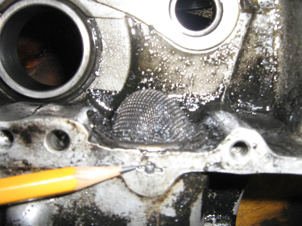
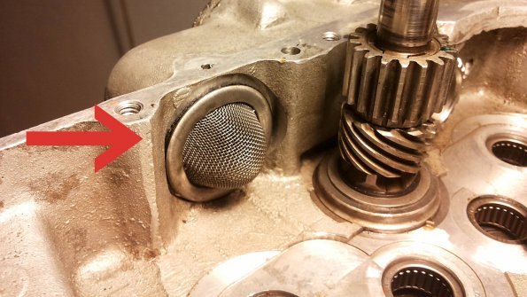
Crankcase Oil Strainer
- If you've split the cases and the screen is in good shape, you don't have to take it out. Hit it with some compressed air and see if it needs replacing. 12)
 13)
13)  14)
14)
The strainer is held in place by this pin. It is staked into place with the two horizontal lines radiating from the it. To remove strainer, you must first remove the pin. Tear the screen from the strainer and place pliers on the pin inside (the now destroyed strainer) and wiggle the pin out. Strainers and strainer gaskets are available for replacement. 15)