Table of Contents
This is an old revision of the document!

IH: Engine Mechanicals
Crankcase Ventilation
See also in the REF section of the Sportsterpedia:
- Breather Valves (1957-Up) (list of breather valve changes)
Timed Breather Valve (57-76)
Sub Documents
57-76 engines breath and scavenge oil from the same oil galley in the rear of the sump.
The shallow sump, timed breather system, comes from the aviation world of old. 1)
Piston driven aircraft had to be able to evacuate the oil from the crankcase regardless of engine altitude and that system does that.
At the time Harley adapted that system they were copying the highest engine technology of the day.
They just took too long to abandon it as technology advanced.
Documents from HD Racing from the period show no HP gain between the 2 ironhead systems when the breather is properly timed ( which didn't happen a lot).
The rotary breather valve is integrated with the oil pump. The gear on top of the valve also operates the oil pump.
The breather valve connects the flywheel area to the gearcase.
The rotary breather valve functions to relieve pressure in the crankcase caused by the downstroke of the pistons and it controls the flow of oil in the lubrication system.
It is timed to engine rotation and opens on the downstroke of the pistons. 2)
This allows crankcase exhaust air pressure to expel the scavenge oil from the crankcase breather oil trap into the gearcase.
The breather valve then closes on piston upstroke, creating vacuum in the crankcase.
Crankcase exhaust air from the gearcase is sent out the breather tube.
Any oil still in suspension with the air on the way to the breather tube is separated by an oil slinger on the generator drive gear.
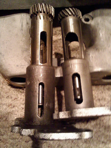
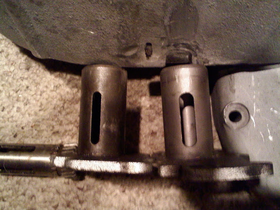
| Left is the unmodified 1/4 speed R valve. Right is the 1000 stock. | R model is the left one. |
 |  |
1956-1959 Breather Valve
- Breather timing and duration:
- Opens 25° (ATDC) and Closes at (BDC). 3)
- Duration - 155°
- 180° of vacuum from front (BDC) to front (TDC).
1960-1971 Breather Valve
1972-1976 Breather Valve
- Breather timing and duration:
- Opens 20°-25° (ATDC) and closes 85°-90° (ABDC). 6)
- Duration - 245°.
* Slot widths: 7)
- Slot in pump body: .345“
- Slot in pump gear: .625”
- 90° of vacuum from 90° (ABDC) to front (TDC).
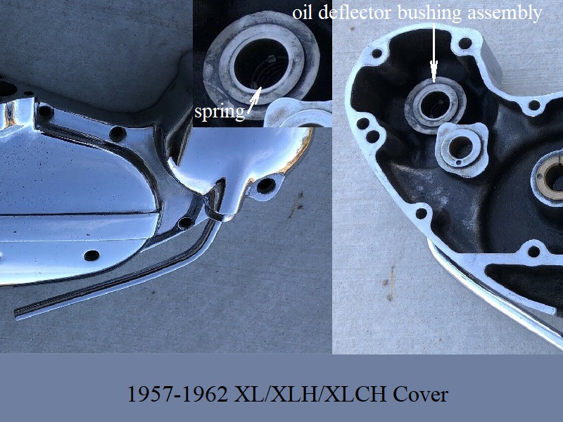
Oil Deflector / Separator Bushing Assembly (1952-1962)
AKA, (spring loaded top hat)
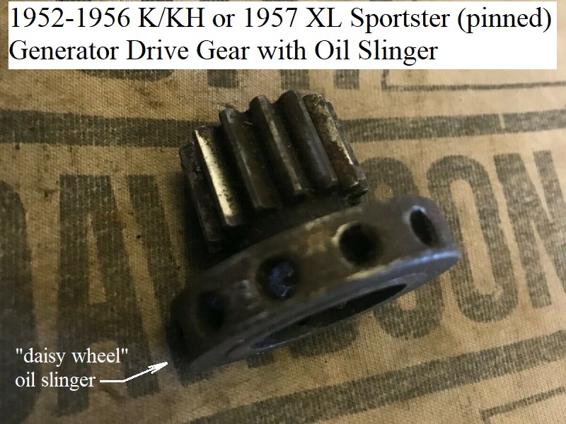
1952-1962 K Models and Sportsters used a drive gear on the generator with an integral oil slinger (daisy wheel) on the end.
Oil gets slung back into the gearcase and air is sent thru the oil deflector bushing and out the cover by way of the breather tube.
See more on the generator gear at the bottom of this page.
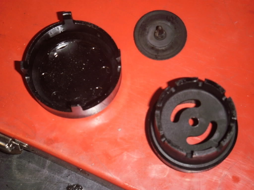
The oil deflector bushing consists of 2 pieces with the second being a brass oil seal insert “top hat”.
A spring (25287-37) sits under the top hat in the bushing bore.
The assembly is pressed into the front of the cover with the brass being spring loaded against the generator “daisy cutter” gear.
The brass part is an oil seal and the daisy cutter separates air from oil sending the air into the deflector bushing then out the breather tube.
The brass top hat has a spring under pushing toward the generator and the top hat has limited action keeping it inside the bushing.
Looking at the brass part, you can see how the spring catches on the inward bent tabs. 8)
The brass stays keyed to the steel at full spring compression and “plunges” in and out under the spring pressure.
The outward bent tangs do 2 things.
- They keep the brass hat and spring captive in the cover upon generator removal.
- More importantly, they key the brass to the steel to prevent the brass from rotating with the generator gear.
The brass is unable to rotate by the tangs keying into the slots.
From 1952-1963, the bushing/oil seal assembly was sold as a unit with both pieces being sold under part# (25265-52).
In 1964, the bushing was still sold under part# (25265-52) and the oil seal “top hat” was sold separately under part# (25270-52).
Inspection:
Check the operation of the oil separator bushing assembly.
The spring should have free action and be fully extended in the gearcase cover.

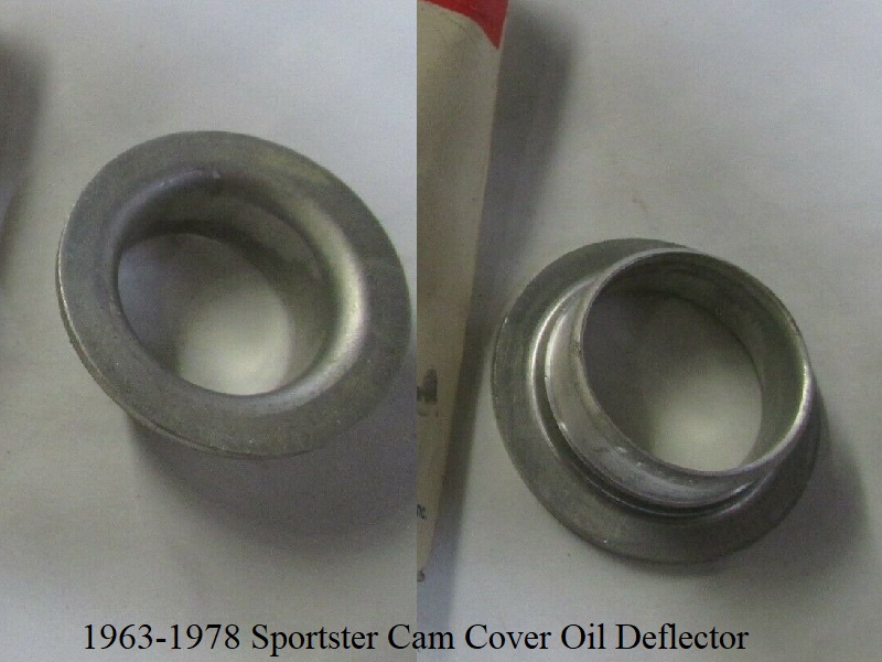
Oil Separator Deflector (1963-1978)
One Way Breather Valve (77-85)
The one way breather style system is more like a car PCV system. 12) Unlike an auto PCV, a Sportster has a faster acting type one way valve.
A deep (dry) sump was added to 77> casings and the scavenge side of the oil pump pulls the oil from the scavenge port in the rear of the sump area.
Holes were added between the crankcase and the gearcase wall (much the way your car's crankcase is vented out the top thru the valve covers)
Those holes in the walls are an open passage for crankcase pressure into the gearcase.
So the gearcase is also pressurized. Crankcase pressure is sent thru the one way valve in the cover and then vented to atmosphere out the vent.
So, 77-up engines breath and scavenge oil from separate places.
However, crankcase ventilation works a little differently on these motors than a Chevy. 13)
What you see on cars is an inlet, generally coming from the air filter, into the motor. Then an outlet, regulated by a PCV valve, going into the intake manifold.
So it's designed to flow a little air through the system.
The other thing is that a V8 crankcase stays at a constant volume, because for every piston going up there's a piston going down.
On a Sportster motor there's no air inlet. The engine vents into the intake flow on the upstream side of the carb instead, where there's much less vacuum.
It's not designed to flow air through it. What's more, the crankcase volume is constantly changing. There are check valves in line with the breather outlets.
Their function is to expel the air when the pistons go down but then restrict the air from entering the motor when the pistons go up.
The result is that beyond the first revolution, if the check valves are working properly, all you see out the breathers is the pulsating pressured air.
On a good motor, it's very little. But if the check valves are not working properly, the motor goes into an inhale/exhale mode.
That causes a whole lot air movement and it also causes a lot of oil to get carried out at the same time.
Many cases of excess breather oil is caused by poorly functioning check valves.
A mixture of crankcase air and oil mist is produced on each piston down stroke.
This forced mixture helps to splash lube the moving parts in the engine.
It also creates unwanted pressure in the engine. The oil mist is then separated from the crankcase air and the excess air pressure is vented out of the engine.
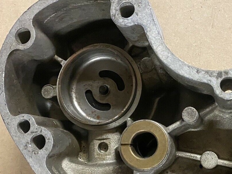
77-85 engines vent through a valve in the cam cover.
There were several changes made of the valve itself, but they operate on the same principle., a one way breather valve.
Where 76< engine crankcase volume is the simply the crankcase itself, 77> engines have the added volume of the gearcase as well.
With the non-timed breather valve closing at BDC, the bottom end volume has 180° of vacuum starting from front (BDC) to front (TDC).
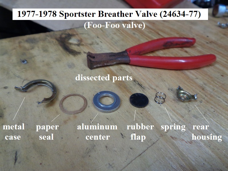
1977-1978 Breather Valve
See also Dissecting the 77-78 Breather (foo-foo) Valve (24634-77) for disassembly pics of the valve itself.
WHAT IS IT?
- The complete assembly is part# (24633-77). The valve itself is (24634-77).
- Thread size at cam cover is 5/8“-11. 14)
- The slang term “FooFoo” comes from the annoying sound that it makes when it gets clogged up with oil residue. 15)
- The engine breather (or crankcase vent) is to allow air out of the lower crankcase, but not in, as the pistons rise and fall. 16)
Without some kind of controlled breather, the lower end would become a 1,000cc air compressor, robbing the engine of several horsepower.
Old time tuners like Jerry Branch, Tom Sifton and Dick O’Brien paid much attention to the engine breather.
They knew it could give them extra horsepower if set up right. - One thing not to do with an engine breather is to simply plumb a hose to the crankcase without some kind of one-way valve or timed breather valve.
It is commonly done, but it wastes power and is not good for your engine.
WHERE IS IT? 17)
-
- The timed breather on the oil pump drive was dropped.
A new design breather valve (24633-77) was used in late 1977 model XL/XLCH/XLT engines produced around October 15, 1976.
All 1000cc engine numbers (3A, 4A or 2G) 27940H7 and above had the new breather valve.
It serves the same function as the gear driven breather valve used on 1976 and earlier engines to maintain a partial vacuum in the engine and prevent oil leakage.
Due to it's improvements in doing so, it was suggested to be retrofitted to all 1977 XL & XLCH engines. - The one-way valve is contained in a fitting which screws into the gear-case cover below the generator mounting boss.
The existing breather outlet pipe screws into the bottom of the new fitting.
The outlet pipe, because of its lower position, must be directed outside (instead of inside) the frame tube.
The rubber hose at the pipe outlet must no longer be used. - Because of the higher vacuum existing in the engines equipped with this new breather valve, a higher pressure oil pump check valve (26435-76A) was installed in L1977 oil pumps at the same time to provide higher oil pressure at the oil pressure light switch.
- The new valve opens at 4-6 PSI whereas the old valve opens at 2-4 PSI.
Pumps having the new valve are identified with a green dot.
The existing 0-ring (26433- 77) was used for both new and old valves. - An external non-return valve was plumbed into the vent tube sticking down from the timing cover at the generator drive.
This allows air out, but not in. It is sometimes referred to as the foo-foo valve.
Searching the XLFORUM for foo foo valve or foo-foo will lead to extensive discussions of this mystical device.
- Replacement options:
- It's a possible option for the 77-78 foofoo valve to be replaced with an external breather valve.
If you want to go this route, remove the internal valve as it will also change crankcase pressure with 2 valves in line.
Then, you might want to consider installing something like the external Krankvent or others.
Click here to see the Converting Head Breathers to Cam Chest Breather page in the Sportsterpedia.
That page is for an Evo conversion to cam chest breathing but the Krankvent and plumbing is shown.
You can also review this page in the Sportsterpedia Breather Venting / Relocation (especially the sub documents at the top of the page)
| 77 Cam Cover Breather Compartment. 20) | See “Dissecting the 77-78 Breather (foo-foo) Valve (24634-77)” for more pics and dims. 21) | |
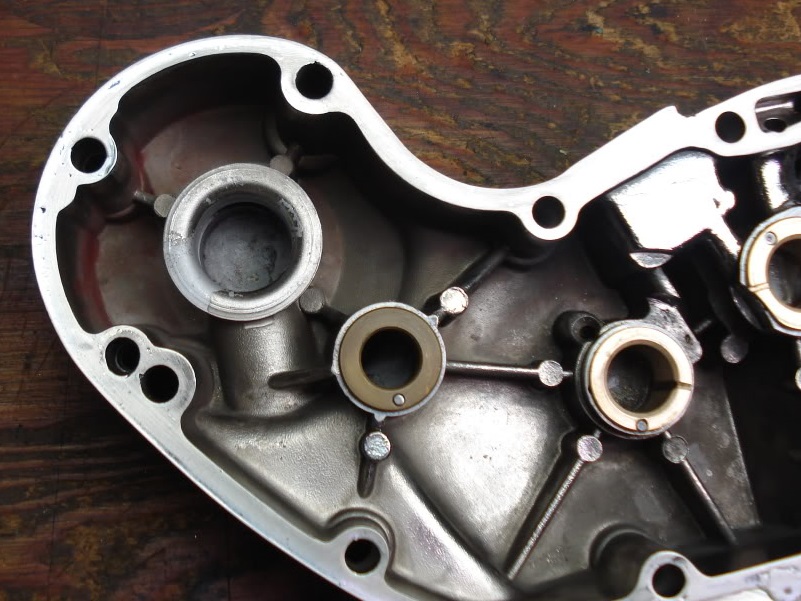 | 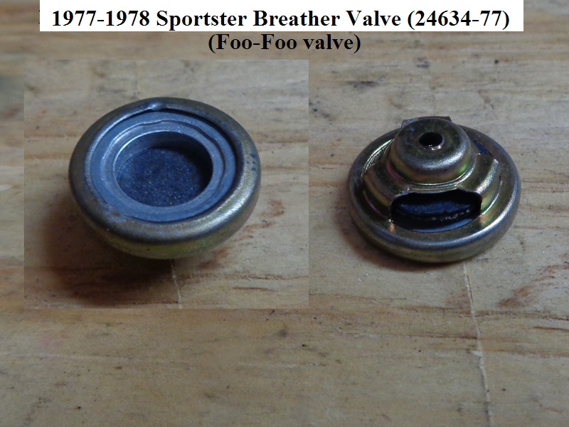 |  |
| 77-78 Crankcase Breather Valve 22) | ||
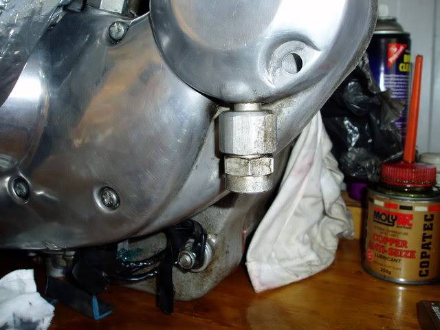 | 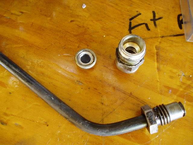 | 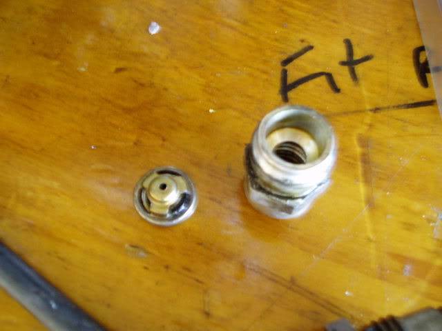 |
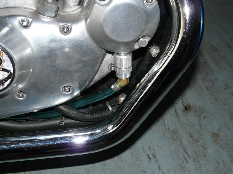
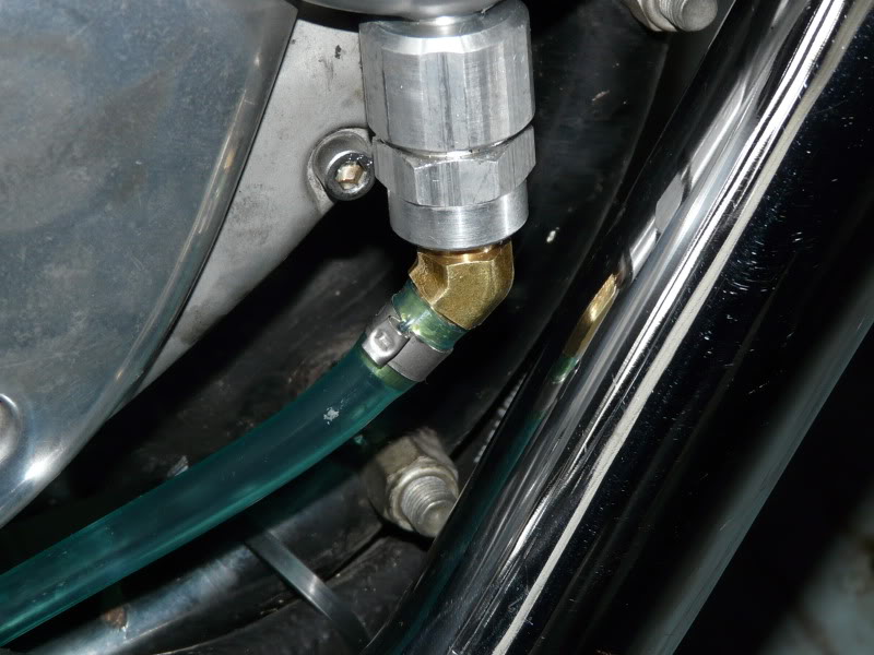
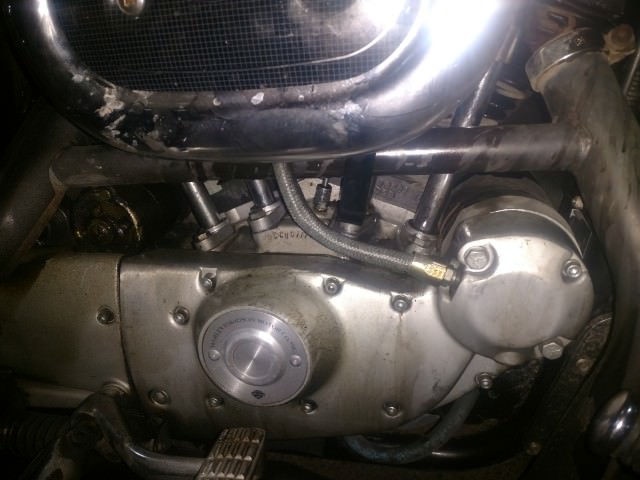
- This vent line mod was done due to problems fitting the stock tube as it hit the exhaust pipes.
- Thread size for the breather fitting is 5/8”-11.
- A piece of aluminum threaded rod, cut a small length to thread into the breather and drill / tap the hole for an 1/8“ pipe thread.
- A 45 ° hose barb fitting was installed to connect a length of hose that leads back along the frame.
This way the oil mist gets directed out back and doesn't collect along the frame and engine.
| Stock tube removed, fitted with 1/8” 45 deg barb fitting. 23) | |
 |  |
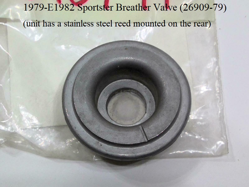
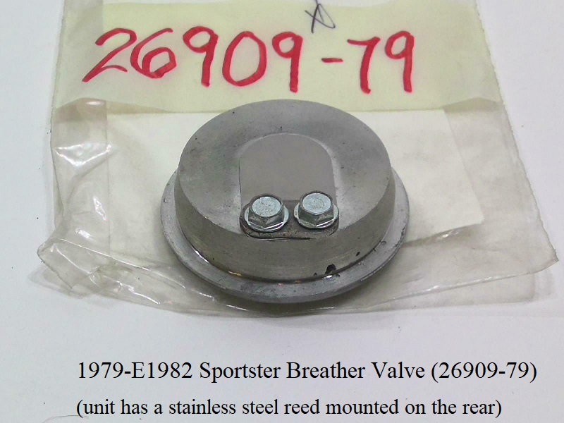
1979-E1982 Breather Valve
- Reed Valve Assembly (26909-79).
- Breather vent fitting thread size at the cam cover is 1/8“ NPT. 24)
- The external foo-foo valve and the six-inch metal vent tube at the front of the timing cover were done away with.
Instead, a one-way foo-foo valve was built inside the timing cover.
A rubber breather hose then ran from the generator drive area of the timing cover, at the 10 o’clock position.
It connected to the stock air filter so that any oil mist was fed back through the engine, making the EPA pollutocrats more happier.
(than they were with the idea of engine oil spraying out into the atmosphere)
The generator had a (1-5/8” O.D.) oil separator washer on the end of the armature shaft. 25) - The breather valve is a simple reed valve with a flap made of spring steel over a hole.
Unless it's visibly damaged, there's no reason to mess with it. 26)
If it stops up, you can try and spray some WD-40 in the hole to clear it.
- Removal:
- The reed can be removed with a standard bushing / bearing puller with a 5/8“.
- Replacement options / mods:
- In L1982, a new style crankcase breather valve was used in production.
The breather valve kit (26909-79A), which is functionally more durable and quieter than the early style reed valve, will fit 1979-E82 models.
The late style breather valve incorporates a rubber umbrella valve attached to the base plate along with a larger diameter oil slinger washer.
The oil slinger washer is bigger (1-3/4” OD).
These parts, used together, will replace the early style reed valve assembly and smaller diameter oil separator washer.
- It's a possible option for the 79-85 breather valve to be replaced with an external breather valve.
If you want to go this route, remove the internal valve as it will also change crankcase pressure with 2 valves in line.
Then, you might want to consider installing something like the external Krankvent or others.
Click here to see the Converting Head Breathers to Cam Chest Breather page in the Sportsterpedia.
That page is for an Evo conversion to cam chest breathing but the Krankvent and plumbing is shown.
You can also review this page in the Sportsterpedia Breather Venting / Relocation (especially the sub documents at the top of the page) - Click here to see the page on Adding a Secondary Vent Hose at the 6:00 Position.
This mod has been done with agreeable results to improve breathing.
Here's the reed valve as installed.
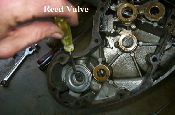 27)
27)
Here is the reed valve assembly front and back side.
 28)
28)
 29)
29)
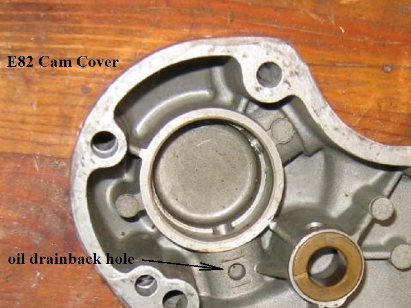
L1982 Upgrade
(Left) - E82 cover with the breather removed showing compartment below. 30)
(Right) - 81 Cam Cover Breather Compartment (with the rubber umbrella valve upgrade). 31)

L1982-E1984 Breather Valve
- Breather valve (26909-82).
- The crankcase breather valve was redesigned to incorporate a rubber umbrella valve attached to a metal disc installed in the base plate.
(along with a larger diameter 1-3/4“ O.D. slinger washer)
L1984-1990 Breather Valve
- Breather valve (26856-82)
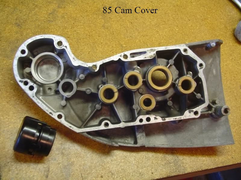
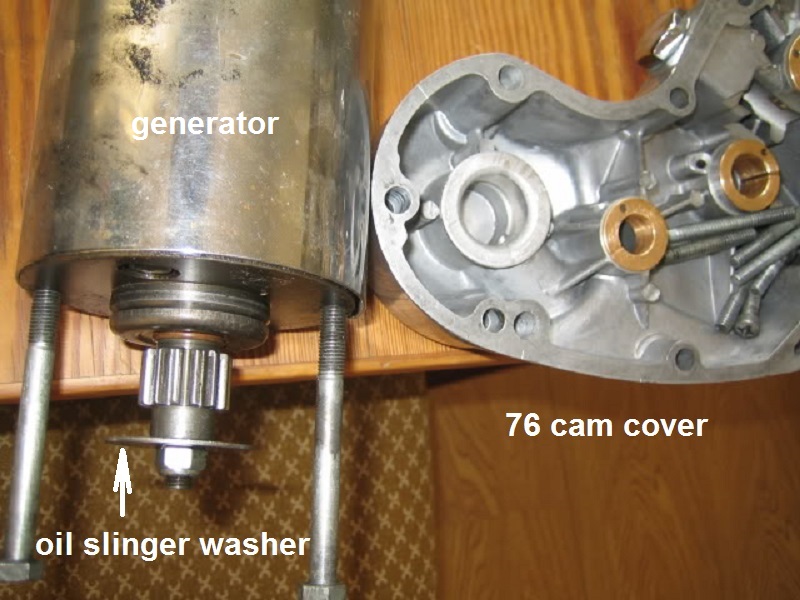
- The generator was moved and an oil filter was mounted in it's place. The oil slinger system was deleted for L84-up models.
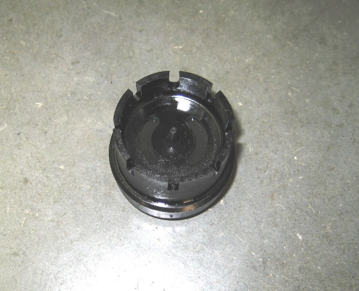
- The crankcase breather valve was redesigned to incorporate a baffle tube assembly (26917-84) with a rubber umbrella valve inside it.
The pic on the left shows the breather line coming out at the 10 o'clock position going up to the air cleaner.
The pic on the right is of an 85 cam cover with the foofoo valve (baffle tube) off to the left of it.
Umbrella check valve: 35)
Outside diameter:
26856-82 - 1.25”
Edge thickness (1/8“ in average): 36)
26856-82 - 0.036”
The pic below shows the left side (filter side) that faces into the cam box.
It's center inside diameter is slightly larger than the 1.25“ OD (-82) umbrella valve.
The two 'C' shaped slots that do the breathing have an OD of 1”.
1979-1990 Breather Valve Replacement Options / Mods
- It's a possible option for the 79-90 breather valve to be replaced with an external breather valve.
If you want to go this route, remove the internal valve as it will also change crankcase pressure with 2 valves in line.
Then, you might want to consider installing something like the external Krankvent or others.
Click here to see the Converting Head Breathers to Cam Chest Breather page in the Sportsterpedia.
That page is for an Evo conversion to cam chest breathing but the Krankvent and plumbing is shown.
You can also review this page in the Sportsterpedia Breather Venting / Relocation (especially the sub documents at the top of the page) - Click here to see the page on Adding a Secondary Vent Hose at the 6:00 Position.
This mod has been done with agreeable results to improve breathing.
Oil Slinger
Sub Documents
Crankcase exhaust air escapes from the gearcase through the external breather tube. 39)
Any oil carried still carried by exhaust air is separated from the air by an oil slinger on the generator drive gear.
The oil slinger is powered by the generator and deflects oil away from air leaving the breather outlet to atmosphere.
It spins oil away from the breather hole by centrifugal force and separates the oil mist in suspension with the exhausting air.
- 1952-1962 K/KH/Sportsters used a drive gear with an integral oil slinger (daisy wheel) on the end and pinned to the generator shaft.
It looks like a gear with a tinker toy connector glued on the end. It's a lathe machined affair combined with a spring loaded sleeve in the cover.
Just get rid of the timing cover sliding bush/spring if you want to upgrade to the big washer instead. 40)
The sliding bushing assembly makes the early slinger works as a “labyrinth” since the air has to travel through its center to get out.
That's why it's a better set up than the simpler washer setup. It doesn't allow for any oil to escape except if your engine is totally wetsumped.
But the early slinger will work without the sliding bushing, just not as good.
And you can't use the sliding bushing with the washer setup.- K and KH Models used gear (31071-52).
- 1957 XL Sportster used gear (31071-52A) with no nut or washer.
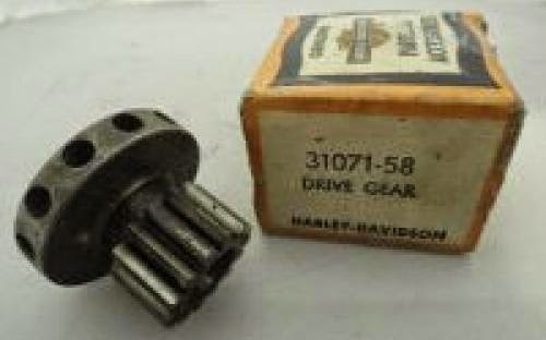
- 1958-1962 Sportsters also used a daisy wheel gear (31071-58) but now bolted to the generator shaft.
- L1962-1978 Sportsters used a more standard looking 14T gear (31073-63) used with a 1-5/8“ washer style slinger (31067-63).
Not as good but a lot cheaper to make. The washer itself looks to be just a normal fender washer.
You may find an in use washer with grooves stamped in it. Grooves are an old mod done by owners/wrenches (not the factory).
It is large enough in diameter to make installing the generator tricky at times.
5/16” fender washers come in 3 sizes. 1.375“ (common), 1.500” (hard to find), 1.625“ (real hard to find).
OEM is 1.625” although the 1.500“ washer usually works fine. The 1.375” washer may pass more oil out the vent than the bigger ones.
- 1979-1981 Sportsters used gear (31073-63A) with the 1-5/8“ slinger washer (31067-63).
- 1982-E1984 Sportsters used the same gear (31073-63A) with a 1-3/4” slinger washer (31066-82) to accommodate the larger crankcase breather valve.
To inspect or replace the slinger washer, remove the two bolts from the cam cover that hold the generator. 41)
Remove the wires from the generator and with a little fiddeling around, the generator will come out. The washer is on the end of the armature.
Make sure to put a new grade 8 nylock nut on if you remove the old one. They should only be used once or they lose their grip in that hot, oily environment. 42)
Check the oil separator bushing to bore fit in the cover. It should be a light press fit.
If it is loose, you can probably remove it, clean up the boss with brake cleaner and reinstall the bushing with Loctite or epoxy. 43)
| 1952-1956 K/KH or 1957 XL Sportster (pinned) Generator Drive Gear / Oil Slinger 44) | 1958-1962 Sportster (threaded) Generator Gear / Oil Slinger (31071-58) 45) | 1963-Later Oil Slinger Washer (31067-63) 46) |
 |  |  |