Table of Contents
This is an old revision of the document!

IH: Oiling & Lubrication
Engine Oil System
Engine Oiling
General Statement
The Sportster Oiling Cycle is defined in the FSMs.
However, that description is vague in some of the intricate transitions of the oil path in the engine.
This page is an attempt to clarify some of the gray areas from the FSM's descriptions with further description and pictures. 1)
Engine Pressures
Oil Pump Pressure
The oil pump doesn't make pressure. All it does is create flow.
However, the restrictions in the engine back up that flow and create pressure.
So in essence, the oil delivery system does make pressure and it can be measured with a gauge.
The oil pump is non-regulated and delivers its entire volume of oil under pressure to the oil filter mount.
Measurable oil pump pressure is a result of engine restrictions, as mentioned, on the pressure side of the pump.
(i.e. lines, routing, holes and galley sizes)
The engine has a force-fed (pressure type) oiling system incorporating oil feed and return pumps in one pump body with a check valve on the feed side. 4)
- The feed side of the pump forces oil to the engine to lubricate;
- Lower connecting rod bearings
- Rocker arm bushings
- Valve stems
- Valve springs
- Pushrods and tappets
- The scavenge side of the pump returns oil from the bottom of the gearcase and crankcase sump to the oil tank.
Also, it's not unusual to get air out the oil return line (to the tank). 5)
It's a dry-sump system with a gerotor oil pump that's designed to keep the engine sump as dry as it can.
When there's no oil to suck up, it pumps a little air instead into the oil tank.
That's the way it's supposed to work.
See also, Oil Tank Pressure in the REF section of the Sportsterpedia.
Crankcase Pressure
See also IH Crankcase Pressure and Engine Breathing in the REF section of the Sportsterpedia.
Crankcase air pressure is mainly generated by the up and down movement of the pistons.
The downstroke of the piston causes the volume underneath the pistons to decrease which puts pressure on the oil in the crankcase / sump respectively.
This pressure is multi use;
- It helps to push sump oil up and out the scavenge passage to the return side of the oil pump.
- It also initiates the splash and mist process as the compressed air above the oil is ready to spring up when the piston rises.
Then the upstroke of the piston creates an upward vacuum bringing some of the oil from the sump with it.
With little to no (piston ring) blow-by and a check valve on the breather system;
Crankcase pressure is essentially cycling between atmospheric and negative (pressures) as the pistons go down and back up.
(remember, due to the common crankpin 45 degree design, a Harley motor is a variable volume crankcase, unlike most motors) 6)
This creates splash oil which is bounced about in the crankcase.
This also creates an air / oil mix when tiny particles intertwine with the oil in suspension.
The two don't actually mix as does sugar and water.
So separating them back apart is fairly easy if you add an obstacle for that 'mix' to collide into.
Collision is the means in which most air / oil is separated. Everything the air / oil mist runs into on the way to the vent separates oil from air.
On 57-E84 models, the final obstacle for separation is the oil slinger near the breather vent.
On L84-85 models, the final separation obstacle is the breather valve in the cam cover.
The piston motions create a pulsating blast of air pressure (push pull condition as each piston rises and falls).
Static oil pump pressure has already been dissipated by the time it reaches the crankcase.
(although it takes static oil pressure to get the oil from the pump to the crankcase thru restrictions in the feed path)
Likewise, crankcase (CC) pressure will have a constant change in velocity.
Oil in the crankcase adds resistance to the air pressure generated (raising the pressure).
Gravity oil drains from rocker boxes;
Returns oil to the crankcase via the drain ports in the heads / cylinders and to the gearcase via the pushrod tubes.
Some CC Pressure is needed
Some of the oil is picked up by the piston upstroke and mixed with the air pressure in the form of mist.
The mist and splash oil lubricates crankcase components.
And they are also carried into the gearcase compartment to help lubricate the cams and pinion / oil pump gears.
Splash and gravity oil from the connecting rods, crankshaft, rocker boxes and head/cylinder drainage holes serve to lubricate;
- Cylinder walls
- Pistons, piston pins
- Cam gears and bushings
- Main bearings
Excess CC Pressure is vented out of the engine
See also Crankcase Ventilation in the Sportsterpedia.
Unvented crankcase pressure will simply build up inside the engine and eventually blow out geaskets / seals in the engine.
The pressure (even though needed) would build high enough to be detrimental to the engine.
So unusable high pressure is vented out of the engine to keep in (regulate) a certain amount of usable internal pressure.
Oil Tank Pressure
See the full article, Oil Tank Pressure, in the REF section of the Sportsterpedia.
There should not be any noticeable pressure in the oil tank.
During normal operation;
With the tank cap / dipstick removed, tank pressure is vented to atmosphere from the top of the tank.
With the tank cap / dipstick installed, tank pressure is vented to the cam chest.
During shutdown;
The oil tank vent is connected to the cam chest and the cam chest is vented out the breather valve in the cam cover.
So if you have pressure in your oil tank and the vent to the cam chest is not blocked then the cam chest is also pressurized.
If the cam chest is holding pressure, then your breather valve can not be venting properly.
Bottom line is that if the vent system is working properly, you shouldn't have excessive pressure build up in the oil tank. 7)
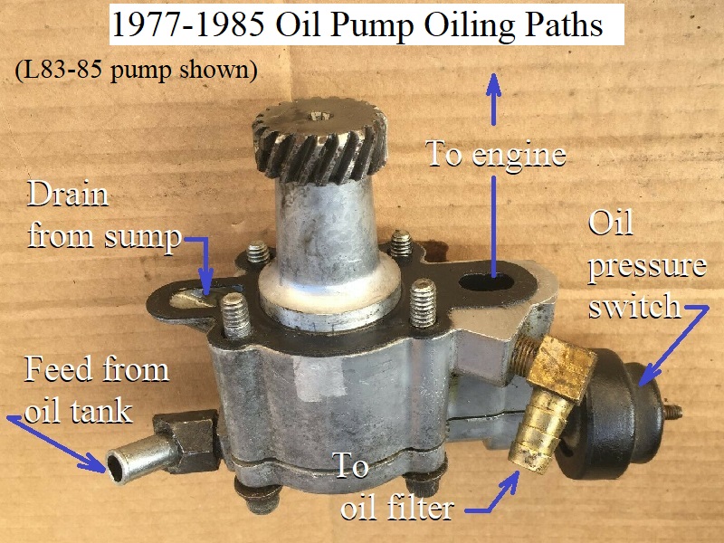
1977-Up Oil Pump Feed
See also the Evo oil pump section of the Sportsterpedia.
Oil is gravity fed from the oil tank to the oil pump.
- In essence, the oil tank is mounted above the oil pump and the feed line runs down to the pump.
However, there is also a vacuum on the feed line to the pump.
- Once the oil pump feed gerotors begin spinning, they also pull a backdraft (or vacuum) on the incoming oil supply line. 8)
It's an added part of the system once the pump starts turning(in addition to the force of gravity). - As the volume between the feed gerotor gears increase (with engine RPM), the suction on the feed line also increases. 9)
- Likewise with lower RPM, the suction decreases.
- The oil leaves the pump internally to the engine thru a check valve cartridge in the pump and into a passage in the cam cover.
- The oil pump feed gerotors send pressurized oil up through a cavity in the cam cover to the crankpin and then up to the rocker arms.
| 77-85 Oil Pump Oiling Paths. |
 |
Changing / Draining Engine Oil
Oil Tank Capacity
| 1970-1978 | 3 quarts |
| 1979-1981 | 4 quarts |
| 1982-1985 | 3 quarts |
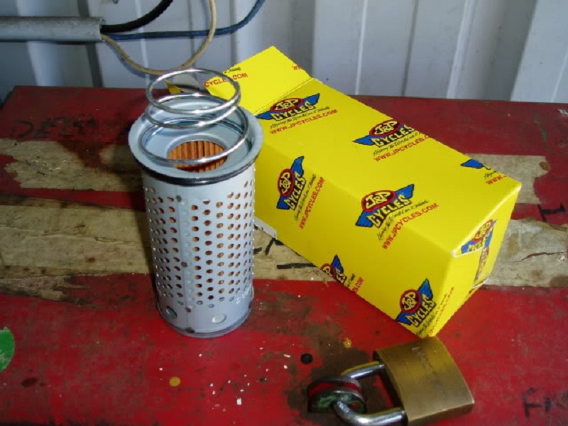
Oil Filter
| 1970-E1980 | Drop in element (63840) |
| L1980-E1984 | Spin-on |
| L1984-1985 | Spin-on |
Oil Filter Mount
See also Remote Oil Filters in the REF section of the Sportsterpedia.
—– 1957-1978 XL - XLH Models —–
XLCH models did not have an oil filter.
XL / XLH models have an oil filter mounted inside the oil tank.


—– 1979 Models —–
1979 models didn't come with an filter as a base sale from the MoCo.
However, an oil filter kit was debuted in 79 as an accessory item.
So some may have them and others may have not.
Oil filter mounting threads are M16 x 1.5mm. 12)
—– 1980-1981 Models —–
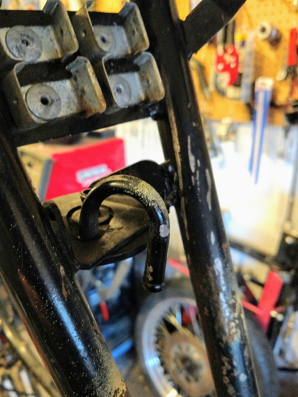
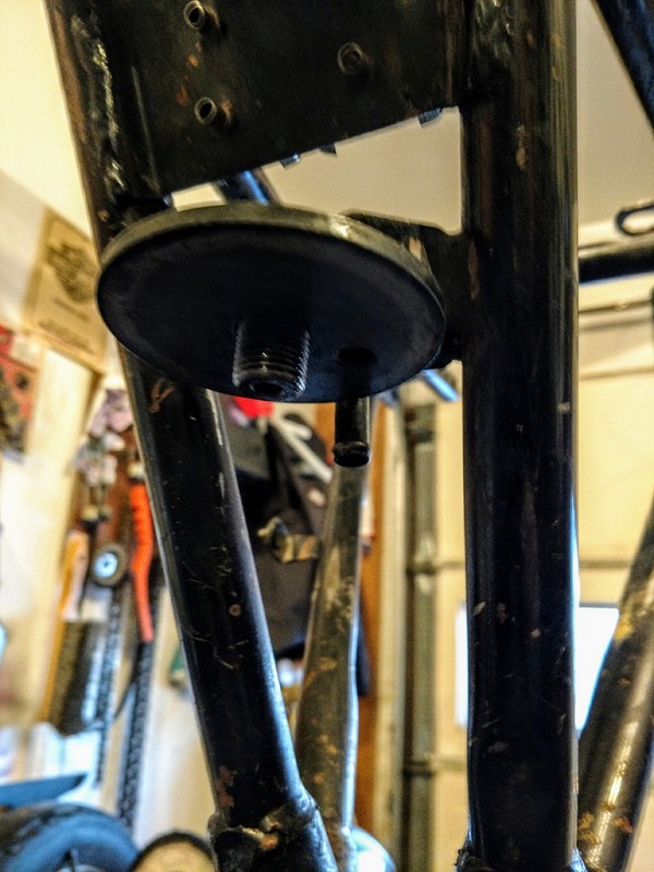
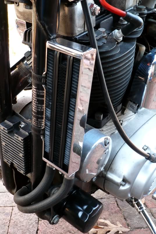
The oil filter was relocated on 1980 and up models and they were fitted with an external oil filter.
The filter mount is located on a bracket between the engine and the oil tank.
It's under the seat in a awkward place to work with. 13)
Oil filter mounting threads are M16 x 1.5mm. 14)
| Wide angle of filter location 15) |
 |
| Oil filter mount on 81 model. 16) The hooked hose fitting is connected to the oil return hose from the pump. The straight hose fitting in the middle goes to the oil tank. 17) |
|||
 |  |  | 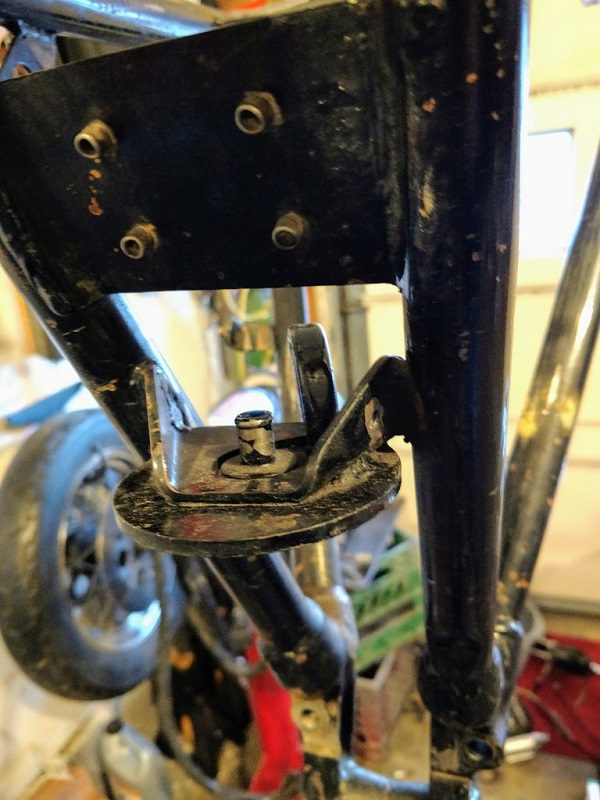 |
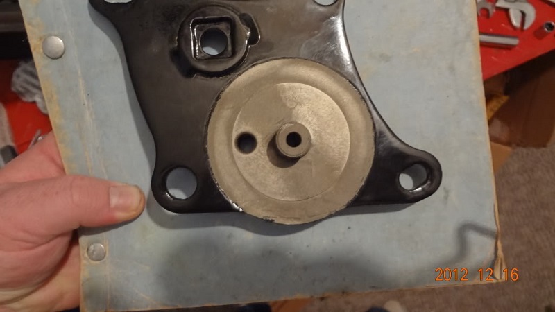
—– 1982-E1984 Models —–
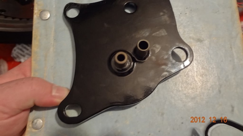
The filter mount is mounted on the lower left front engine mount.
This has also been a popular practice on earlier bikes.
| 82-E84 lower front motor mount / filter mount. 18) | |
 |  |
Oil filter mounting threads are M16 x 1.5mm. 19)
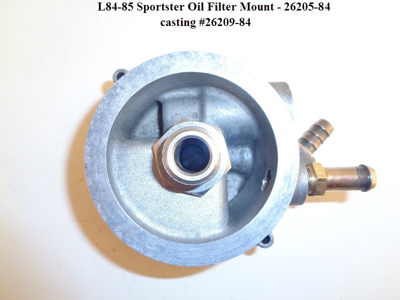
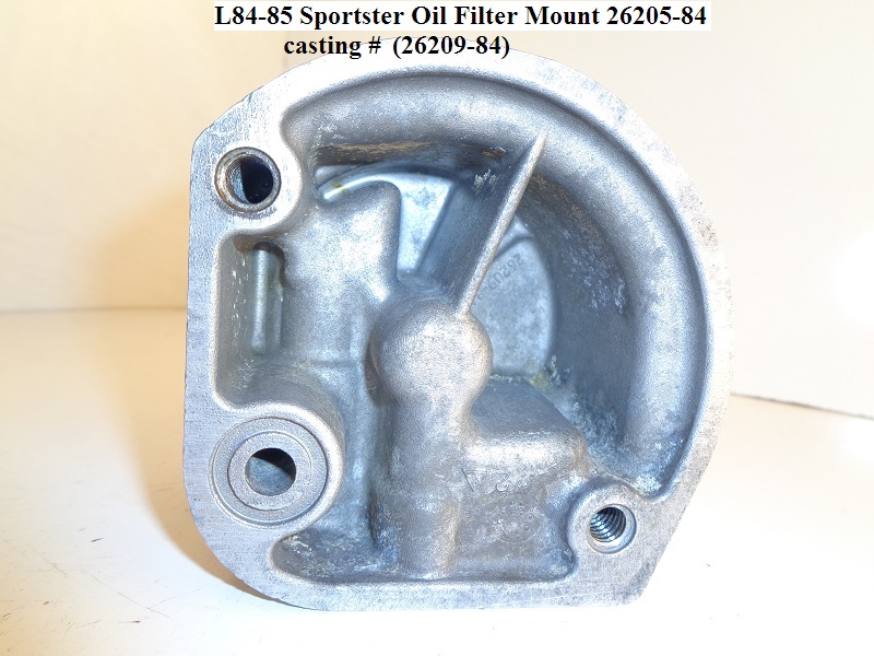
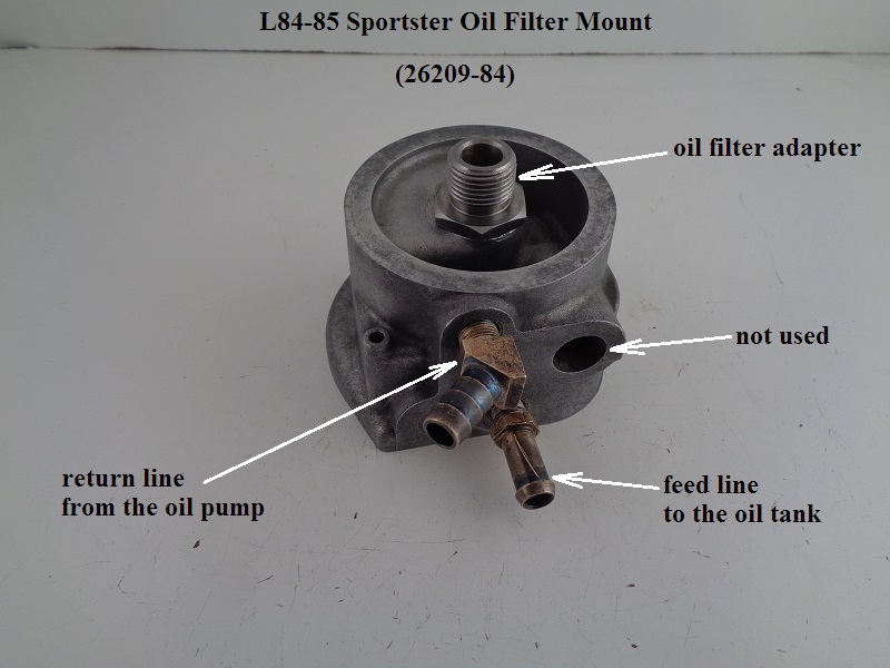
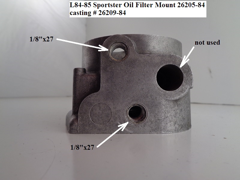
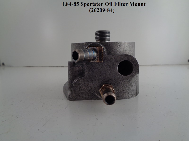
—– L1984-1985 Models —–
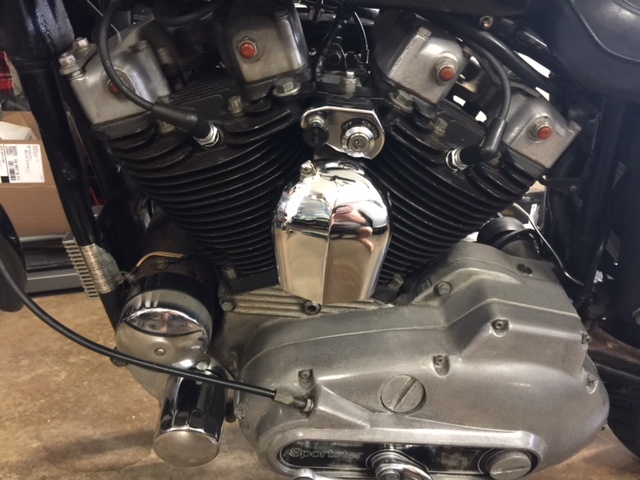
The oil filter on alternator ironheads is where the generator used to be. 22)
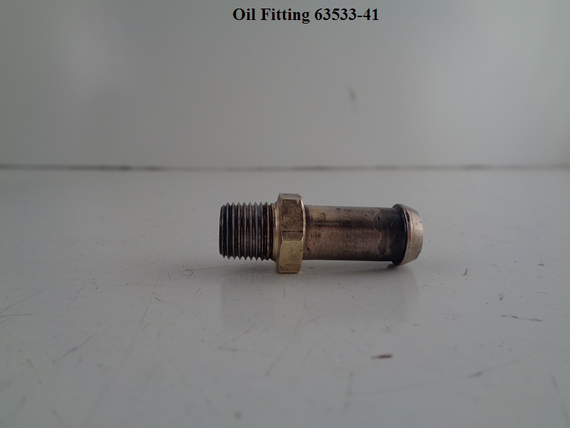
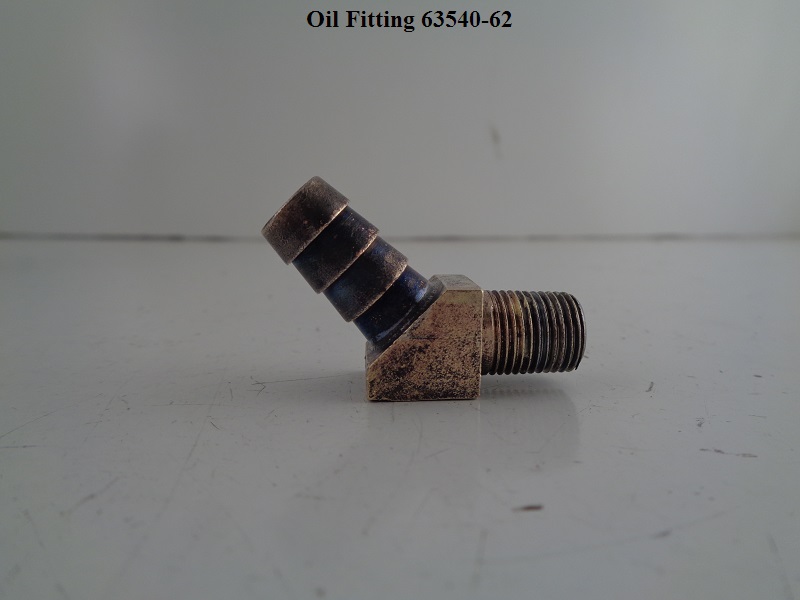
Two fittings (feed and return) are on the right case below the filter.
Room was made there due to the new alternator location.
This change was made along with the breather baffle tube assembly installed in the cam cover.
The oil slinger system was eliminated.
Oil filter mounting threads are 3/4“-16.
 |  |  |
 |  |  |
 |  |  |
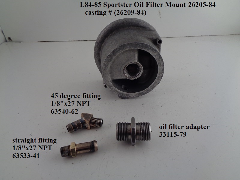
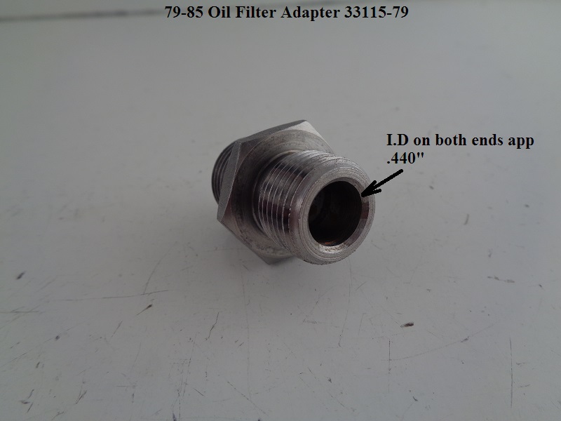
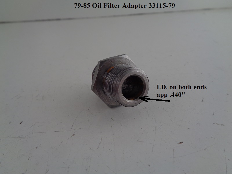
Oil Filter Adapter (L84-85)
The threads on each end of the oil filter adapter are the same.
The I.D. on each end is also the same.
The adapter can be installed from either side as there is no check valve / check ball involved with the oil filter mount.
Installation:
Thread the adapter into the filter pad. No thread dressing is suggested by the FSM.
However, a light coat of anti-seize would protect the threads upon later removal of the adapter (if necessary).
Torque: 8-12 ft/lbs. 23)
Dims:
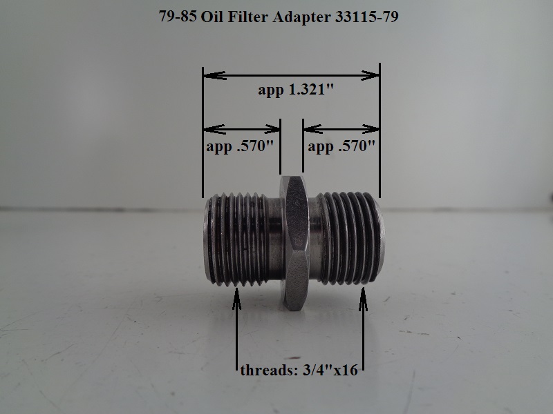 |  |  |
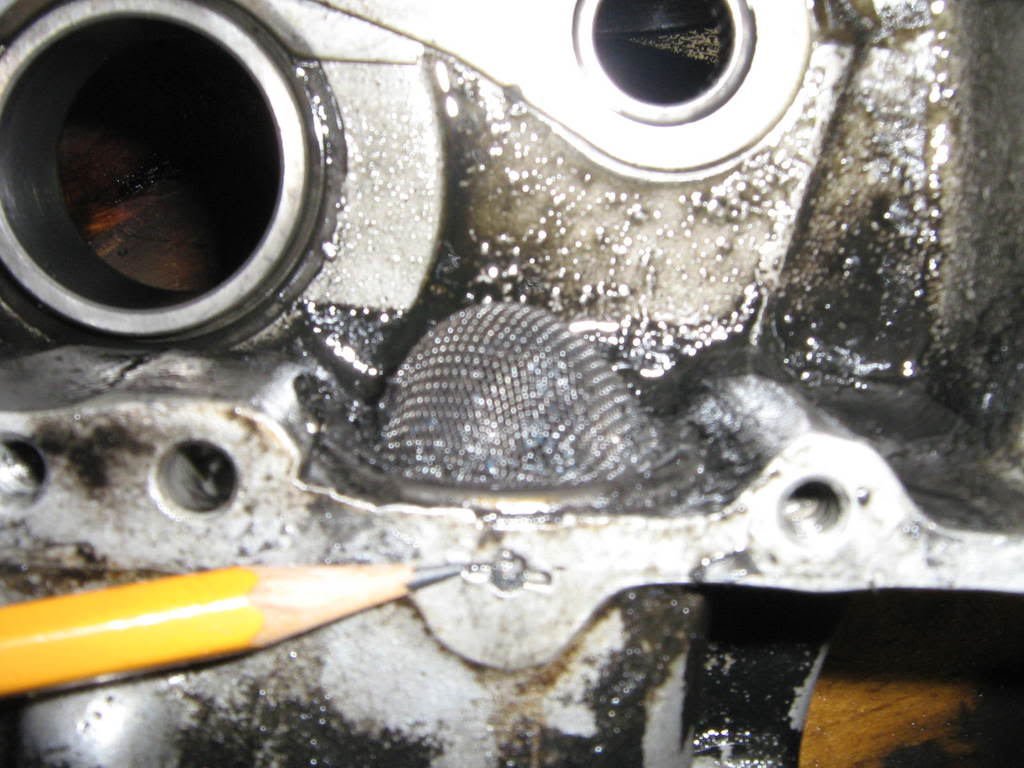
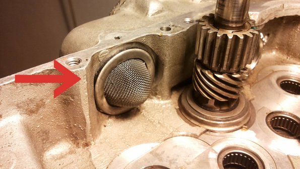
Crankcase Oil Strainer (1957-1976)
- If you've split the cases and the screen is in good shape, you don't have to take it out. Hit it with some compressed air and see if it needs replacing. 24)
 25)
25)  26)
26)
The strainer is held in place by this pin. It is staked into place with the two horizontal lines radiating from the it. To remove strainer, you must first remove the pin. Tear the screen from the strainer and place pliers on the pin inside (the now destroyed strainer) and wiggle the pin out. Strainers and strainer gaskets are available for replacement. 27)
Engine Oil Cycle (1976 and Earlier)
- Oil is gravity fed from the oil tank to the oil pump. 28)
- A check valve in the oil pump prevents the oil from draining into the engine by gravity.
- Then, the oil pump supplies pressurized oil into a hole in the cam cover.
- That pressurized oil is forced up the lines (between the cylinders) to the rocker box by the oil pump.
- That is the vertical end of responsibility (pressure wise) for the oil pump.
- In the rocker boxes, oil gathers and splashes over rocker arm bearings and rods, valve stems, valve springs and pushrod sockets.
- Before the oil reaches the rocker lines, it splits off to a hole through the pinion shaft (to get to the rod bearings).
- This is the horizontal end of responsibility (pressure wise) for the oil pump.
- From here on, oil travels through the engine by way of gravity, vacuum and splash motion.
- Oil drains from the heads through passages in each cylinder.
- Then it flows into two holes in the base of each cylinder while lubricating the cylinder walls, pistons, rings and main bearings.29)
- Oil flows from the rocker boxes into the gearcase compartment through the pushrod tubes.
- Parts lubricated by this include the pushrods, tappets, tappet guides and tappet rollers and cam gears.
- Oil accumulated in the crankcase base is scavenged by the flywheels to the breather oil trap.
The rotary breather valve is timed to open on the downward stroke of the pistons.
This allows crankcase exhaust air pressure to expel scavenge oil from the crankcase breather oil trap into the gearcase.
The breather valve closes on upward stroke of the pistons, creating vacuum in the crankcase.
- This splash oil blown from the crankcase to the gearcase lubricates the generator drive gear, cam gears and cam bearings.
- Gearcase oil flows through the fine mesh oil strainer preventing foreign particles from entering the scavenge section of the oil pump.32)
- Engine oil returns to the oil tank by the scavenge side of the oil pump and also supplies oil to the rear chain oiler.
Engine Oil Cycle (1977 to 1985)
- Oil is gravity fed to the gerotor type oil pump. Oil enters the feed section and fills a cavity under the feed pump. Oil is transferred from the inlet cavity to a one way check valve located in the outlet line. 33)
- The check valve prevents gravity oil drainage from the oil tank to the engine and acts as a restriction to activate the pressure switch. The check valve is set to open between 4 psi and 6 psi of oil pressure. 34)
- As the oil pump pressurizes, it causes the oil pressure indicator light, sending unit to activate and the check valve opens. With the check valve open, oil flows into the right case half through a hole located in the oil pump gasket surface and into the gearcase cover passage through a hole in the gearcase cover gasket. 35)
- Oil is routed to the crankshaft and to the head areas. Oil enters a hole in the pinion gear shaft and travels to the right flywheel then through the flywheel to the crank pin. Oil is forced out of the crank pin through 3 holes located to properly lubricate the rod bearing assembly. 36)
- Oil that bypasses the pinion gear shaft travels upward through the gearcase cover to the right crankcase and through a channel in the crankcase to the overhead lines to both front and rear intake rocker arm shafts, lubricating the rocker arm shafts, bushings, intake valves and pushrods. 37)
- Oil continues around a groove machined in the outside diameter of the large end of the rocker arm shaft and through the rocker arm arm cover to the exhaust rocker arm shaft lubricating the rocker arm bushings, valves and pushrods in the same manner as is described for the intake shafts. 38)
- Oil collected in the pushrod area of the heads flows down the pushrod covers to lubricate the lifters. The lifter's rollers are lubricated by oil draining into the gearcase through the 2 drain holes in the lifter bodies. 39)
- Oil collected in the valve spring pockets drains to the flywheel compartment through horizontal holes in the cylinders. Oil returning from the heads, rod assembly and gearcase collects in the sump area below the flywheels. 40)
- Oil collected in the sump area returns to the scavenger section of the oil pump through a passage located in the rear section of the pump. Oil flow to the pump is accomplished by the scavenger effect of the oil pump and the pressure created from the downward stroke of the pistons. 41)
- Return oil fills a cavity above the scavenger section of the pump which transfers return oil to the outlet side of the pump and sends the oil back to the oil tank.
- All engine breathing is accomplished through the gearcase into the breather system. Any oil still carried by the exhaust air is centrifugally separated from the air by an oil slinger on the end of the generator drive gear shaft.42)
- Crankcase exhaust air is routed through a one way check valve to the air cleaner. 43)
Engine Oil Pressure (57-85)
See also Sportster Oil Pressure (57 to Present) in the REF section of the Sportsterpedia.
On ironheads, 80% of oil pressure is sent to the bottom end and 20% is sent to the top end. 44)
The oil pump is non-regulatory and delivers its entire volume of oil under pressure to the oil filter mount.
When an engine is cold, the engine oil will be more viscous (ie., thicker).
During start-up of a cold engine, oil pressure will be higher than normal and oil circulation will be somewhat restricted within the oiling system.
As the engine wams to normal operating temperature, the engine oil will warm up also and become less viscous - oil pressure will decrease.
When an engine is operated at high speeds;
The volume of oil circulated through the oiling system increases, resulting in higher oil pressure.
As engine speed is reduced, the volume of oil pumped is also reduced, resulting in lower oil pressure.
Ironhead engine oil pressure was measured (by the MoCo) with a pressure gauge at the oil pump.
See expected oil pump pressures below (per FSM's):
Gauge mounted at oil pump:
As checked with hot oil and a gauge at the oil pressure switch location at the oil pump.
The oil pressure switch has to be removed for the gauge to be installed.
1957-1969: 45)
Minimum: 3-7 psi (idle, with spark retarded)
Normal riding conditions: 10-14 psi (6 psi at 20 mph)
1970-1978: 46)
Minimum: 3-7 psi (idle)
Maximum: 15 psi (60 mph in high gear)
Normal riding conditions: 4-15 psi
1979-1985: 47)
Minimum: 4-7 psi (idle)
Maximum: 10-20 psi (3500 rpm)
Normal riding conditions: 4-15 psi
Note: On a cold startup, expect pressure to reach ~60 psi 48)
Checking Oil Pressure
See also Installing an Oil Pressure Gauge in the Sportsterpedia.
When checking oil pressure, it's important to note that you are not testing pressure at a dead stop standpoint.
The oil is flowing into the engine at the same time you are testing from a still test site.
Likewise, the resulting pressure reading is a reflection of residual pressure while that pressure is being manipulated.
(by oil flow as well as the current viscosity)
According to the MoCo (FSMs), the oil pump is the prime testing point of oil pressure to the engine.
The procedure is to take the oil pressure gauge off and install an oil gauge there.
This works if you have verified that you do have oil flow to the engine and just want to check the pressure at the pump.
This takes the oil pressure switch as well as the oil light out of line.
However a tee can be added inline for a dedicated gauge.
You can either mount a permanent gauge to the tap or plug it off until needed.
This will keep the switch and the oil light inline and working if you need it.
Low Oil Pressure
The oil pressure light can fluctuate on and off for many reasons.
It doesn't necessarily mean you have low oil pressure (or flow) to the engine.
However, it does warrant immediate concern and diagnosis.
In fact, at idle, the oil pump check valve is barely opened past it's cracking pressure.
Low revs at idle can cause the oil light to flicker off and on.
First, verify that the oil pressure light is functioning properly:
- Check for a loose or faulty connection at the oil pressure switch.
- The wire connection at the oil pressure switch has to be tight so vibration won't cause intermittent signal loss to the oil light.
- Inspect the signal wire between the light and the pressure switch for kinks, cuts or faults.
- Make sure it's not grounding out on nearby metal parts (especially melted PVC jackets under wire ties).
- Run a continuity test on the entire length of wire with a multi-meter.
- Repair or replace the wire as needed.
- Verify the light is not faulty or burnt out.
- Disconnect the wire at the oil pressure switch.
- Run a jumper wire off the (+) side of the battery to the end of the oil light wire.
- Verify it lights up and then bump the light by hand to verify vibration doesn't affect it.
Verify the oil pressure switch is working properly:
- The oil pressure switch is a spring loaded diaphragm.
- With insufficient pressure pushing against the spring mechanism, the switch is normally grounded.
- This grounds out the circuit to the light, and it stays unlit.
- With adequate oil pressure against the spring, the ground contact is broken which lights up the oil light.
- If the pressure switch is stuck in the closed position;
- The circuit stays grounded and the light will not come on.
- If the pressure switch is stuck in the open position;
- The light will come on during startup and stay on during engine operation.
- If the pressure spring is changed with a stiffer spring (57-76);
- The oil pump will not make sufficient pressure to overcome the spring pressure at warm idle.
- The oil light will illuminate on a cold startup due to startup oil pressure.
- The light will then go out when the oil heats up (lowered pressure against the spring).
A faulty oil pump check valve will not turn off the oil light:
The restricted orifice in the check valve creates the back pressure to actuate the oil pressure switch.
- If the check valve is stuck in the open position;
- The oil still has to travel through the restricted orifice in the check which creates backpressure to actuate the pressure switch → oil light.
- If the check valve was stuck in the closed position;
- Pressure would still build up inside the oil pump and actuate the oil pressure switch and then the oil light.
- This would seem like everything is fine with the engine running and the light off.
- However, with the check closed, no oil would enter the engine.
Check for possible causes of low oil pressure:
- If the tank is empty, obviously oil pressure will be low.
Check for oil returning to the oil tank. - The oil filter (if applicable) could be restricted or plugged up.
- The oil lines may be pinched / collapsed, leaking or stopped up.
Inspect the oil lines. - There has been occasions where silicon (placed on the oil pump gasket during installation) had made it's way into orifices inside the engine.
You can blow compressed air thru oil inlet and outlets in the engine.
You can also blow out the oil lines. - The oil check valve could be stuck closed.
- No oil to the top end:
- Make sure the rubber grommets on each end of the stock rocker feed lines are not partially plugging the ends of the rocker feed lines.
Then remove the allen-hex rocker spindle plug from the front exhaust rocker spindle, at the right-hand side of the rocker box.
Oil should come out there if you have flow with the engine running. 51) - You can loosen or remove the 1/8” NPT pipe plug from the right side, front corner of each rocker cover.
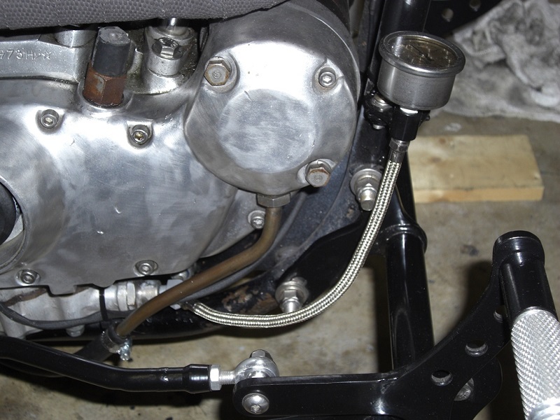
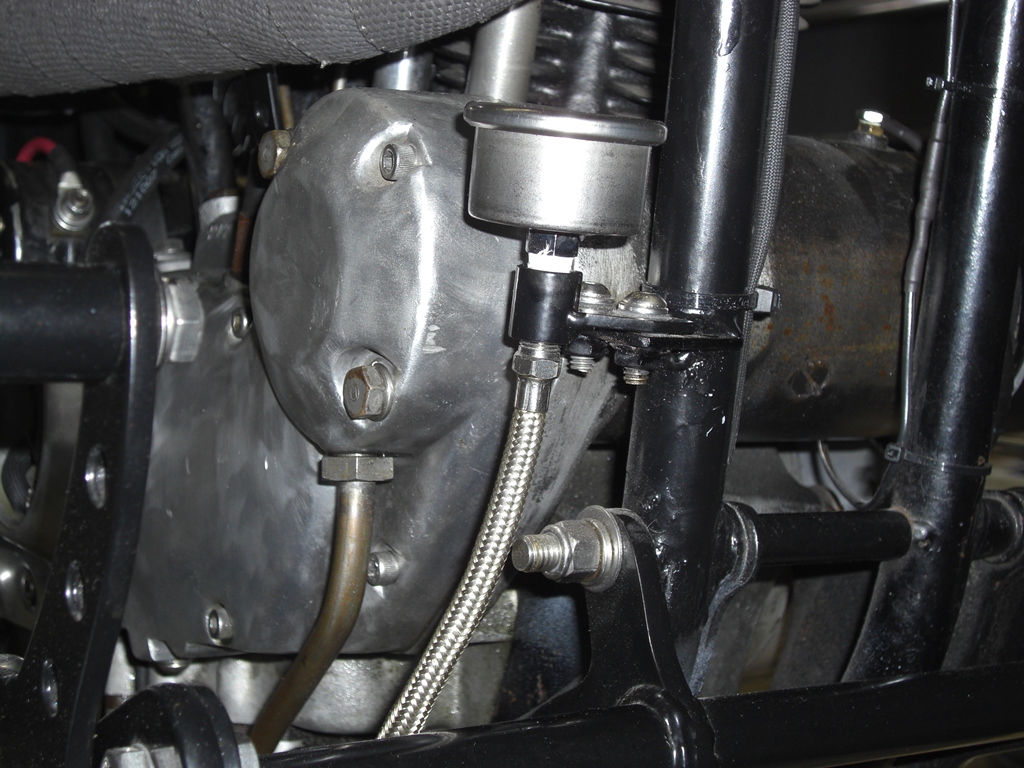
With the engine at idle, you should get a small amount of oil plopping out (not shooting out like a fire hose). 52) - You can also use the same 1/8“ plug hole to install a barb and clear hose to visually inspect for oil flow.
 53)
53) - Check the pinion shaft to bushing clearance to the specs in the FSM.
If the fit is overly loose, this condition will not allow oil to be transferred up the lines at low speed.
Oil will just be bled out into the cam chest until RPM sends and over-runs more oil than can be spilled at the bushing.- If the fit is out of spec, you'll need to replace the bushing. 54)
- Then line ream it using a special reamer through an old right-hand crankcase half to use to guide to get it in square.
- On 76< motors, it's best to eliminate that possibility before spending time and money yanking the engine out of the frame and inspecting the oil pump.
(and before spending money getting a new pinion bushing reamed with the special tooling etc.) 55)
- The oil pump could be weak or malfunctioning.
- 76< pumps:
- If the pump shaft seal is blown, then the scavenge pump will continue to function because the pump pressure is higher than scavenge pressure. 56)
So oil will flow from your pump down the shaft into the scavenge pump and goes back to the tank from there.
It's possible the pump got some trash in it and got scarred and now just doesn't pump very well.
It's a nasty job getting the thing off, made doubly nasty if you don't find anything wrong.
If you have an oil flow problem from the pump, you can either rebuild it or put a new one on just to make sure that this is not the problem.
If it isn't the pump, then start looking for leaks.
If oil is not returning to the oil tank:
Check the oil lines:
- Pull the feed line from the engine / pump.
- Verify that oil from the tank will voluntarily flow out the end.
- If not (and the tank has enough oil), check the vent line.
- The vent line runs from the tank into the crankcase where tank pressure is vented to atmosphere.
- Verify this line is not pinched or stopped up (not allowing pressure to equalize in the tank).
- Pull the line at the engine, induce air into the line and check that the air is coming into the tank.
- Pull the return line from the engine / pump.
- Place a spare hose on the return fitting and to a catch can.
- Roll the engine over by hand and verify that oil will shoot out of the fitting.
Remove and inspect the oil pump.
The oil pump supplies pressurized oil into a hole in the cam cover.
That pressurized oil is forced up the lines (between the cylinders) to the rocker box by the oil pump.
That is the vertical end of responsibility (pressure wise) for the oil pump.
Before the oil reaches the rocker lines, it splits off to a hole through the pinion shaft (to get to the rod bearings).
This is the horizontal end of responsibility (pressure wise) for the oil pump.
With this pressure comes a certain amount of oil flow from the oil pump.
With a weak oil pump, there will be less pressure forced up the oil lines.
This will result in less oil reaching the rockers.
But, not necessarily less oil reaching the rod bearings (depending on degree of pump pressure reduction).
How much oil loss to the rockers is acceptable is yet to be determined.
However, the MoCo had to have accounted for a certain amount of pressure loss from the pump during the engineering phase.
But, the service limit for oil pressure was not detailed in the FSM.
- The scavenge and / or feed side of the pump may be damaged or not working properly.
- 77-85 oil pump checks.
- Oil Pump check valve:
- Check for a stuck closed check valve.
- Open the pump cover and push a small screwdriver or suitable metal rod into the hole in the check valve.
- The valve should be closed and the rod should push back on the internal spring with ease.
- If it is stiff, remove the check from the pump body and then remove it's O-ring seal.
- Soak it in solvent while pushing in and working the valve open and closed until it is easy to move with the rod.
- If it won't spring back, replace the check valve.
- Check that the feed and scavenge gerotors aren't damaged or scratched bad enough to warrant replacement.
- Check that the gerotor keys (solid pins on the gearshaft) are not sheared.
Oil Pressure Switch
See also in the Sportsterpedia:
* Homemade Oil Pressure Light in case you don't have one.
* Testing the Oil Pressure Switch

The oil pressure switch (for the oil light) is a pressure actuated diaphragm type on / off switch basically.
The diaphragm is spring loaded and held against it's contact point with the engine shut off or when oil pressure is too low while running (closed circuit).
When the engine is fired up, oil pressure builds in the oil pump and pushes the oil switch off it's contact point.
This opens ground to the switch and de-activates the oil light (open circuit).
Oil pressure is sensed by the oil pressure switch.
Thicker oil is harder for the oil pump to push thru the engine restrictions but the positive displacement oil pump keeps turning.
The combination of thicker oil (when cold) and constant addition of oil by the oil feed side creates higher oil pressure in the pump.
By the time the engine reaches over 1000 to 1200 rpms, the oil starts heating up and flows faster thru the engine restrictions.
The thinner, more free flowing, oil lowers oil pressure inside the oil pump (more flow means less oil backing up
the pressure).
The lower pressure allows the switch diaphragm spring to relax, moving the contact back toward it's seat (which could close the circuit / light the light again).
The oil check ball / check valve regulates a pocket in the oil pump to keep enough pressure in there to keep the light from coming on during operation.
Cold cranking oil pressure can reach between 30 PSI and upwards of 60-100+ PSI.
Oil pressure will vary from 4-15 PSI under normal riding conditions.
However, idle oil pressure will vary from 3-7 PSI.
So, at idle, the oil pump check valve is barely opened past it's cracking pressure (not to it's end of travel).
In the Case of a Defective Oil Pump Switch:
This switch opens and closes the contacts to the oil pressure light.
The oil light is important to have since if it is not working, it can be assumed that you have little to none oil flow to the engine.
If the pressure switch doesn't operate the light it should be checked for proper operation or replaced.
For the $30 or whatever you save by not buying the switch, it's just not worth it to not have the low engine pressure idiot light working. 58)
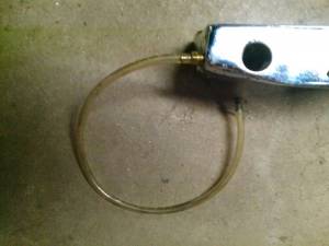
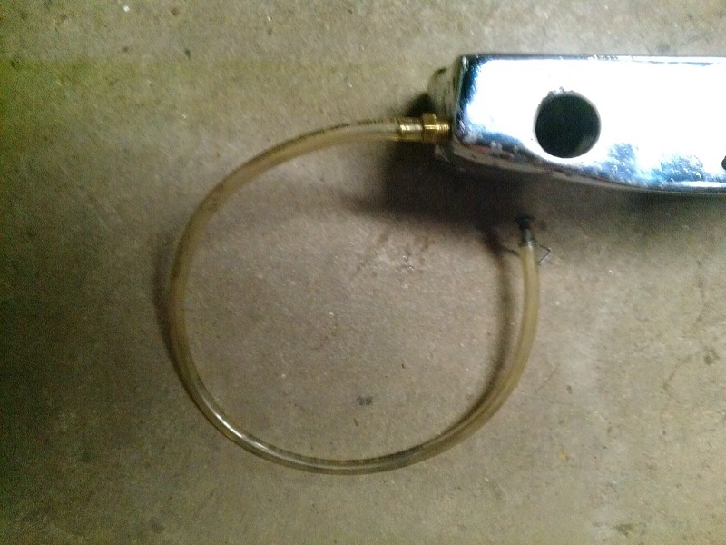
If your motor is ready to run and you need to test it then you can connect a piece of clear hose so you can see oil in it.
Don't plug the end till you've primed the pump (with ignition off kick it over a few times until oil comes out the clear pipe where the pressure switch lives).
Replace a defective switch as soon as possible.
Oil Pressure Switch Pics
 |  |  |
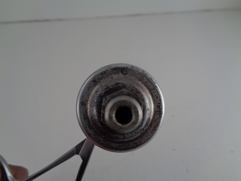 | 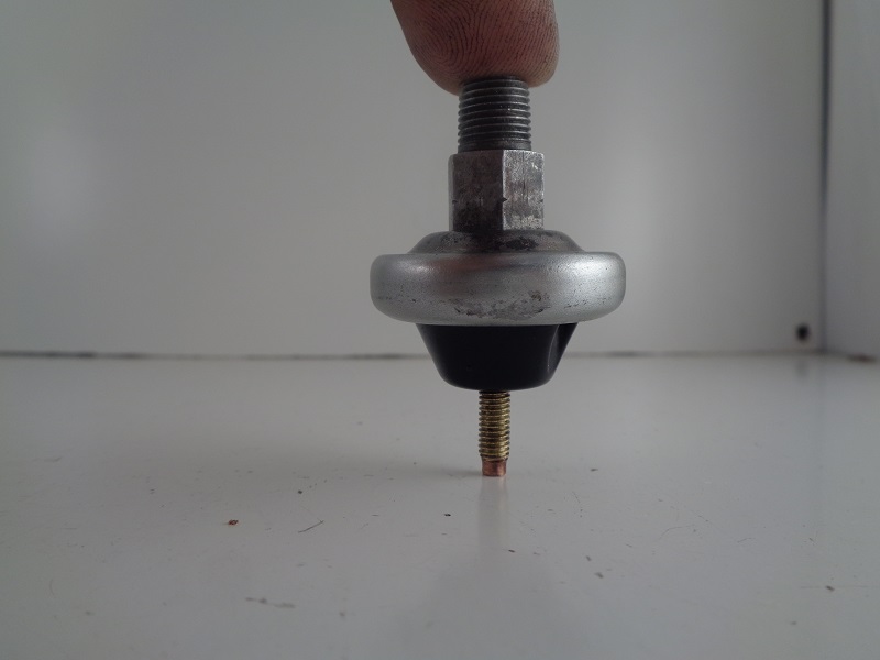 | 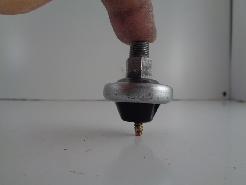 |
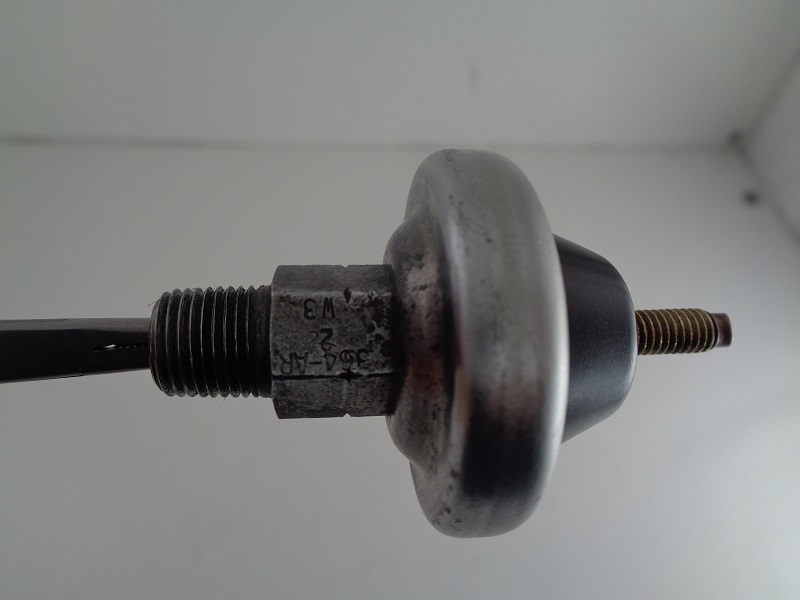
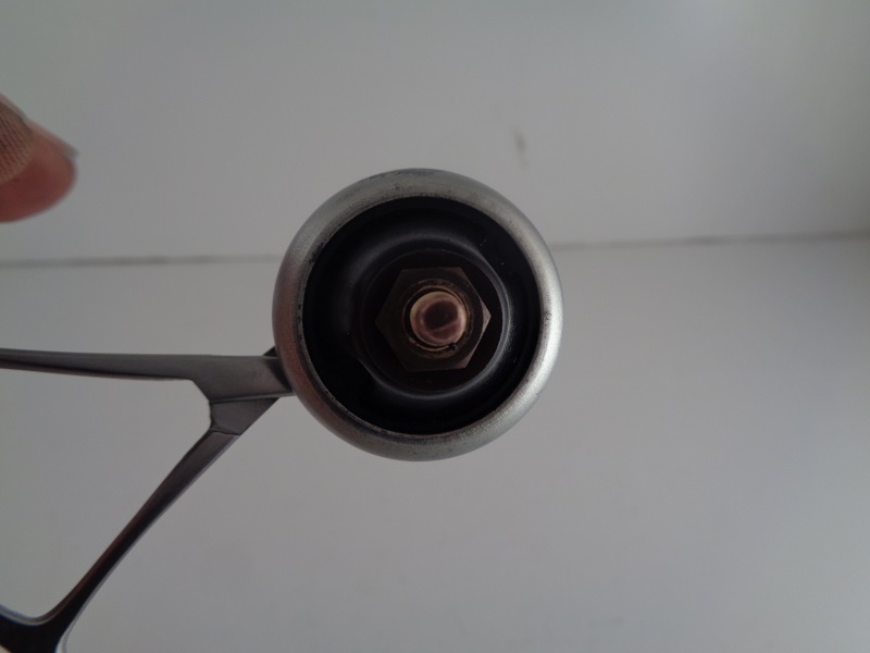
Oil Pump Check Valve
The oil pump check valve plays a role in the operation of the oil pressure switch.
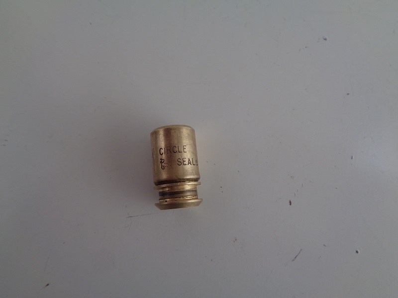

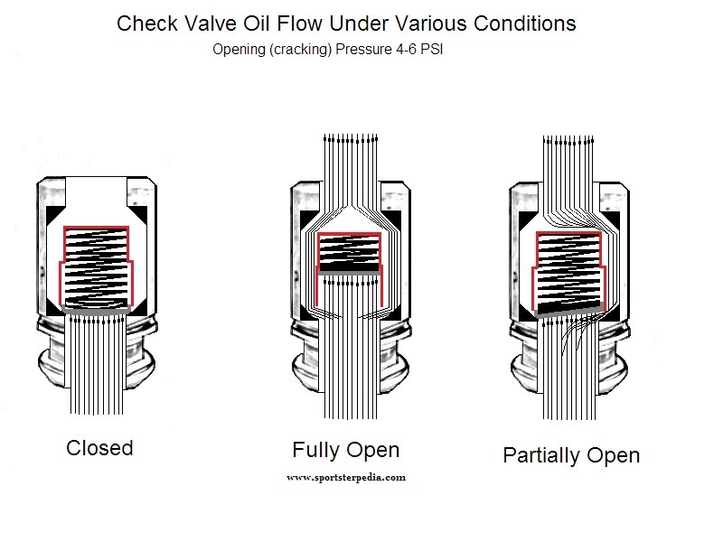
The check valve is not a pass through but instead a cartridge type one way check valve operated by a spring loaded cup against a seat pressing at 4-6 PSI.
Oil pressure enters the center of the check valve, lifts the cup against its spring and exits the check valve by pushing around and past the cup and into the engine.
At a point, the cup will float off it's seat up against the spring towards the end of it's travel.
According to the FSM, the check valve has two main functions;
It prevents gravity oil drainage from the tank to the engine when not in operation.
It also acts as a restriction to activate the oil pressure switch.
Without the check valve, the pressure would not build up as much in the 'pocket' in the pump (see drawing above).
It would free flow into the crankcase and disperse.
With the check valve installed and the oil having to find it's way around the cup, pressure builds behind it in the pocket.
This back pressure builds inside the pump and pushes the pressure switch contacts open, shutting off the oil light.
The check valve spring does not control the amount of oil that enters the engine (unless it's stuck closed).
The flow goes past the check no matter what. The spring pressure is very light.
It regulates (creates and manages) the oil pressure in the pocket next to the switch before it enters the engine.
That pocket is protected for one reason (to operate the oil switch, therefore the oil light).
If you are not running an oil light, there is no reason to be concerned with the check valve (in regards to a running engine).
You could remove the light and the check and it would not affect the oil flow thru the engine.
The positive displacement oil pump will still deliver oil.
The check/switch/light is a safety precaution to let you see the light and warn you that the pressure in the pocket is low.
In theory and design, if the pressure in the pocket is low, oil flow would also be low.
In practice, there are too many variables on a worn engine,pump, check, switch etc. to keep theory and design true all the time.
The cup will stay off it's seat and open as long as there is sufficient oil pressure pushing against its spring.
This spring actuates the 4-6 PSI pressure that the pump must overcome.
If there is not enough oil pressure coming from the pump to keep the check valve cup completely or partially off it's seat;
The back pressure from the spring will push the cup toward it's seat, or closed position, equal to the amount of minimum pressure loss from the pump.
Thinner (hotter) oil flows faster and builds less pressure.
When the oil thins out, the oil pressure will still try to push past the cup.
At a point, the pressure from the pump may not be sufficient to completely float the cup off it's seat.
So, the cup will turn sideways a bit only allowing oil to pass it on one side.
This reduction in pressure is also sensed by the oil pressure switch.
When the pressure drops, the diaphragm eases back toward the closed position.
If the pressure is low enough, the contacts will close or partially make contact while closing or intermittently opening and closing.
The oil light will come on or flicker depending on the action of the contacts.
The pressure switch requires no back pressure from the engine to stay open.
It opens solely from the pressure generated from the oil pump with the assistance of the check valve to hold some of that pressure in the pump.
So, it is possible but not likely to have a stuck closed check valve with no oil light on.
Top End Oiling
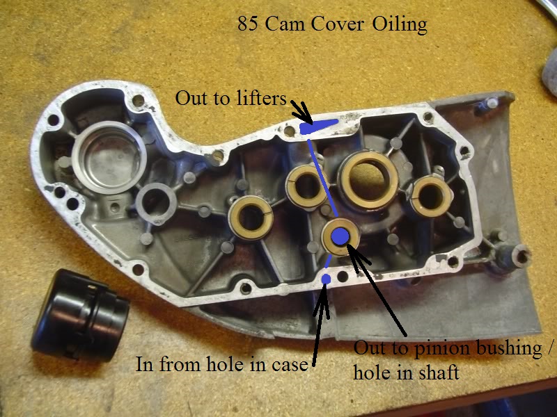
Cam Cover Oiling
The oil going up to the top end not only passes by the bushing in the cam chest, but also is fed to and from the cam cover and through the cam cover gasket. 61)
It is possible for the gasket to blow out and seal up the oil galley feed passages.
Also if silicon was used on the cover, it is possible for that to break loose and stop up the passages.
You can take the cover off and run a tap down all the threaded holes to clear out any obstructions.
Also check that the face of the cover and case are not marred by some big scratch or dent.
To get old silicone out of bolt holes, you can use an inflation needle for footballs/basketballs/soccerballs. 62)
Cut the tip off of it then screw it into the end of an air blowgun.
It's narrow enough that it doesn't block debris from getting out of the hole.
| Oil path of 85 style cam cover 63) |
 |
Oil Lines to the Rockers
There are rubber grommets on both ends of the oil lines. 64)
Some guys install two on each end, which is a wrong thing to do.
Sometimes the rubber from an improperly installed grommet plugs the oil line.
Before going into the gearcase (to check for low / no oil to the rocker boxes);
Remove both oil lines, and check the rubbers on both ends of each.
| Oil line sleeves. 65) | |
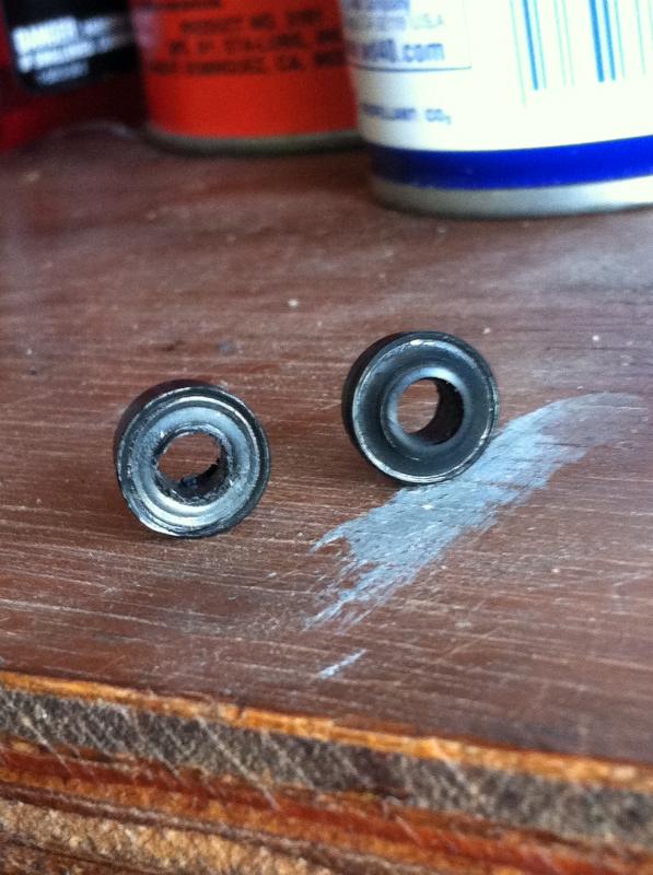 | 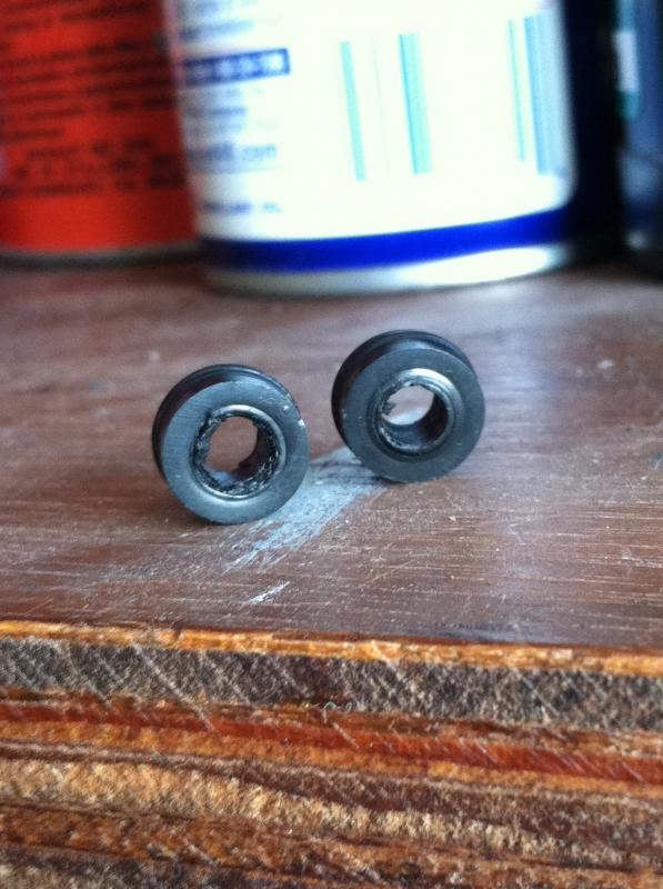 |
Rocker Box
The feed to the rockers is not a large diameter passage and not a lot of oil goes to the rocker gear. 66)
But if you pull the lines off with the engine running you should be getting a good steady flow out of them.
Bottom End Oiling
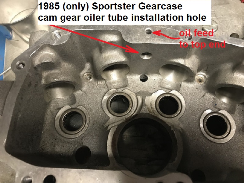
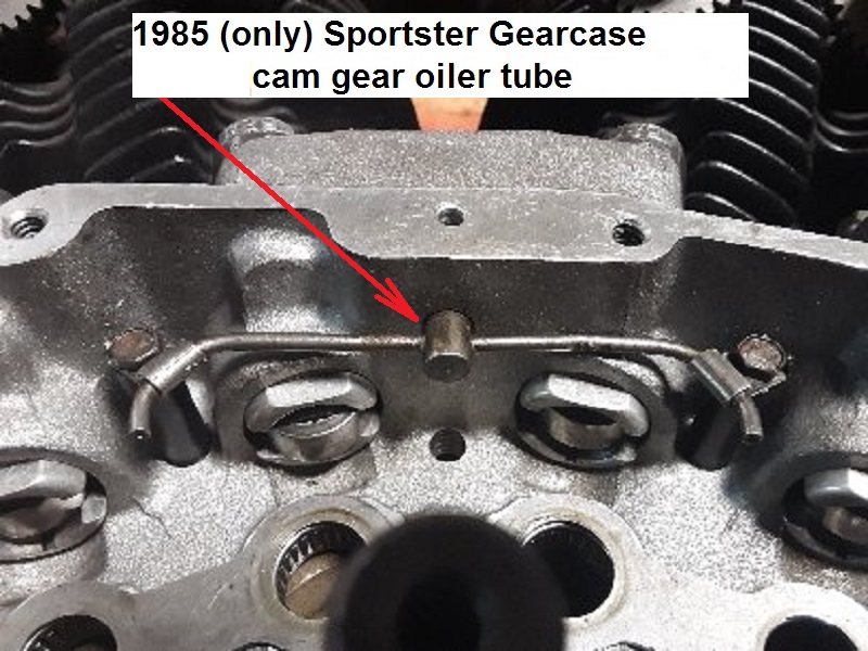
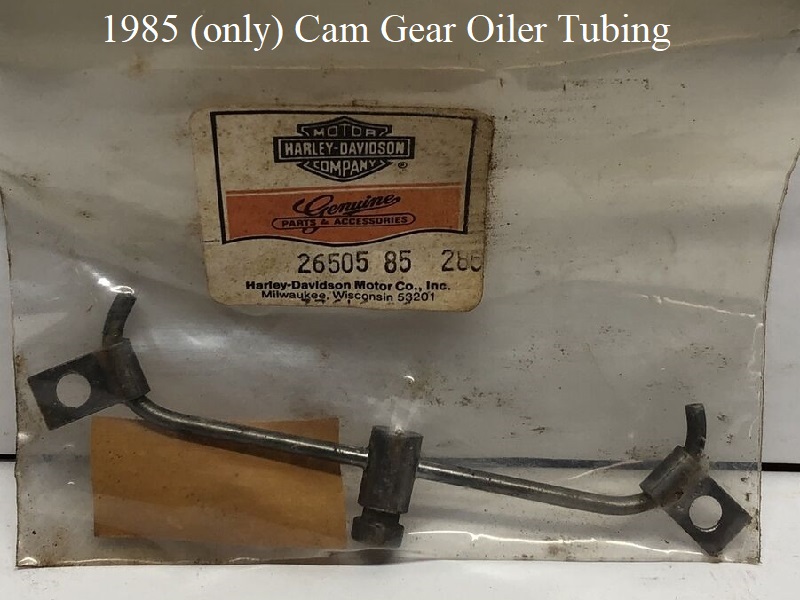
Cam Gear Oiler (1985 models only)
Starting with crankcase number 785 303 002, manufactured after October 29, 1984, a cam gear oiler was installed in the gearcase ceiling. 67)
Click Here to download Service Bulletin #M-899 for more details.
This is a one year only addition. In 1986, the MoCo deleted the tubing and installed a pressure bypass on the oil filter pad.
Then in 1992, they deleted the pressure bypass and simply drilled a .060” hole in the gearcase roof instead (similar to the 85 cam oiler system).
So the cam oiler tubing acts functions for cam lubrication as well as a high pressure release for the upper oil feed galley.
The cam gear oiler directs over-pressured oil from the upper feed galley to the gear mesh between the cams with 4 small holes in the tubing.
Direct lubrication of the gear teeth allows tighter gear fitment. Gear backlash and noise are reduced.
- The oiler tube has restricted orifices to spray the gears and still retain main oil feed pressure from whence the oil came (top oil feed galley).
- There is an O-ring on the oiler tube nipple that is pressed into the ceiling of the gearcase.
- If the O-ring fails to seal the oiler tube, feed oil pressure to the top end could be low.
Transfer Valve (76 and earlier)
Sub Documents
The transfer valve is not the crankcase vent (aka foo-foo valve). The crankcase vent fitting wasn't used until the 1977 model year.
It was installed in 77-78 engines only in the cam cover and vents crankcase pressure (air) to atmosphere.
Explanation for the foo-foo valve is here in the Sportsterpedia.
The transfer valve (25075-55) is installed in the left case between the primary and crankcase compartments. 71)
There is only one moving part in the transfer valve assembly which is the triangular shaped disc in the pics below.
It's a triangular piece of .009“ thick stainless steel that can move about .015” left to right in the valve. There is no spring.
In a running engine, it is a one way valve that lets air and oil pass through it from primary case to flywheel case.
The video below was made by XLForum member, Harton, and shows how the transfer valve will move oil out of the primary into the crankcase.
But this is not indicative to true vacuum inside as the oil it's removing adds to engine vacuum until after the oil is removed.
The source for transfer is not the valve but rather piston upstroke.
Positive crankcase pressure pushes the valve disc to the left and seals a small hole preventing flow into the primary.
Vacuum in the crankcase pulls the disc to the right up against a stop that has a larger hole.
The 3 cuts that make the disc a triangle shape allows air/oil to flow around it into the crankcase.
Without the engine running and with no spring to maintain a tight seal, oil can slowly leak through and let wet sumped oil pass into the primary.
On engine start up the excess oil in the primary should be transferred back into the engine.
The transfer valve is not the culprit in getting engine oil to the primary side. You have to remedy the problem at the oil pump. 72)
This valve largely seals by dynamic action (aka windage) from the down stoke of the pistons. The disk is only a marginal seal at static, and yes it will leak.
An engine will produce more HP if there is a slight vacuum in the crankcase as it does not have to over come pressure.
However, excess vacuum can cause problems in scavenging the oil from the crankcase.
This valve lets a controlled amount of air into the crankcase.
Crankcase vapor and oil is sent through the timed breather valve on downstroke along with any oil that has gotten over the disk level when parked.
The flow is not from the crankcase to the primary. There is no advantage to removing the transfer valve.
The transmission on the models that use it are designed for engine oil.
Blocking it and going with gear oil can cause problems down the road if your crankcase fills up with oil.
You can always tell when the crankcase has excess oil as the rear cylinder will usually smoke until the oil is scavenged out.
You can also notice a reluctance in the engine wanting to run up as it is churning all of that excess oil around draining off HP.
The excess oil in the primary will be scavenged back to the engine through this valve.
Note: on race engines, it is imperative to not allow oil to hit the crank and that is why windage trays and baffled oil pans are used.
Not only can it rob HP but it can also cause crank deflection and failure.
See Further Study of the Transfer Valve Operation and Affects of Plugging the Valve above.
The transfer valve is staked into position. 73)
Look very close around the edges and you'll see two spots that have been lightly punched.
The thread pattern is 3/4“-16. 76)
There is nothing to wear out. However anything that stops the movement of the reed (rust or dirt) means the valve won't work.
The one taken apart here was gummed up with old oil that had a tar like consistency.
Also, as a test, a container of 20w-50 oil at room temperature was allowed to gravity drain from the transfer valve.
It took 48 hours for 100 milliliters of oil to drip through the valve.
Here are a few drawings detailing the assembly:
Removing / Installing the Transfer Valve
The transfer valve is staked into place and it is steel into alloy which is always problematic. 80)
If you do remove/replace the valve, make sure it is staked back in place when you finish. Use some Loctite on the threads also.
- You can use a hammer and punch to stake mark out of the valve slot. Be careful when hammering on your cases. 81)
- You can find a socket that same size as the OD of the valve. 82) Lay it on the valve & give it some face hammer shots. Again, be careful.
Or get 2 hammers, 2 drifts, 2 guys, one for each slot. Get in rhythm so both hit at same time.
You don't want to brutal. It will break loose if you repeat 2&3. Be careful not to mash the valve into the case. That would re-stake the valve. Again, be careful.
| Special tool to remove / install transfer valve. 86) |